2012-2013 Dodge Grand Caravan Remote Start Pictorial
Printed From: the12volt.comForum Name: Car Security and Convenience - Alarm/Remote Start Pictorials
Forum Discription: Installer submitted Alarm, Keyless Entry, and Remote Start Pictorials from our Car Security and Convenience forum.
URL: https://www.the12volt.com/installbay/forum_posts.asp?tid=134484
Printed Date: April 19, 2026 at 1:33 PM
Topic: 2012-2013 Dodge Grand Caravan Remote Start Pictorial
Posted By: kreg357
Subject: 2012-2013 Dodge Grand Caravan Remote Start Pictorial
Date Posted: July 05, 2013 at 8:48 AM
This is a DIY Pictorial on a 2013 Dodge Grand Caravan. The 2012 and 2013 model years should be the same. This
includes the Chrysler Town & Country and the VW Routan. Additionally, the 2008 - 2011 model years will be similar
but there will be some minor wiring and wire appearance differences. The components used in this installation will
work in 2008 - 2013 models.
Installer notes :
As always, proper planning is important.
This vehicle was an SXT model and the only added option was the Factory Alarm. Being as the van already had an
alarm system, no aftermarket system was needed. The SXT includes power right & left sliding doors and power
rear hatch. All of these features can be incorporated into the Remote Start system with the Fortin EVO-ALL however
the Factory key FOB's include these buttons. More importantly the Factory FOB's continue to work during the
remote start period, so a remote start system with a small one-button remote is a good choice. The one button R/S
system is slightly less expensive and there is no sense in carrying around a large remote when the Factory Key Fob
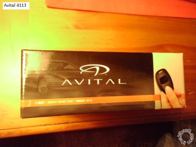
still works. The Avital 4113 Remote Start system was chosen due to it's price, general availability, reliability and
features. However, any quality remote starter system can be used.
Here is a link to the Avital 4113 Install Guide : https://www.the12volt.com/installbay/file.asp?ID=1212
Please note that while the van had the Factory Alarm, it does not have a hood pin nor monitor the hood. This is
important because while the Fortin bypass module indicates that it can supply a hood pin signal, this is only true
if the van has a Factory installed hood pin switch. Test the van first by setting the Factory Alarm system while sitting
in the van and then releasing the hood.
The Fortin bypass module was chosen for several reasons. The comparable bypasses ( DB-ALL and ADS AL CA )
both require a firmware load specific to the vehicle using a special USB flash cable ( and dealer access to the WEB
site in the case of the iDatalink ADS AL CA module ). The Fortin EVO-ALL should come loaded with the most current
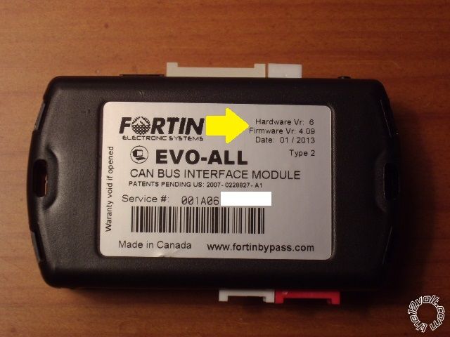
firmware making it very DIYer friendly. For this install, an EVO-ALL with a minimum of firmware V4.09 and Hardware
V 3 is required. This should not represent a problem if purchased from a reputable dealer. Just beware of "online
auctions" selling old, out of date modules. Below is a picture of the EVO-ALL with the H/W and S/W version location
on the manufacturers sticker marked. ( This indicates the S/W version that was loaded during manufacture and can
be changed by anyone with a Fortin FlashLink cable ($60 ) and a PC with internet access.)
For this install, the EVO-ALL was flashed with the latest firmware, V 74.02. Here is a link to the current EVO-ALL
install guide for a 2013 Dodge Grand Caravan : https://ifar.ca/download/9691/preview.html
System Prep :
Making all of the necessary wire connections between the Avital 4113 and the EVO-ALL on the bench, under ideal
conditions, will make for a reliable system and an easy install. Out of the box, the EVO-ALL is not D2D compatible
with the Avital remote start unit. Therefore, the interconnections were done with the W2W method. While it does
consume more time, the results will make it worthwhile. Using the W2W method will allow the EVO-ALL to work
with any brand / model of R/S system.
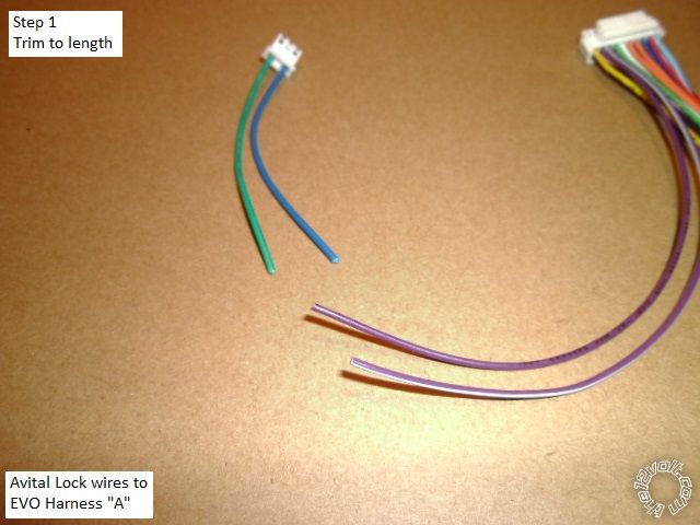
After looking over the install guides for the EVO-ALL and the Avital, the first time DIYer's will have a question. Here is
the answer, "Yes, there are a lot of wires and No, not all of them will be used." Here is a photo of the scrap left-overs
after bench prep.

There will be more wire left-over from the actual vehicle install as each wire is wire, located, secured, cut to length
and soldered. While it looks like a daunting task, remember, there will be only seven wire connections to the vehicle.
For this install, here is the wire connection list :
Avital 4113 Wire Function Destination
H1/1 LIGHT GREEN/ BLACK FACTORY ALARM DISARM Not Used
H1/2 GREEN / WHITE FACTORY REARM Not Used
H1/3 YELLOW (+) IGNITION OUT (TO ALARM)Not Used
H1/4 WHITE/ BLUE (-) ACTIVATION INPUT Not Used
H1/5 BROWN (-) HORN OUTPUT Not Used ** Chrysler vehicles do not respond well
H1/6 ORANGE (-) GROUND WHEN LOCKED* Not Used
H1/7 RED / WHITE (-) TRUNK RELEASE OUTPUT* Not Used
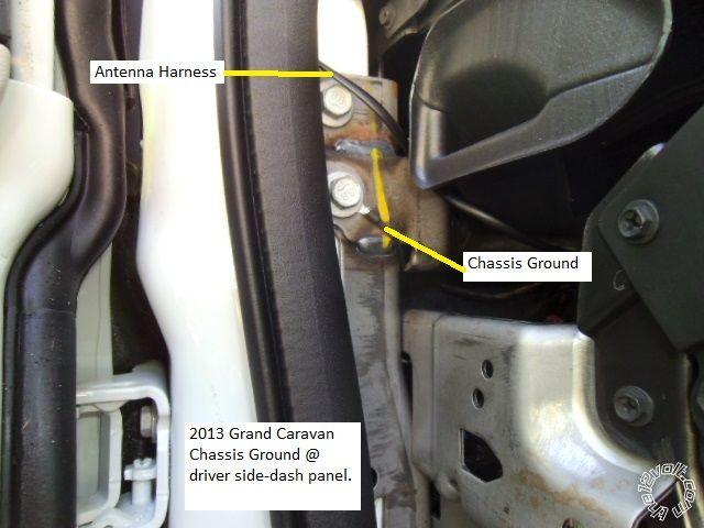
H1/8 BLACK GROUND Vehicle Chassis Ground
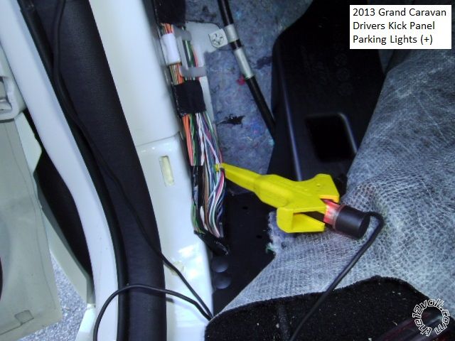
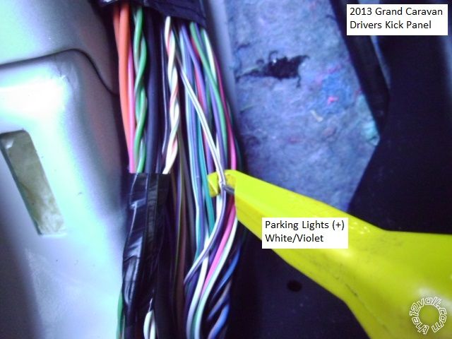
H1/9 WHITE (+/-) LIGHT FLASH Set to (+) Vehicle WHITE/ Violet in DKP
H2/1 BLACK/ WHITE (-) NEUTRAL SAFETY SWITCH INPUT To Chassis Ground thru valet switch
H2/2 VIOLET/WHITE TACHOMETER INPUT WIRE EVO-ALL Pink wire @ A12
H2/3 BROWN (+) BRAKE SWITCH SHUTDOWN WIRE EVO-ALL Black wire @ A11
H2/4 GRAY (-)HOOD PINSWITCH SHUTDOWN WIRE Hood Pin switch from kit ( or better alternative )
H2/5 BLUE/WHITE (-) 200mA 2ND STATUS/REAR DEFOG OUTPUTEVO-ALL Dark Blue wire @ A8
4-pin satellite harness diagram
1 BLUE STATUS OUTPUT Not Used ( Used 2nd Status instead )
2 ORANGE (-) ACCESSORY OUTPUT Not Used
3 PURPLE (-) STARTER OUTPUT Not Used
4 PINK (-) IGNITION OUTPUT Not Used ****
**** Warning : This wire is mis-labeled as (-) Starter in the install guide on Page 12.
Heavy gauge wires
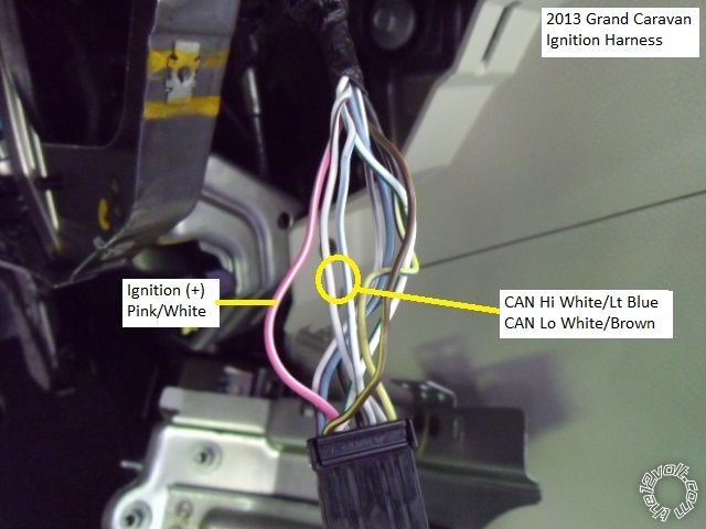
1 PINK (+) (30 AMP) OUTPUT TO IGNITION CIRCUIT Vehicle Pink/White @ ignition harness **
2 PURPLE (+) (30 AMP) OUTPUT TO STARTER CIRCUIT EVO-ALL RED / Blue wire @ A9
3 ORANGE (+) (30 AMP) OUTPUT TO ACCESSORY CIRCUIT Not Used
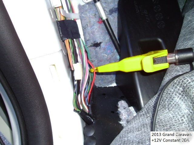
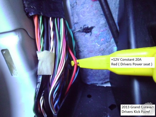
4 RED (+) (30A) HIGH CURRENT 12 INPUT Vehicle Red +12V Constant in DKP ***
5 PINK/WHITE (+) PROGRAMMABLE OUTPUT FOR ACC OR IGN Not Used
6 RED (+) (30A) HIGH CURRENT 12V INPUT Vehicle Red +12V Constant in DKP ***
*** The two Red wires can be joined together and fused down to 10A. The Red +12V source wire in the DKP is for the
driver's power seat. This vehicle did not have the driver power seat option.
** Please note that the EVO-All install guide incorrectly lists the vehicle Ignition wire as RED / White.
Door lock harness, 3-pin connector
1 GREEN (-) LOCK OUTPUT * Not Used
2 EMPTYNOT USED
3 BLUE (-) UNLOCK OUTPUT EVO-ALL PURPLE / White wire @ A3
Please note that the Avital one button remote can perform an Unlock during remote start run time and can be
useful if the factory key FOB is lost, locked inside the vehicle or the FOBs' battery dies.
Here is the wire connections from the EVO-ALL side of things, some of which have been mentioned already.
Wires not listed are not necessary for this install.
EVO-ALL Description Destination
A1 Yellow Ignition Viper Pink heavy gauge Ignition Output
A3 PURPLE / White Unlock Viper Blue unlock output
A8 Dark Blue GWR Viper Blue/White 2nd Status Output
A9 RED / Blue Starter Viper Purple heavy gauge Starter Output
A11 BlackBrake Pedal Viper Brown Brake Switch Shutdown wire
A12 Pink Tach Viper Violet /White Tach Input wire
C3 Gray CAN Hi Vehicle WHITE/ Light Blue @ Ignition switch harness
C4 Gray/Black Can Lo Vehicle WHITE/ Brown @ Ignition switch harness
The EVO-ALL install guide #5131 incorrectly lists the CAN Hi and CAN Lo wire colors. The above listed colors are
correct. These wires will be in a twisted-pair arrangement.
D2 Yellow/Blue +12V Viper Red heavy gauge +12V power fused input
D3 Yellow/Red Ignition Viper Pink heavy gauge Ignition Output
4 Pin Datalink Harness - cut harness
Red wire +12V Viper Red heavy gauge +12V power fused input
Black wire Chassis Ground Viper H1/8 Black Chassis Ground
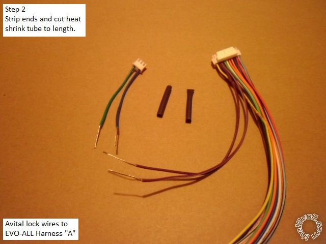
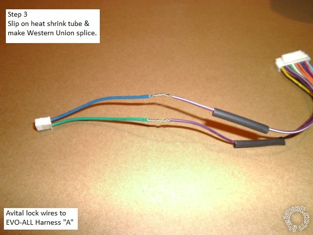
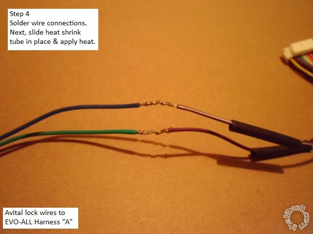
The connections made during bench prep should be neatly trimmed to length, soldered and insulated with heat
shrink tube. Below are photos of some wires connections being made using the Western Union type splice with
solder and heat shrink tube.
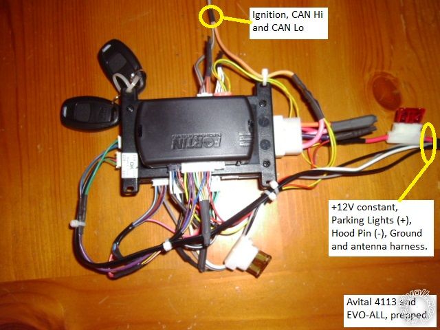
Here is a photo of the completed assy. As mentioned, there are only 7 connections to the vehicle. Three wires
at the ignition switch harness, three wires in the DKP and one wire to the engine compartment for the Hood Pin.
Notice that the wires have been split into the groups that will be routed to the proper vehicle destination. The
Avital antenna harness is included with the DKP group and will continue up to the windshield.
Leave enough slack in the harnesses to allow for the EVO-ALL programming procedure and trouble shooting. The
main power 10 Amp fuse will be removed during installation and not re-install until all the wires have been connected.
Unused wires can be cut, grouped together and insulated / secured with a piece of heat shrink tube.
Disassembly :
Using a non-marring trim tool, remove the dash side-panel as shown in the picture below.
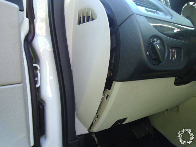
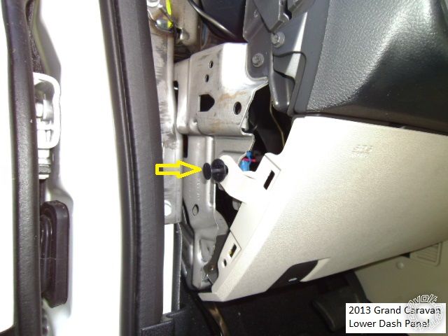
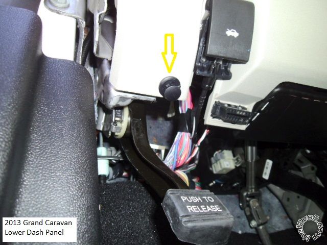
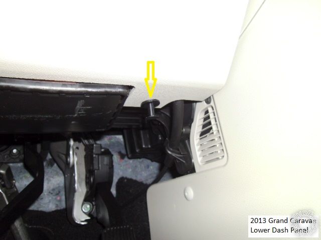
There are three retaining fasteners holding the side and bottom of the lower dash panel. Using a screwdriver, gently
pull the center section out, then remove the remaining outer piece. The pictures below show the popper locations.
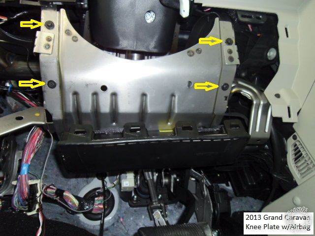
Remove the knee plate / air bag assy by removing the four 7mm machine screws shown. Do not unplug the
airbags' yellow harness, just rotate the assy and rest it against the center console.
To remove the Driver Kick Panel, lift the drivers door sill at the front edge and pull the DKP straight back.
Vehicle Wiring :
Here is a photo of the Ignition Harness connector, removed from the ignition switch.
These photo's are of the Parking Light wire in the DKP.
This is a shot of a convenient +12V constant source in the DKP.
This is a picture of a convenient, solid chassis ground point in the driver side-dash area.
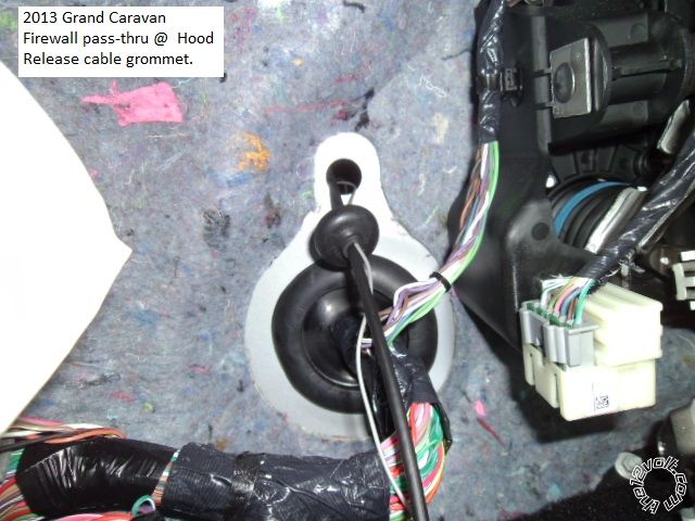
Here is photo of a firewall pas-thru for the Hood Pin wire.
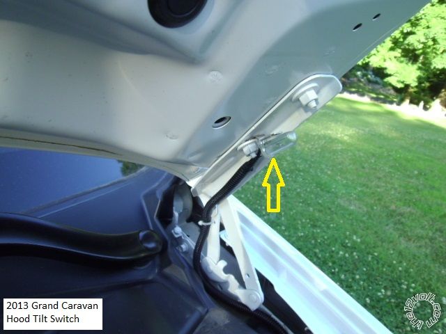
The Hood Pin switch is an important safety feature. All R/S kits include a hood pin, however, depending on the
mounting location, they are prone to rust and fail with in a year or two. Pictured below is a more reliable mercury
tilt switch.
Depending on the R/S assy install location, some wires might need to be extended. In this install, the Parking
Light wire and the main +12V power wire were extended to allow for neat routing to the lower driver kick panel
area.
After all wires are properly connected, verify that all EVO-ALL connectors are unplugged, then insert the main
power fuse(s). Follow the EVO-ALL programming procedure. Next change the Avitals' programming to Tach
Mode and preform the Tach Learn process. The rest of the Avitals' programming options will work OK in their
default setting.
At this point the R/S should be fully functional but there are several tests necessary to verify safety and functionality.
1. Remote start the van, wait a 20 seconds and apply the Brake. The engine should shutdown.
2. Remote start the engine and raise the hood. The engine should shutdown.
3. Verify that it is impossible to remove the key from the ignition cylinder unless the transmission shifter is in Park.
4. Verify that the Avital FOB can unlock the doors while the engine is running under remote start.
5. Try a key take-over and then a PitStop.
6. Check for proper antenna placement by attempting R/S's from various angles and distances.
The final steps are securing the R/S assy and making sure all wires are safely and neatly routed away from heat,
chaffing and allow for the Tilt / Telescopic steering wheel adjustments. Replace all removed trim panels to complete
the install.
Additional thoughts :
If adding a remote start with alarm system and keyless entry, the EVO-ALL will supply the door and rear hatch
status signals and allow the R/S system to control the locks, sliding door and hatch ( when wired correctly )
A van with the Factory Alarm will require a R/S system that can be programmed to Unlock the doors, remote start
the engine and then re-lock the doors. This will disarm the alarm and prevent the horn from beeping. Another
way to achieve this is with an EVO-ALL programming option using the Fortin FlashLink programming cable. There
are other methods but that would go beyond the scope of this DIY pictorial.
With the Fortin FlashLink programming cable the EVO-ALL can be set-up as a stand alone R/S unit. This will eliminate
the need for the Avital 4113 but does require the FlashLink cable. The downside you will be using the Factory FOB
and three Lock commands to remote start the engine. This limits the range and causes the horn to beep with each
lock command. Addition parts will be required for this type install ( relay for the Parking Lights and a Hood Pin switch ).
Total cost of this install = $110 ( using the R/S kit hood pin ). Total time for the average DIYer will be about 4 hours,
which includes bench prep, install, programming, testing and clean-up. This install can be done in slightly less time
with the Fortin THAR-CHR4 T-Harness for about $25 more.
Required tools are :
Digital Multi Meter
Socket wrench with 13mm and 7mm sockets
Flat blade screwdriver
Drop light / flashlight
Soldering gun
Solder
Scotch Super 33+ tape
Heat Shrink tube
Diagonal cutters
Wire strippers
Exacto knife
Butane lighter
Tie wraps
Trim tools ( or strong finger nails )
ATC fuses, 5 & 10 amp
Split tube wire loom
-------------
Soldering is fun!
includes the Chrysler Town & Country and the VW Routan. Additionally, the 2008 - 2011 model years will be similar
but there will be some minor wiring and wire appearance differences. The components used in this installation will
work in 2008 - 2013 models.
Installer notes :
As always, proper planning is important.
This vehicle was an SXT model and the only added option was the Factory Alarm. Being as the van already had an
alarm system, no aftermarket system was needed. The SXT includes power right & left sliding doors and power
rear hatch. All of these features can be incorporated into the Remote Start system with the Fortin EVO-ALL however
the Factory key FOB's include these buttons. More importantly the Factory FOB's continue to work during the
remote start period, so a remote start system with a small one-button remote is a good choice. The one button R/S
system is slightly less expensive and there is no sense in carrying around a large remote when the Factory Key Fob
still works. The Avital 4113 Remote Start system was chosen due to it's price, general availability, reliability and
features. However, any quality remote starter system can be used.
Here is a link to the Avital 4113 Install Guide : https://www.the12volt.com/installbay/file.asp?ID=1212
Please note that while the van had the Factory Alarm, it does not have a hood pin nor monitor the hood. This is
important because while the Fortin bypass module indicates that it can supply a hood pin signal, this is only true
if the van has a Factory installed hood pin switch. Test the van first by setting the Factory Alarm system while sitting
in the van and then releasing the hood.
The Fortin bypass module was chosen for several reasons. The comparable bypasses ( DB-ALL and ADS AL CA )
both require a firmware load specific to the vehicle using a special USB flash cable ( and dealer access to the WEB
site in the case of the iDatalink ADS AL CA module ). The Fortin EVO-ALL should come loaded with the most current
firmware making it very DIYer friendly. For this install, an EVO-ALL with a minimum of firmware V4.09 and Hardware
V 3 is required. This should not represent a problem if purchased from a reputable dealer. Just beware of "online
auctions" selling old, out of date modules. Below is a picture of the EVO-ALL with the H/W and S/W version location
on the manufacturers sticker marked. ( This indicates the S/W version that was loaded during manufacture and can
be changed by anyone with a Fortin FlashLink cable ($60 ) and a PC with internet access.)
For this install, the EVO-ALL was flashed with the latest firmware, V 74.02. Here is a link to the current EVO-ALL
install guide for a 2013 Dodge Grand Caravan : https://ifar.ca/download/9691/preview.html
System Prep :
Making all of the necessary wire connections between the Avital 4113 and the EVO-ALL on the bench, under ideal
conditions, will make for a reliable system and an easy install. Out of the box, the EVO-ALL is not D2D compatible
with the Avital remote start unit. Therefore, the interconnections were done with the W2W method. While it does
consume more time, the results will make it worthwhile. Using the W2W method will allow the EVO-ALL to work
with any brand / model of R/S system.
After looking over the install guides for the EVO-ALL and the Avital, the first time DIYer's will have a question. Here is
the answer, "Yes, there are a lot of wires and No, not all of them will be used." Here is a photo of the scrap left-overs
after bench prep.
There will be more wire left-over from the actual vehicle install as each wire is wire, located, secured, cut to length
and soldered. While it looks like a daunting task, remember, there will be only seven wire connections to the vehicle.
For this install, here is the wire connection list :
Avital 4113 Wire Function Destination
H1/1 LIGHT GREEN/ BLACK FACTORY ALARM DISARM Not Used
H1/2 GREEN / WHITE FACTORY REARM Not Used
H1/3 YELLOW (+) IGNITION OUT (TO ALARM)Not Used
H1/4 WHITE/ BLUE (-) ACTIVATION INPUT Not Used
H1/5 BROWN (-) HORN OUTPUT Not Used ** Chrysler vehicles do not respond well
H1/6 ORANGE (-) GROUND WHEN LOCKED* Not Used
H1/7 RED / WHITE (-) TRUNK RELEASE OUTPUT* Not Used
H1/8 BLACK GROUND Vehicle Chassis Ground
H1/9 WHITE (+/-) LIGHT FLASH Set to (+) Vehicle WHITE/ Violet in DKP
H2/1 BLACK/ WHITE (-) NEUTRAL SAFETY SWITCH INPUT To Chassis Ground thru valet switch
H2/2 VIOLET/WHITE TACHOMETER INPUT WIRE EVO-ALL Pink wire @ A12
H2/3 BROWN (+) BRAKE SWITCH SHUTDOWN WIRE EVO-ALL Black wire @ A11
H2/4 GRAY (-)HOOD PINSWITCH SHUTDOWN WIRE Hood Pin switch from kit ( or better alternative )
H2/5 BLUE/WHITE (-) 200mA 2ND STATUS/REAR DEFOG OUTPUTEVO-ALL Dark Blue wire @ A8
4-pin satellite harness diagram
1 BLUE STATUS OUTPUT Not Used ( Used 2nd Status instead )
2 ORANGE (-) ACCESSORY OUTPUT Not Used
3 PURPLE (-) STARTER OUTPUT Not Used
4 PINK (-) IGNITION OUTPUT Not Used ****
**** Warning : This wire is mis-labeled as (-) Starter in the install guide on Page 12.
Heavy gauge wires
1 PINK (+) (30 AMP) OUTPUT TO IGNITION CIRCUIT Vehicle Pink/White @ ignition harness **
2 PURPLE (+) (30 AMP) OUTPUT TO STARTER CIRCUIT EVO-ALL RED / Blue wire @ A9
3 ORANGE (+) (30 AMP) OUTPUT TO ACCESSORY CIRCUIT Not Used
4 RED (+) (30A) HIGH CURRENT 12 INPUT Vehicle Red +12V Constant in DKP ***
5 PINK/WHITE (+) PROGRAMMABLE OUTPUT FOR ACC OR IGN Not Used
6 RED (+) (30A) HIGH CURRENT 12V INPUT Vehicle Red +12V Constant in DKP ***
*** The two Red wires can be joined together and fused down to 10A. The Red +12V source wire in the DKP is for the
driver's power seat. This vehicle did not have the driver power seat option.
** Please note that the EVO-All install guide incorrectly lists the vehicle Ignition wire as RED / White.
Door lock harness, 3-pin connector
1 GREEN (-) LOCK OUTPUT * Not Used
2 EMPTYNOT USED
3 BLUE (-) UNLOCK OUTPUT EVO-ALL PURPLE / White wire @ A3
Please note that the Avital one button remote can perform an Unlock during remote start run time and can be
useful if the factory key FOB is lost, locked inside the vehicle or the FOBs' battery dies.
Here is the wire connections from the EVO-ALL side of things, some of which have been mentioned already.
Wires not listed are not necessary for this install.
EVO-ALL Description Destination
A1 Yellow Ignition Viper Pink heavy gauge Ignition Output
A3 PURPLE / White Unlock Viper Blue unlock output
A8 Dark Blue GWR Viper Blue/White 2nd Status Output
A9 RED / Blue Starter Viper Purple heavy gauge Starter Output
A11 BlackBrake Pedal Viper Brown Brake Switch Shutdown wire
A12 Pink Tach Viper Violet /White Tach Input wire
C3 Gray CAN Hi Vehicle WHITE/ Light Blue @ Ignition switch harness
C4 Gray/Black Can Lo Vehicle WHITE/ Brown @ Ignition switch harness
The EVO-ALL install guide #5131 incorrectly lists the CAN Hi and CAN Lo wire colors. The above listed colors are
correct. These wires will be in a twisted-pair arrangement.
D2 Yellow/Blue +12V Viper Red heavy gauge +12V power fused input
D3 Yellow/Red Ignition Viper Pink heavy gauge Ignition Output
4 Pin Datalink Harness - cut harness
Red wire +12V Viper Red heavy gauge +12V power fused input
Black wire Chassis Ground Viper H1/8 Black Chassis Ground
The connections made during bench prep should be neatly trimmed to length, soldered and insulated with heat
shrink tube. Below are photos of some wires connections being made using the Western Union type splice with
solder and heat shrink tube.
Here is a photo of the completed assy. As mentioned, there are only 7 connections to the vehicle. Three wires
at the ignition switch harness, three wires in the DKP and one wire to the engine compartment for the Hood Pin.
Notice that the wires have been split into the groups that will be routed to the proper vehicle destination. The
Avital antenna harness is included with the DKP group and will continue up to the windshield.
Leave enough slack in the harnesses to allow for the EVO-ALL programming procedure and trouble shooting. The
main power 10 Amp fuse will be removed during installation and not re-install until all the wires have been connected.
Unused wires can be cut, grouped together and insulated / secured with a piece of heat shrink tube.
Disassembly :
Using a non-marring trim tool, remove the dash side-panel as shown in the picture below.
There are three retaining fasteners holding the side and bottom of the lower dash panel. Using a screwdriver, gently
pull the center section out, then remove the remaining outer piece. The pictures below show the popper locations.
Remove the knee plate / air bag assy by removing the four 7mm machine screws shown. Do not unplug the
airbags' yellow harness, just rotate the assy and rest it against the center console.
To remove the Driver Kick Panel, lift the drivers door sill at the front edge and pull the DKP straight back.
Vehicle Wiring :
Here is a photo of the Ignition Harness connector, removed from the ignition switch.
These photo's are of the Parking Light wire in the DKP.
This is a shot of a convenient +12V constant source in the DKP.
This is a picture of a convenient, solid chassis ground point in the driver side-dash area.
Here is photo of a firewall pas-thru for the Hood Pin wire.
The Hood Pin switch is an important safety feature. All R/S kits include a hood pin, however, depending on the
mounting location, they are prone to rust and fail with in a year or two. Pictured below is a more reliable mercury
tilt switch.
Depending on the R/S assy install location, some wires might need to be extended. In this install, the Parking
Light wire and the main +12V power wire were extended to allow for neat routing to the lower driver kick panel
area.
After all wires are properly connected, verify that all EVO-ALL connectors are unplugged, then insert the main
power fuse(s). Follow the EVO-ALL programming procedure. Next change the Avitals' programming to Tach
Mode and preform the Tach Learn process. The rest of the Avitals' programming options will work OK in their
default setting.
At this point the R/S should be fully functional but there are several tests necessary to verify safety and functionality.
1. Remote start the van, wait a 20 seconds and apply the Brake. The engine should shutdown.
2. Remote start the engine and raise the hood. The engine should shutdown.
3. Verify that it is impossible to remove the key from the ignition cylinder unless the transmission shifter is in Park.
4. Verify that the Avital FOB can unlock the doors while the engine is running under remote start.
5. Try a key take-over and then a PitStop.
6. Check for proper antenna placement by attempting R/S's from various angles and distances.
The final steps are securing the R/S assy and making sure all wires are safely and neatly routed away from heat,
chaffing and allow for the Tilt / Telescopic steering wheel adjustments. Replace all removed trim panels to complete
the install.
Additional thoughts :
If adding a remote start with alarm system and keyless entry, the EVO-ALL will supply the door and rear hatch
status signals and allow the R/S system to control the locks, sliding door and hatch ( when wired correctly )
A van with the Factory Alarm will require a R/S system that can be programmed to Unlock the doors, remote start
the engine and then re-lock the doors. This will disarm the alarm and prevent the horn from beeping. Another
way to achieve this is with an EVO-ALL programming option using the Fortin FlashLink programming cable. There
are other methods but that would go beyond the scope of this DIY pictorial.
With the Fortin FlashLink programming cable the EVO-ALL can be set-up as a stand alone R/S unit. This will eliminate
the need for the Avital 4113 but does require the FlashLink cable. The downside you will be using the Factory FOB
and three Lock commands to remote start the engine. This limits the range and causes the horn to beep with each
lock command. Addition parts will be required for this type install ( relay for the Parking Lights and a Hood Pin switch ).
Total cost of this install = $110 ( using the R/S kit hood pin ). Total time for the average DIYer will be about 4 hours,
which includes bench prep, install, programming, testing and clean-up. This install can be done in slightly less time
with the Fortin THAR-CHR4 T-Harness for about $25 more.
Required tools are :
Digital Multi Meter
Socket wrench with 13mm and 7mm sockets
Flat blade screwdriver
Drop light / flashlight
Soldering gun
Solder
Scotch Super 33+ tape
Heat Shrink tube
Diagonal cutters
Wire strippers
Exacto knife
Butane lighter
Tie wraps
Trim tools ( or strong finger nails )
ATC fuses, 5 & 10 amp
Split tube wire loom
-------------
Soldering is fun!
Replies:
Posted By: smokeman1
Date Posted: July 06, 2013 at 6:15 AM
Fantastic!!! Excellent writeup, & photos. You should have Ph.D after you name.
-------------
When all else fails, Read the Instructions
Support the12volt.com Make a Donation
-------------
When all else fails, Read the Instructions
Support the12volt.com Make a Donation
Posted By: kreg357
Date Posted: July 06, 2013 at 1:52 PM
Ah, shucks.  Thanks for the kind words, Mr. Smoke. Think we both enjoy sharing information and helping out.
Here is some more information on the "tilt switch". They are best when used for a non-alarm installations due to the
distance the hood has to be raised before it triggers. They are sold by several manufacturers under various designations.
Directed = 8613 and 8623
Omega = AU-46
Mobilistics Negative triggered Mercury Switch
Code Alarm Roller Ball Contact Tilt Switch TL200
When mounted to the hood support hinge bolt, it is quick with no holes to drill or future rust to worry about.
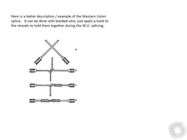
Below is a diagram of the Western Union wire splice method. It is good for butt splices and provides excellent strength
& connection reliability.
-------------
Soldering is fun!
Thanks for the kind words, Mr. Smoke. Think we both enjoy sharing information and helping out.
Here is some more information on the "tilt switch". They are best when used for a non-alarm installations due to the
distance the hood has to be raised before it triggers. They are sold by several manufacturers under various designations.
Directed = 8613 and 8623
Omega = AU-46
Mobilistics Negative triggered Mercury Switch
Code Alarm Roller Ball Contact Tilt Switch TL200
When mounted to the hood support hinge bolt, it is quick with no holes to drill or future rust to worry about.
Below is a diagram of the Western Union wire splice method. It is good for butt splices and provides excellent strength
& connection reliability.
-------------
Soldering is fun!
Posted By: smokeman1
Date Posted: July 06, 2013 at 2:43 PM
You are most welcome. Always good and informative to read your posts.
I use the tilt switch for hood pins on all of my installs. More reliable than the push pin type. The winter corrosion here in Wisconsin eats those cheap hood pins up and then its remote start with hood open. Not a good thing.
-------------
When all else fails, Read the Instructions
Support the12volt.com Make a Donation
Posted By: lucasoil4u
Date Posted: July 17, 2013 at 2:50 PM
Very nice install!