2005-2007 Mercury Mariner Remote Start Pictorial
Printed From: the12volt.comForum Name: Car Security and Convenience - Alarm/Remote Start Pictorials
Forum Discription: Installer submitted Alarm, Keyless Entry, and Remote Start Pictorials from our Car Security and Convenience forum.
URL: https://www.the12volt.com/installbay/forum_posts.asp?tid=135376
Printed Date: April 19, 2026 at 2:38 AM
Topic: 2005-2007 Mercury Mariner Remote Start Pictorial
Posted By: kreg357
Subject: 2005-2007 Mercury Mariner Remote Start Pictorial
Date Posted: November 25, 2013 at 9:43 PM
This is a DIY Pictorial for the installation of a remote start w/keyless entry system into a 2005 Mercury Mariner.
The sister vehicles, 2005 - 2007 Ford Escape and Mazda Tribute, will be similar. This vehicle had the 3.0 V-6 engine
Factory Remote Keyless Entry, PATS3 engine immobilizer system and the Factory Alarm.
For this install a Compustar CS600-s system was chosen, however any quality remote start system can be used.
A bypass module is needed for the PATS3 and there are no "full feature" modules available. There are many good
quality bypass modules available for this vehicle but be aware that all of the common DIY friendly bypass modules
require two, unique, non-clone ignition keys for programming. Here is a partial list of DIY friendly bypass modules :
Directed PKFM PKALL 1100F
Fortin Key-OverRide-ALL EVO-Ride ( 40 Bit )
iDatalink ADS TBSL KO ADS TBSL TI
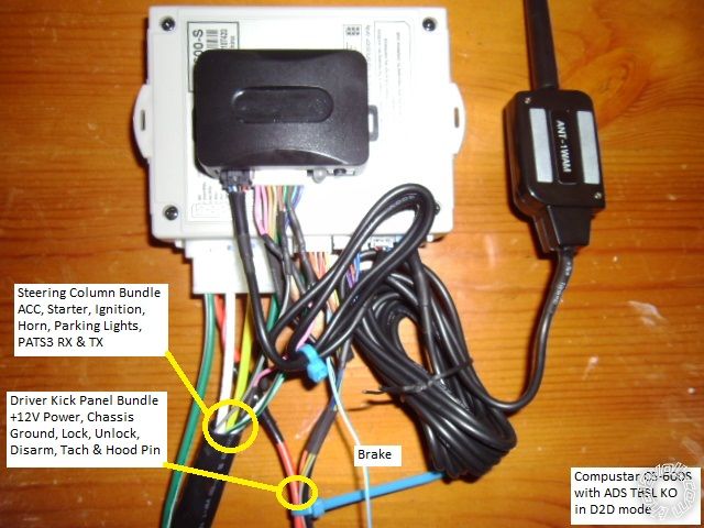
For this install, an ADS TBSL KO was chosen for it's reliability, ease of programming and D2D compatibility with
the Compustar CS600-s R/S unit. Below is a photo of the preliminary bench prep of the two modules. All unused
wires were cut to ~1.5 inches and bundled together and insulated with heat shrink tube.
This vehicle does not have "one-touch" starting so running in Tach Mode is deemed best for reliable year round
starting. This vehicle does not have built-in Anti-Grind so adding this feature should be considered.
Here is a list of the wire connections made during this install :
Compustar CS600-s 2005 Mercury Mariner
8 Pin heavy gauge connector
1. Red +12V BLACK/ Green in DKP *Note 1
2. GREEN / WHITE Parking Lights (+) not used
3. RED / White +12V Combined with Pin 1 Red, single wire, fused down to 20 Amps
4. White Accessory (+) BLACK/ Light Green @ Main Ignition Plug
5. Blue Flex Relay not used
6. Yellow Starter (+) Tan/Light Blue @ Main Ignition Plug
7. Green Ignition (+) Light GREEN/ Purple @ Main Ignition Plug
8. Black Chassis Ground Chassis Ground bolt in DKP
12 Pin Connector
1. GREEN / WHITE Parking Lights (-) WHITE/ Black in steering column @ Headlight connector
2. RED / Black (-) Starter Output not used
3. WHITE/ Black (-) Accessory Output not used
4. Black (-) Status GWR not used ( can be used for Anti-Grind w/ extra relay )
5. Orange (-)Rearm Output not used
6. ORANGE / White (-)Disarm Output Blue/Light Green @ DKP / door harness * Note 2 & 4
7. White (-) Horn Output Yellow/Light Green in steering column @ slip ring connector
8. Gray/Black (-) Hood Pin to installed, kit supplied, hood pin * Note 3
9. Light Blue/White (+) Foot Brake Light Green @ lower 2 Pin plug @ brake pedal
10. RED / White (-) Trigger Start not used
11. Red (+) Trigger Start not used
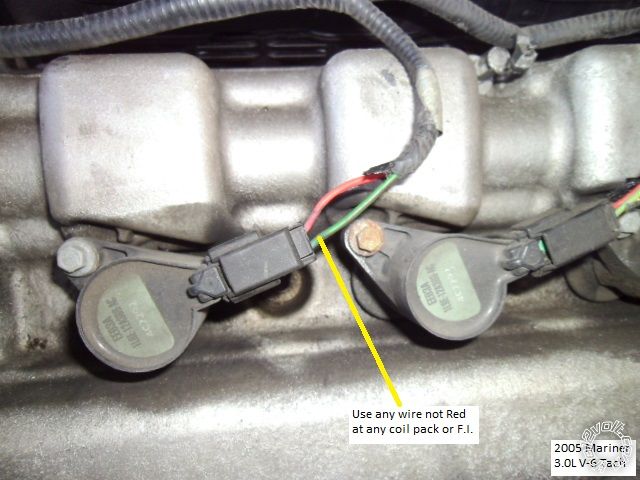
12. Yellow/Black Tach (AC) WHITE/ Pink @ PCM, in passenger side connector or any Coil Pack or F.I. - not Red
6 Pin Door harness
1. N/A
2. Violet/White (-) Trunk Release not used
3. ORANGE / Black (-) 2nd Unlock not used
4. Blue (-) Unlock Pink/White @ DPK / door harness * Note 2
5. Blue/Black (-) Lock WHITE/ Purple @ DPK / door harness * Note 2 & 4
6. N/A
Note 1 While the wire guides list the Red wire in the main ignition connector as +12V constant, it is fused at a mere
10 Amps. This is pretty marginal for the added R/S and bypass module, especially if using the (+) Parking Light wire
or with an alarm system. The +12V input wires for the R/S system were combined into one wire with a single 20 Amp
fuse and connected to the BLACK/ Green 12 gauge wire shown in the photo's. Running directly to the vehicles battery
is another option.
Note 2 This vehicle has a one-wire door lock system. Typical installs would use a Direct 451M door lock module
and a 1,000 ohm resistor. However, on vehicles with the Factory Alarm system it is preferable to use the Pink/White
one-wire door lock wire for Unlock, the WHITE/ Purple Factory Alarm Arm wire for Lock/Arm and the Blue/Light Green
Factory Disarm wire to disarm the system ( prior to an unlock and remote start ).
Note 3 This vehicle uses Ford's N.C. door trigger system. While this vehicle has a Factory Hood pin, the CS-600s
can only accept the more common N.O. Hood Pin input and the kit supplied hood pin should be installed and used.
( I used a mercury tilt switch, instead.)
Note 4 These wires are the key cylinder Arm & Disarm wires. Test for these wires while turning the key in the driver
door lock cylinder.
ADS TBSL KO wire connections :
4 Pin D2D to CS-600s 4 Pin D2D
9 Pin Plug
1. Pink Ignition Input to CS600-s thick Green (+)Ignition Output wire in 8 Pin Plug
2. Pink/Black not used
3. Orange not used
4. Gray/ Yellow not used
5. Gray/Red to Mariner Transponder Plug, Pin 3, BROWN / Orange
6. GREEN/ YELLOW not used
7. GREEN/ Red to Mariner Transponder Plug, Pin 4, RED / Black
8. Blue / YELLOW not used
9. Blue/Red not used
All of the necessary wires can be found in the steering column, the Driver Kick Panel, at the Brake pedal and under the
hood. Disassembly is straight forward. The center lower dash panel has 4 snap fasteners and two tabs at the bottom.
The steering column cover is held in place by 3 Phillips screws at the bottom section. The DPK is held in place by one
plastic nut, two trim poppers and one snap fastener. Firewall pass through is conveniently found above to dead pedal
in an large, unused, rubber grommet.
Wire connection points :
Photo 1 - Driver Kick Panel area ( with plastic panel removed ). Locks, chassis ground & +12V.
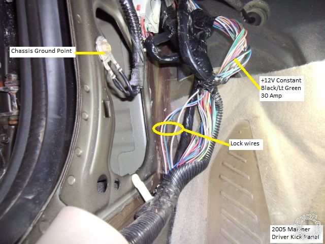
Photo 2 - +12V close up
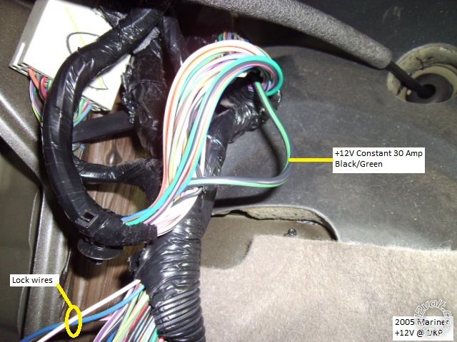
Photo 3 - Lock / Alarm wires close-up
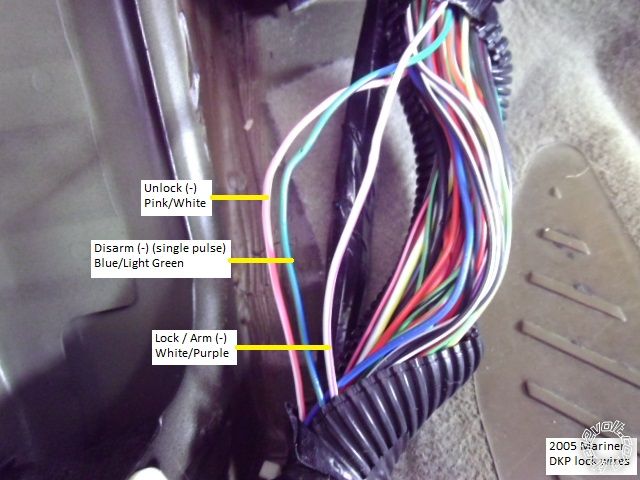
Photo 4 - Steering column - bottom view
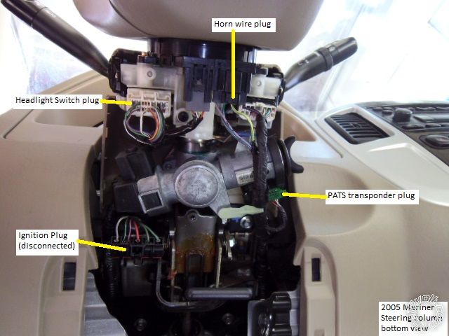
Photo 5 - Horn close-up
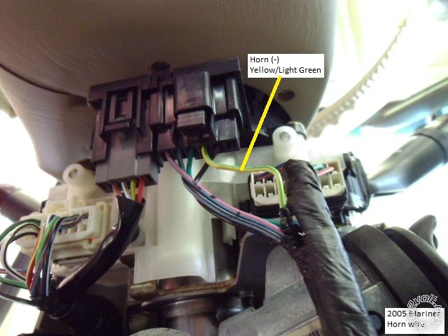
Photo 6 - Parking Lights close-up
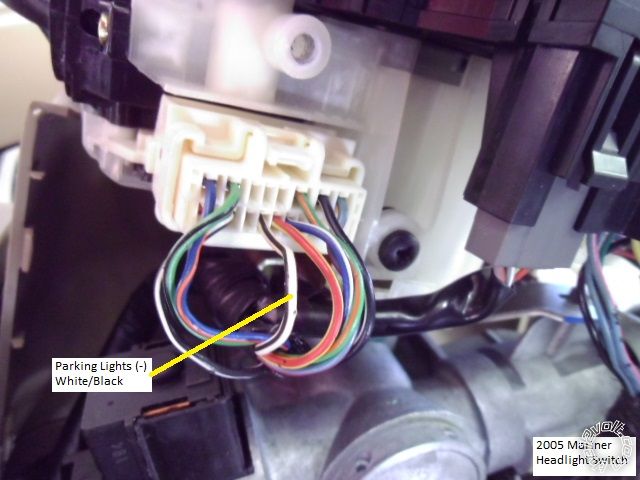
Photo 7 - Ignition connector, unplugged, wire side view
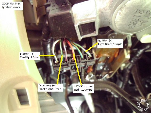
Photo 8 - PATS transponder plug, unplugged
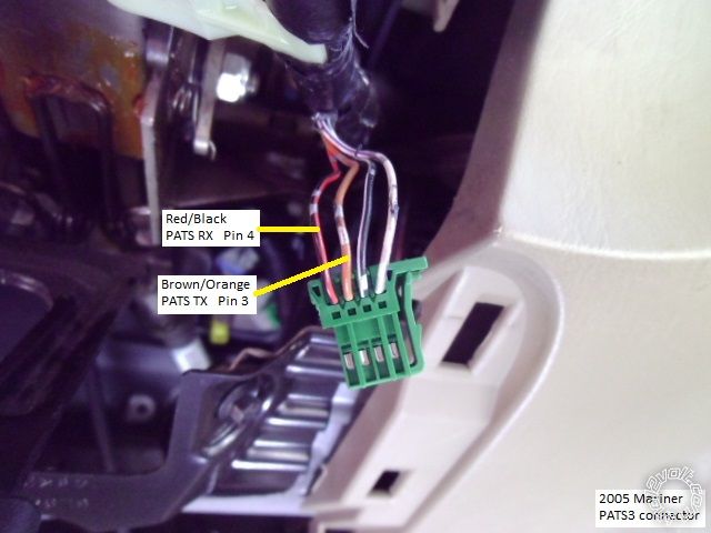
Photo 9 - Tach
Not shown - Brake (+) wire. Photo did not turn out, sorry. The Brake wire is in a two pin Green connector at the
top of the brake pedal. There are two wires in this connector. One is GREEN/ Red and tests as +12V constant, the
other is Light Green and is the (+) Brake wire needed as the Brake input for the R/S.
Even though the vehicles wire harnesses did not have much slack, this is a pretty easy vehicle to do. Figure
about $90 for the R/S & bypass module and a leisurely 5 hours for installation. As always, locate, test and verify
all wires with a Digital Multi Meter before making your quality solder connections.
-------------
Soldering is fun!