1997-2003 Ford F-150 Ultra Start Remote Start Pictorial
Printed From: the12volt.comForum Name: Car Security and Convenience - Alarm/Remote Start Pictorials
Forum Discription: Installer submitted Alarm, Keyless Entry, and Remote Start Pictorials from our Car Security and Convenience forum.
URL: https://www.the12volt.com/installbay/forum_posts.asp?tid=135434
Printed Date: April 19, 2026 at 10:02 AM
Topic: 1997-2003 Ford F-150 Ultra Start Remote Start Pictorial
Posted By: rheckbert3
Subject: 1997-2003 Ford F-150 Ultra Start Remote Start Pictorial
Date Posted: December 02, 2013 at 4:49 PM
Kreg357's Pictorial
These trucks have a PATS1 (Passive-Anti-Theft-Systems) engine disabler. There is a chip in key (transponder key) that interfaces with a transponder in the ignition lock. If a key other than the key with the correct chip is used to start the truck the PATS system prevents the engine from starting.
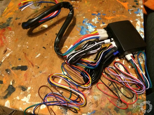
The truck used here was an F150 1999 5.4 Triton with remote keyless entry (RKE) and no factory alarm. The system installed was an Ultra Start U1272 and to bypass the PATS system a Fortin Key-Override-All bypass module was used. Because this truck had Factory RKE it had Type B(-) locks no additional hardware was needed to handle the locks. While trucks with out RKE use Type C (REV) locks will need additional hardware to unlock and lock the locks (451M door lock module)
Once you have the Ultra Start and Fortin bypass module, I would suggest reading and looking over the installation manuals a few times before starting.
Installation:
Insert the key and turn the truck to ON but dont start. Lower the transmission shifter to the lowest gear and remove the upper trim bezel by pulling it straight out from the cluster panel while holding the bottom of the panel. Return the selector to park and remove the key. Push the steering wheel all the way up to the top position to get more room. (You may also want to remove the front drivers seat to get additional room although this is not necessary.
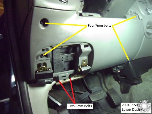
Remove the lower dash panel. First remove the fuse panel door. Then remove 2 (7mm) bolts on each the hood release lever and the emergency brake lever for a total of 4 (7mm) bolts. Then remove 4 (7mm) bolts in the 4 corners of the lower dash panel. Then remove 2 (8mm) bolts directly below the fuse box.
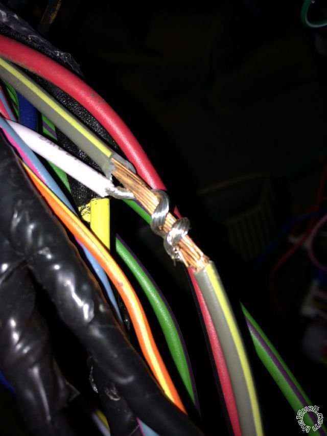
All wire connections being connected in the middle of an existing wire should be spliced in. To splice a wire you should first cut, using wire cutters, two incisions about an inch apart in the wire where you want to splice. Then you should use a razor blade to remove half the wire between the two incisions. Then remove the rest of the insulation. Then using something pointy, you should split the wire in half evenly making a sort of eye in the middle of the wire. Then put the wire that is going to be spliced in through the hole and then continue to wrap the wire around the other wire and make a good mechanical connection. To insure you have a good electrical connection solder should be used. And then wrap this with electrical tape very tightly.
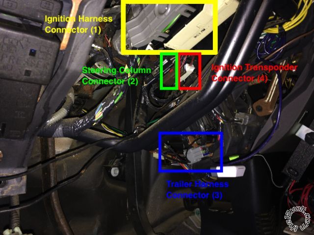
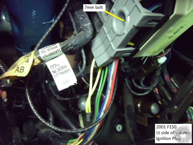
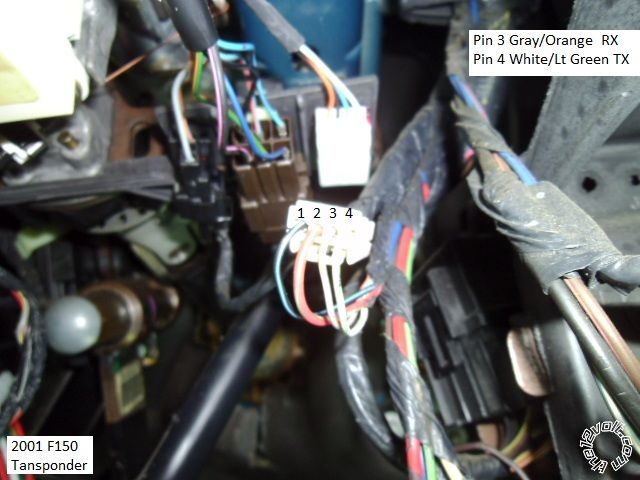
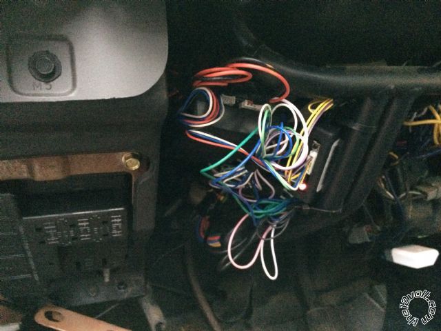
Here is a picture of the 4 connectors that will have to be spliced into. (1) This gray connector is the main ignition connector. It is held in place by a single (7mm) bolt. (2) This brown connector is the steering column connector. (3) The smaller gray connector is the trailer harness connector. (4) The white connector is the ignition transponder connector
(1) First to remove the ignition connector you must remove a (7mm) bolt from the center of the connector. Then pull out the connector. Once you get the connector out remove some of the tape about 6 inches down. And remove the gray plastic cover to expose the wires. This plastic was very brittle and the legs broke very easy. Oh well. Here is where you must make connections to 7 wires out of the U1272.
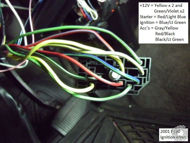
The 2 solid yellow truck wires carry constant 12v+
The RED / blue truck wire is the starter wire. This wire has 12v+ only when the key is in the start position and not in any other position.
The gray / YELLOW truck wire is an ignition 2 wire
The blue/light green truck wire is the ignition wire and has power in the ignition position.
The BLACK/ green truck wire is an accessory wire and has 12v+ in the accessory position and ignition position
From the 6 pin connector on the U1272 you should
A) Splice the yellow starter wire into the RED / blue wire.
B) Splice each of the two 12v+ Fused red power wires into each of the separate 12v+ constant yellow wires on the truck.
C) Splice the white wire into the gray / YELLOW wire
D) Splice the blue ignition wire as well as the yellow Fortin Bypass Ignition wire into the trucks blue/green wire
E) Splice the green accessory wire into the BLACK/ green truck wire.
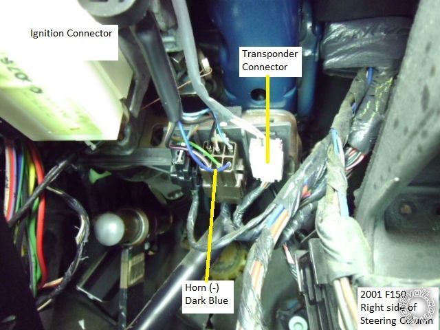
(2) Next the horn connection should be made on the brown connector. On the truck is a dark blue wire going into the brown connector. The WHITE/ blue horn trigger wire from the 9pin U1272 harness should be spliced here.
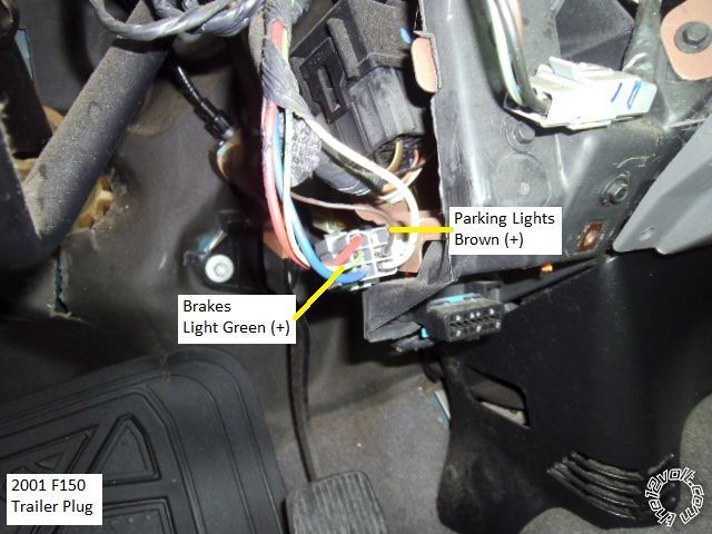
(3) On the small gray connector the park lights and the brake input connections should be made. The pink brake wire from the 9pin U1272 harness should be spliced into green wire in the gray trailer connector. The white wire from the U1272 2pin connector should be spliced into the brown parking light wire on the gray trailer connector.
(4) The white transponder connector has 4 wires. 2 of which are for Rx and Tx of the ignition. These are going to be connected to the Fortin bypass Module (6 pin connector). Connect the
PURPLE / White on the Fortin 6 pin to trucks 4 Pin transponder connector Gray/Orange wire. The yellow/black wire Fortin 6 pin is connected to trucks 4 pin transponder WHITE/ light green wire.
And as mentioned above, the yellow wire on the Fortin 6 pin goes to U1272 6 Pin harness, thick Blue wire (IGN1)
Mentioned below the blue wire on the Fortin 6 pin should be connected to the GWR WHITE/ purple wire on the 3 pin U1272 wire.
The black ground wire on the U1272 2 pin connector must be connected to ground. This can be done by using and eye hook end on the wire and using a self tapping screw into a good metal ground piece.
The blue ground while running wire from the Fortin bypass module 6 pin connector should be connected to the WHITE/ purple wire on the 3 pin connector of the U1272. This is the Ground While Running (GWR) wire. The other two wires red and black on this connector are not used if the bypass module gets it's power from the 4 wire harness (blue, red, black, white) connecting the U1272 and the bypass.
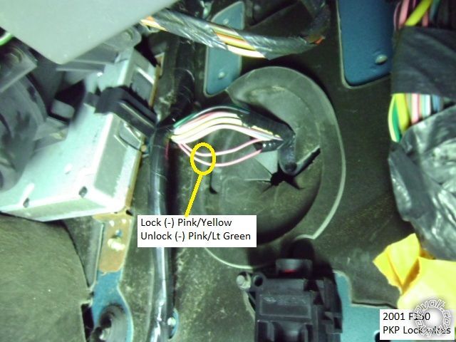
To connect the door locks. The passenger kick panel must be removed. Found down and to the left of the passengers feet. Lift straight back and up to remove this panel. One removed the wiring harness that goes through a big rubber grommet to the door can be seen. Inside this wire harness there is a wire that is pink / YELLOW lock and a pink/green wire unlock. The green and blue wire from the 3 pin U1272 connector must be extended and run over to the passenger kick panel area and connected to these wires. Green to pink / YELLOW for lock and blue to pink/green for unlock.
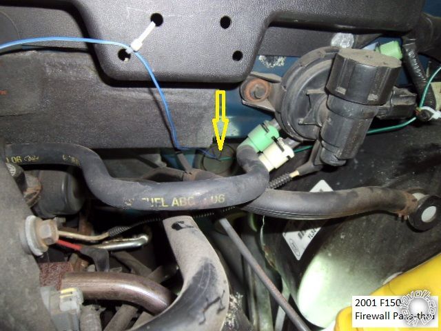
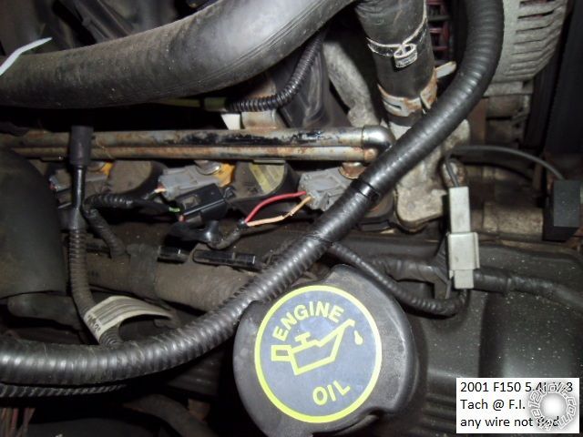
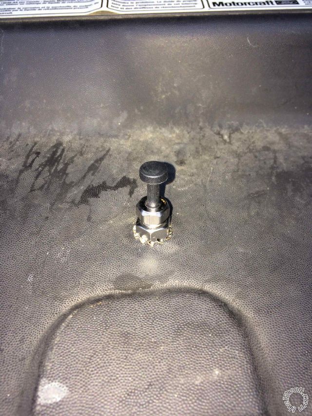
The GREEN / WHITE hood pin and blue/white tachometer wire should be run through the fire wall and into the engine compartment. Just to the left of the gas pedal and up a little but there is a big rubber grommet that can be sliced and these wires can be run into the engine compartment. The GREEN / WHITE hood pin switch should be connected to the supplied hood pin switch to prevent accidental injury. The blue/white tach wire can be connector the any fuel injector wire that is not red. Usually the wire is yellow. This wire should be spliced in like all the rest to the fuel injector wire.
Then you can plug all the connectors in, Following the Fortin and U1272 instructions. Plug in all the connections to the U1272. Then while holding the programming button on the Fortin plug in connector 2 and then plug in connector 1. Then release the button. Turn the key on/off, on/off and back on. Within 10 seconds activate the remote start using the button in the remote. The Fortin bypass is now programmed. If you get 7 light flashes on the truck you are in tach lock out mode and must turn the truck on using the key and let it run for 5 seconds. Then shut the truck off and the remote start should work.
Then you can neaten up all the wires and tuck them up into the area below the steering wheel. There should be plenty of room. And assembly everything back together in the reverse order that you took it apart.
More Information
Ultra Start 1272 Installation Manual
Ultra Start 1272 Owners Manual
Fortin Bypass Quick Sheet
Congratulations. You've just installed a remote start on your truck. Enjoy!
Ricky
Replies:
Posted By: rheckber
Date Posted: December 02, 2013 at 5:04 PM

Posted By: kreg357
Date Posted: December 03, 2013 at 5:17 PM
Excellent job.  Very complete with many good tips!
-------------
Soldering is fun!
Posted By: aldrin
Date Posted: May 21, 2014 at 3:25 AM
thanks
-------------
DRIN
Posted By: rheckbert3
Date Posted: June 19, 2014 at 12:22 AM

I noticed on my Actron 9580A OBD scan tool that I was a getting a NON-MIL Diagnostic Trouble Code P0460 (Fuel Level Sensor 'A' Circuit). So I decided to research this online and found out that this is usually caused by an improperly install Ford remote start system or an aftermarket remote system but could also be a bad fuel level sensor. So I figured it had to be from when I installed the remote starter 8 months ago.
So I found this post on 12volt.
Someone on that thread said that the RED / black wire is not being energized so I figured that was what was happening to me. So I checked over my wiring and noticed I connected the the accessory wires BLACK/ green and grey / YELLOW not RED / black. So today I switch the white wire coming from the remote starter that i originally had connected to the grey / YELLOW wire to the RED / black wire. So now I have the green wire connected to the BLACK/ green wire and the white (2nd accessory) wire connected to the RED / black wire.
Before I switched the wires the instrument cluster gauges took about 12 seconds to "wake up" and after I switched to the RED / black wire the gauges are awake right after the engine cranks. One thing to note is that now that the grey / YELLOW wire is not being powered the ABS light and airbag light are on when the truck is running on remote start but turn off when you insert the key. From what I can determine in the wiring diagrams the BLACK/ green wire powers the radio and windows and wipers. The RED / black wire powers the GEM. The grey / YELLOW wire powers the 4x4 solenoids, airbag monitors, and ABS. I know the wires do much more but these are the main things on each wire.
I believe the P0460 code is set when the truck is using gas but can't detect the fuel level sensor because it is powered from the RED / black acc wire. I think the truck would still pass inspection with the P0460 code but I just wanted to point this out.
Kreg357, (1) should I somehow wire all three accessory wires into the two remote starter accessory outputs? (2) Is it even possible to control three wires with the two from the remote starter? (3) Or is what I have now good (RED / black, BLACK/ green connected and grey / YELLOW not connected)?

I hope this doesn't confuse anyone!
Ricky
Posted By: kreg357
Date Posted: June 19, 2014 at 2:45 PM
Hi Ricky,
There are several ways to power all the vehicle ignition wires ( IGN & ACC ) during a remote start. The Ultra Start unit
can directly supply 2 IGN's & one ACC or one IGN and 2 ACC's. My testing found the F150's wires as:
IGN1 = DARK BLUE/LIGHT GREEN (+)
ACC = GRAY / YELLOW (+)
ACC = BLACK/ LIGHT GREEN (+)
ACC = RED / BLACK (+)
The various wire guide listings have conflicting info. Bulldog has it this way :
IGN1 = DARK BLUE/LIGHT GREEN (+)
IGN2 = RED / BLACK (+)
ACC = GRAY / YELLOW (+)
ACC = BLACK/ LIGHT GREEN (+)
ReadyRemote has it this way ( which does not include the BLACK/ Light Green wire at all ):
IGN1 = DARK BLUE/LIGHT GREEN (+)
ACC = GRAY / YELLOW (+)
ACC = RED / BLACK (+)
Audiovox shows it this way ( with only one ACC and everything else an IGN ) :
IGN1 = DARK BLUE/LIGHT GREEN (+)
IGN2 = GRAY / YELLOW (+)
IGN3 = RED / BLACK (+)
ACC = BLACK/ LIGHT GREEN (+)
The first question is : Does the heat / AC and fans work without the Gray / YELLOW wire powered?
While some vehicles are very particular with IGN and ACC wires, some are not. This means that you could power
all the wires as IGN wires if you battery had enough cranking power to start the engine with all accessory type
circuits powered and possibly running. That is why circuits that draw a lot of current are not powered during
engine cranking ( ACC type circuits ).
Anyway, you could easily set up the Ultra Start to power all the ignition circuits as shown in the Bulldog Security
listing by adding one additional IGN circuit output. You will need a 30/40 Amp SPDT relay with harness and an inline
fuse holder with a 30 Amp fuse. Wire as follows ( Relay Pin 87a is not used ):
Relay Pin 85 to U1272 Black AUX1 wire on 9 Pin plug
Relay Pins 86 and 87 to a suitable +12V constant source through 30 Amp fuse
Relay Pin 30 to F150 RED / Black wire @ ignition switch harness
You must program the U1272 to use its' Black wire as a (-) 200mA Ignition output to control the relay. This is done by
changing Mode 1, Item 5 to Option 1.
The other F150 ignition circuits would be :
U1272 thick Yellow to F150 RED / Light Blue
U1272 thick Blue to F150 DARK BLUE/LIGHT GREEN
U1272 thick Green to F150 GRAY / YELLOW
U1272 thick White to F150 BLACK/ LIGHT GREEN *** Program U1272 to ACC2 ( Mode 3, Item 1, Option 2 )
Done this way, all of the F150's ignition circuits would be powered as per the Bulldog Security wire guide listing.
Kreg
-------------
Soldering is fun!