This is a brief Pictorial for a DIY remote start install on the 2014 Explorer with SA stamped ignition key. The 2011 through
2014 models should be the same, with minor wire color differences on the Transponder Plug. This vehicle was a 80 Bit SA
key, U.S. market XLT version. It had power locks with RKE ( remote keyless entry ) and the Factory Alarm system. The
Push-to-Start vehicles are different and not covered in this Pictorial.
R/S system considerations :
1. The vehicle has a hood pin as part of the Factory Alarm. This signal can be used by the R/S system if the R/S system
can be programmed for a N.C. type hood pin input. ( Signal is ground when hood is closed and goes to an open state
when the hood is raised.)
2. The vehicle has "one-touch-starting". The ECM will control the starter crank time after a brief +12V pulse on the
Starter wire. As such, no Tach connection is needed ( unless you wish to take advantage of the "over-rev" feature
found on some R/S systems ).
3. The vehicle has built-in "Anti-Grind" so there is no need to cut the starter wire to add that R/S feature. Cutting the
Starter wire for "Starter-Kill" is still an option.
4. The Factory RKE systems works normally while the engine is running. A simple "one-button" R/S system will work
well, saving install time and money.
5. Factory Alarm disarm happens automatically with a remote start. ( Ignition, Accessory and transponder bypass. )
There are many good quality R/S systems available that will properly handle these requirements. For this install an
Ultra Start U1172 for chosen. The Avital 4113 is another good R/S system readily available to the DIY'er. The transponder
bypass duties were taken care of with an iDatalink ADS TB module flashed with ADS TB FM3 firmware. Other choices
more suited for the DIY'er are the Fortin EVO-Ride and the XPressKit PKTX due to their "firmware pre-loaded" status. You
will need two, non-clone ignition keys for bypass programming.
Disassembly :
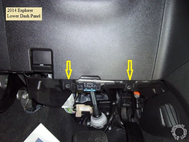
Remove the lower dash panel by removing the two screws indicated and pulling the panel straight away from the dash.
There are several plastic snap retainers. Photo below :
Remove the steering column covers by removing three screws from the bottom and gently separating the two halves.
This will provide better access to the ignition and transponder harnesses and exposes the PURPLE / Green (-) Horn wire
in the steering column, if that feature is desired.
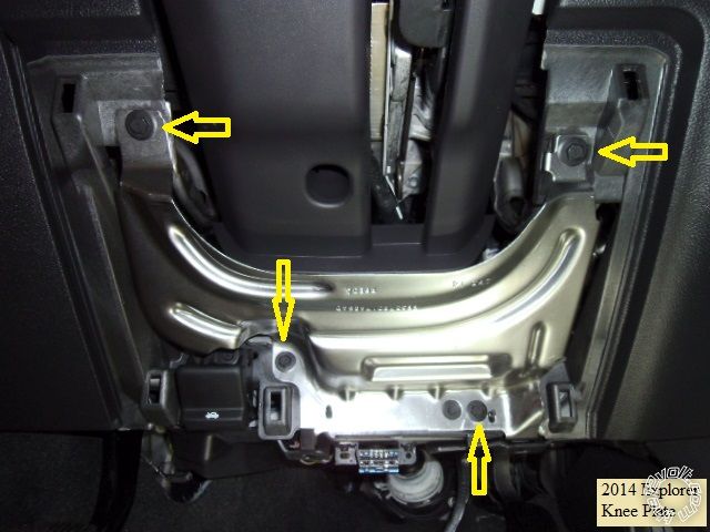
Remove the four screws retaining the knee plate as indicated :
Wiring :
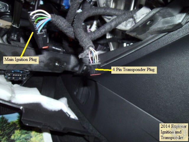
Reach up behind the ignition switch and release / un-plug the main ignition and transponder connectors. Gently pull
them out for testing and wire connections. Here is a photo of these harnesses unplugged :
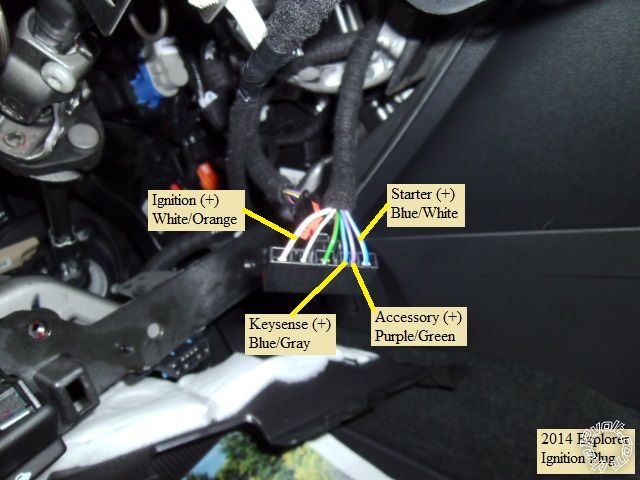
Here is a close-up of the main ignition harness with the wires marked :
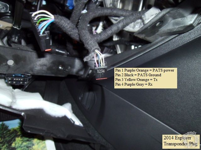
Here is a detailed shot of the transponder connector :
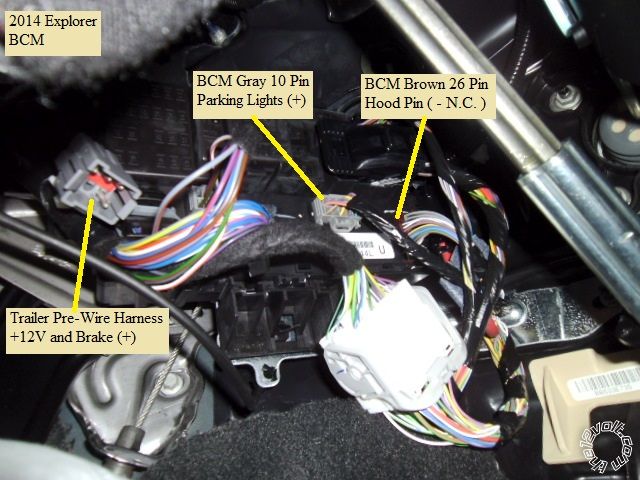
Located behind the E-Brake release handle is the Trailer pre-wire harness. This harness has a convenient +12V 30A
wire and the Brake (+) wire. Just behind this connector is the BCM that has the Parking Light and Hood Pin wires.
Here is a photo :
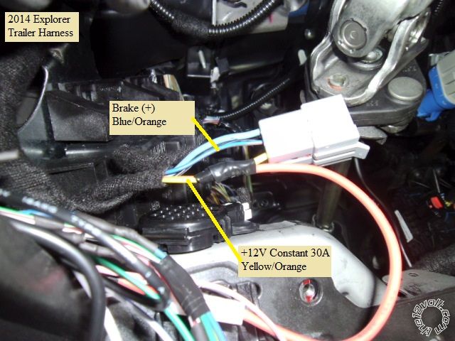
Here is a close-up of the Trailer pre-wire harness :
Here is a picture of the BCM with the Parking Lights and Hood Pin wires indicated :
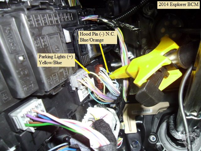
This is a close-up of the Parking Light wire :

Here is the R/S wiring :
U1172
6 Pin Ignition Harness
1 Yellow (+) Starter Output Explorer Blue/White @ Ignition harness
2 Green (+) Accessory Output Explorer PURPLE / Green @ Ignition harness
3 Red (+) +12V constant _____ \ combine wires and connect to
4 Red (+) +12V constant / Explorer Yellow/Orange @ Trailer pre-wire harness Fuse @ 25 Amps
5 White (+) Flex Relay Output Not Used ( or Explorer Keysense Blue/Gray @ Ignition harness )
6 Blue (+) Ignition Output Explorer WHITE/ Orange @ Ignition harness
2 Pin Harness
Black (-) Main Chassis Ground Chassis Ground
White Selectable Parking Light Output Explorer Yellow/Blue @ BCM Gray 10 Pin Plug ** Set jumper to (+)
9 Pin Harness
1 Yellow (-) Rearm Output Not used
2 Brown (-) Disarm Output Not used
3 Black (-) AUX1 Output Not used
4 RED / White (-) Trunk Release Not used
5 WHITE/ Blue (-) Horn Output Explorer PURPLE / Green @ steering column ( optional )
6 Pink (+) Brake Input Blue/Orange @ Trailer pre-wire harness
7 GREEN / WHITE (-) Hood Pin Input Blue/Orange @ BCM Brown 26 Pin Plug *** Program to N.C. input
8 Blue/White (AC) Tach Input Not used
9 Blue (+/-) Glow Plug/WTS/Trigger Input Not used
Lock Harness
Green (-) Lock Not used
Blue (-) Unlock Not used
3 Pin Bypass Harness
Red +12V ADS TB Red @ 4 Pin
Black Ground ADS TB Black @ 4 Pin
WHITE/ Violet (-) GWR ADS TB Blue/White @ 4 Pin
Follow ADS TB FM3 Type 1 install wiring for Explorer transponder plug connections. Be aware that programming the
U1172 with a two button remote is challenging, a four button remote can be temporarily programmed/paired and used.
Because the ignition wires are thin gauge and do not require a lot of current, you can combine the R/S +12V power wires
into one wire, fused at 25 Amps. There is plenty of space under the dash for the R/S system. As always locate, test and
verify all vehicle wires with a DMM prior to making quality soldered connections.
-------------
Soldering is fun!
What we were discussing earlier, Euro versions don't have the transponder plug adjacent to the ignition. Need a key in a box by-pass.
That wire covering looks like the fabric backed Tessa tape as used on BMWs.
Also we'd use a BROWN / yellow (-) haz control from the alarm.
-------------
Amateurs assume, don't test and have problems; pros test first. I am not a free install service.
Read the installation manual, do a search here or online for your vehicle wiring before posting.
What kind of tool is that with the yellow front? DMM or something else for testing? If it was a wire stripper for inline soldering I was gonna buy on immediately
-------------
'08 Tundra CM, 4wd, 5.7L, Mickey Thompson 35's
It's a test lead from a DMM, known as a "bed of nails".
-------------
Amateurs assume, don't test and have problems; pros test first. I am not a free install service.
Read the installation manual, do a search here or online for your vehicle wiring before posting.
The Bed-of-Nails is a probe attachment that makes probing wires with a Digital Multi Meter fairly easy.
The yellow handled probe shown in this Pictorial is called a CircuitBuddy. More info and a link to the manufacturers WEB site is
found in a short discussion at the end of this Pictorial : https://www.the12volt.com/installbay/forum_posts.asp?tid=133496
Both are handy tools that when used correctly make the install easier.
-------------
Soldering is fun!