2013-2014 Accord Remote Starter Install Pictorial
Printed From: the12volt.com
Forum Name: Car Security and Convenience - Alarm/Remote Start Pictorials
Forum Discription: Installer submitted Alarm, Keyless Entry, and Remote Start Pictorials from our Car Security and Convenience forum.
URL: https://www.the12volt.com/installbay/forum_posts.asp?tid=137247
Printed Date: May 23, 2026 at 9:39 PM
Topic: 2013-2014 Accord Remote Starter Install Pictorial
Posted By: kreg357
Subject: 2013-2014 Accord Remote Starter Install Pictorial
Date Posted: September 13, 2014 at 10:03 AM
This R/S w/Keyless Entry Pictorial is on the 2013 & 2014 Honda Accord and covers the LX and Sport models that use
the standard key ignition system and is intended for advanced DIY'ers. It does not cover the Accord's with "Push to
Start" ignition systems.
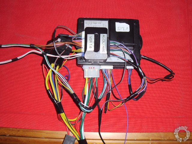
For this install a Compustar CM6200-s and an ADS AL-CA bypass module flashed with the DL HA6 firmware was used.
W2W mode connections were made between the CM6200-s and ADS AL-CA. Semi-finished bench prepped unit :
The install guides for the available bypass modules are very good and should be used as your primary reference. As
such, this Pictorial will be slightly redundant but will provide some additional useful photo's and information.
While you could do this vehicle with the Valet key in a universal "key-in-the-box" style bypass module and hard wire
everything, using a full featured bypass module like the EVO-ALL or the ADS AL-CA ( or OEM offspring ) has many
advantages. The big negative is the need for the ADS USB or Fortin FlashLink cable to perform the necessary KLON
or DCryptor process. If you are a DIY'er, please visit the Fortin WEB site ( https://fortin.ca/en/ ) and do some research
before attempting this install. Due to the additional equipment and WEB site access required, this is really a professional
or very advanced DIY'er install.
In the U.S. market vehicles, the LX and Sport models come with a Factory Alarm. This is good and bad. The good
part is the factory hood pin can be used by the R/S system, the bad part is you must incorporate alarm arm and
disarm into the R/S install. Using a full featured bypass module makes this very easy. Additionally, Honda turns off
the factory remotes while the engine is running, so a R/S system with keyless entry is highly recommended.
Let's start taking the vehicle apart :
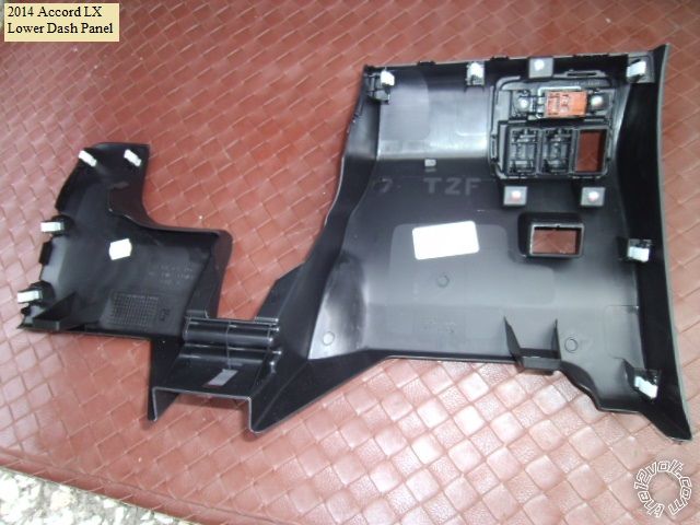
Remove the lower dash panel by pulling it straight away. There are many plastic clips that hold it in place as shown
in the photo below :
Next comes the steering column covers. Release the upper cover with a non marring tool. Pictures below :
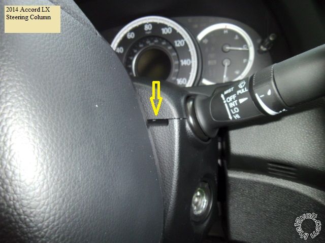
Once the upper cover is raised up, you can remove the lower cover retaining screw's at the 10 and 2 o'clock positions.
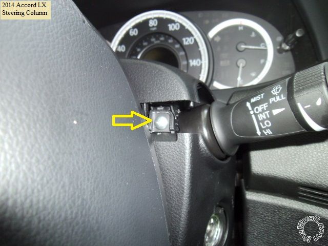
Finally, remove the lower cover retaining screw at the underside as indicated in the photo below :
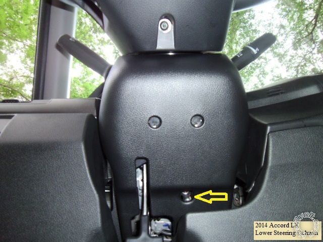
You now have access to all the necessary wires.
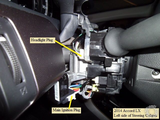
Here is a picture of the left side of the steering column with the important connectors marked :
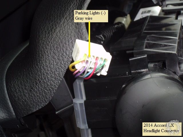
This is a close-up of the Parking Light wire ( connector unplugged ) :
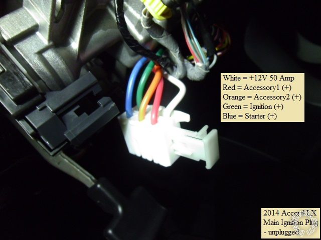
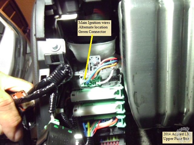
Here is a shot of the main ignition harness ( connector unplugged ) :
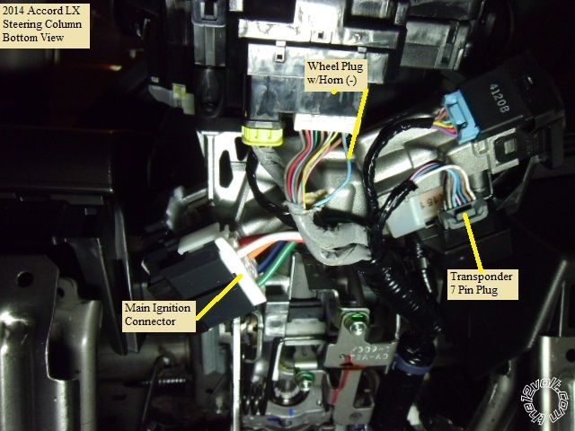
Next is picture of the underside of the steering column with the important connectors marked :
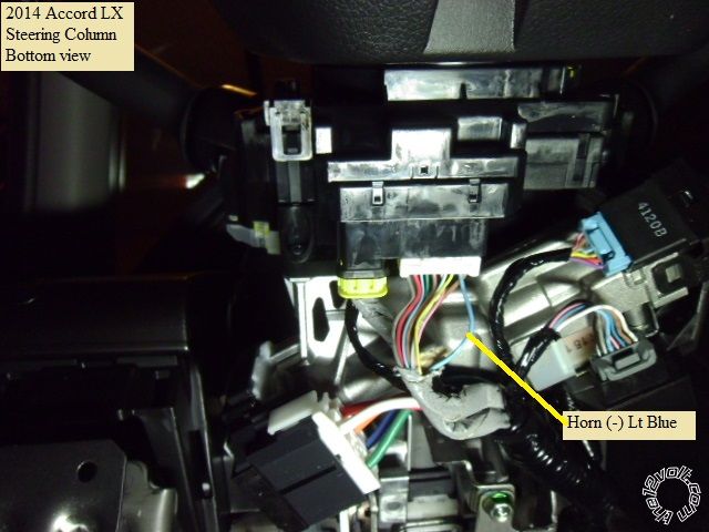
Here is the ( optional ) horn wire :
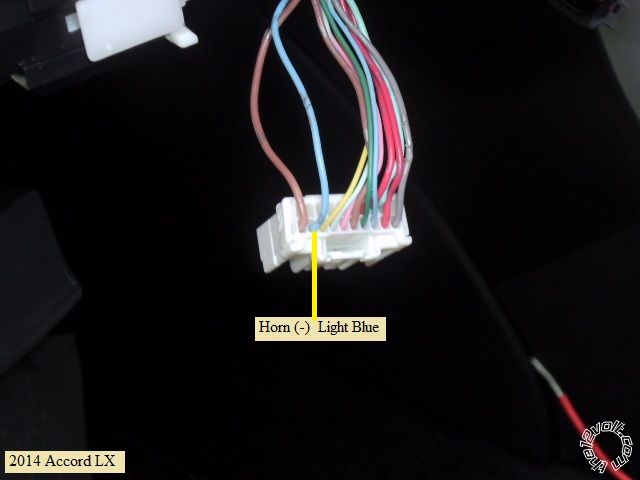
and a close-up of the horn wire :
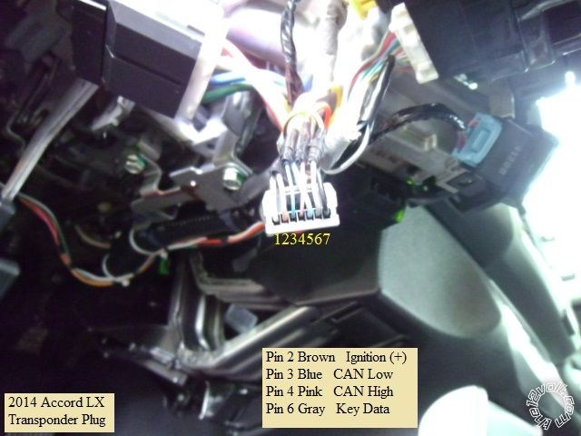
This is a photo of the transponder connector with the wires marked : ( the bypass install guides have better photos )
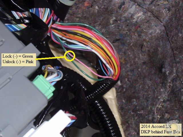
The easiest location to catch the lock wires is in the harness coming from the door, as it goes up the DKP to the
back of the fuse box. Here is a picture :
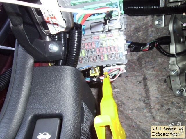
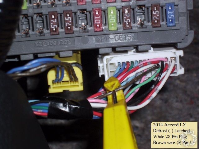
Bonus wires : The rear defroster can be controlled by the R/S system using a (-) latched output and the wire shown :
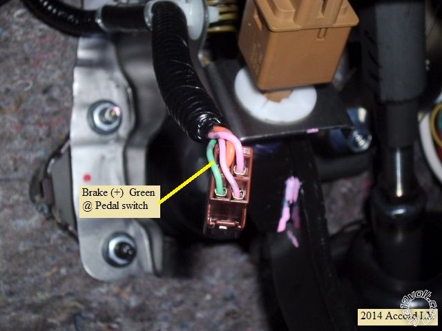
Brake wire :
A few notes and tips...
The regular key start Accords do not have "one-touch" starting or built in anti-grind. Running in Tach mode is
recommended. Adding anti-grind as an additional cost feature is a nice option. Due to the tilt / telescopic steering
wheel, making all the ignition connections at the steering column connector is problematic and requires careful
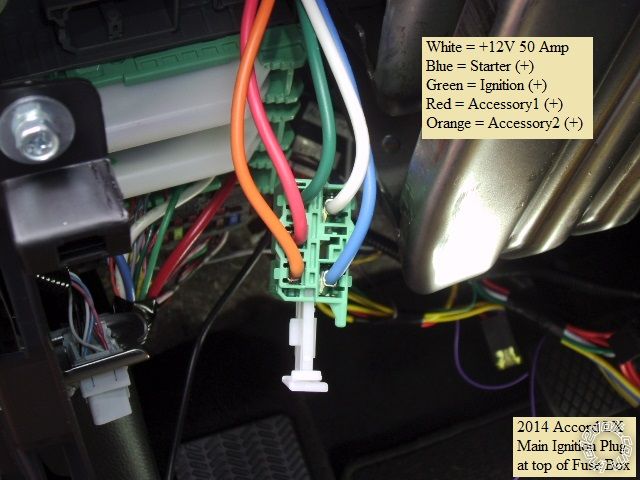
wiring. Personally, I prefer to make the ignition wire connections at this connector, above the fuse box :
Be aware that the door locks work differently while the engine is running. With the engine off, the R/S FOB will act
like the factory FOB and provide progressive unlock. While the engine is running, the bypass module controls the
lock more directly, using the vehicle lock wires shown above. With the engine running, an unlock from the R/S FOB
will unlock all doors at once.
Also, while not mentioned in the bypass install guides, the trunk release from the R/S FOB will not function while the
engine is running ( just like the factory FOB's ).
The drivers door will unlock during a remote start ( to turn off the factory alarm ) so you must set up the R/S system
or bypass module to do a lock after remote start.
There is plenty of room under the dash for module placement. Good, solid ground screw / bolt locations are abundant.
Using a full featured bypass module eliminates the need to pass any wires through the firewall.
Note : All wires should be located and verified with a Digital Multi Meter prior to making your quality soldered connections. 
------------- Soldering is fun!
Replies:
Posted By: smokeman1
Date Posted: September 13, 2014 at 8:31 PM
Absolutly fabulous. You do great write ups.
-------------
When all else fails, Read the Instructions
Support the12volt.com Make a Donation
Posted By: prdjr165
Date Posted: January 03, 2015 at 2:19 PM
did one today with a Compustar CM5000 and Blade-AL..EASY !This info is spot on !
Posted By: redknights
Date Posted: January 29, 2015 at 8:58 AM
Thanks for the great write up. I have few questions about the install. I'm going to get the Viper 4806 2-way, ADS AL-CA and USB cable for programing. I've a 2014 Accord Sport, STD key, & AT, so I'll follow Type 1 install. If I use the Data Mode cable from RS to iDatalink, do I need to worry about the other Red or dotted line connections from RS to iDatalink? Type 1 didn't mention anything about connecting to the Main harness for 12v, starter, ignition and acc. Do I need to worry about it? I do want a connection to defrost and see the brown wire connection. I also got an account to access iDatalink to flash the firmware, will I also have access for extended programing?
Posted By: kreg357
Date Posted: January 29, 2015 at 11:34 AM
The Viper 4806 and ADS AL-CA will work well for this install. Having the ADS USB cable and access will make things easy for
you to do the KLON portion of the bypass programming. A few things to point out :
1. If you haven't ordered the ADS AL-CA bypass module, see if you can get a FLCAN module. It is the same thing but will have
the proper D2D harness for the connection between the Viper and the bypass module. If you already have the ADS AL-CA,
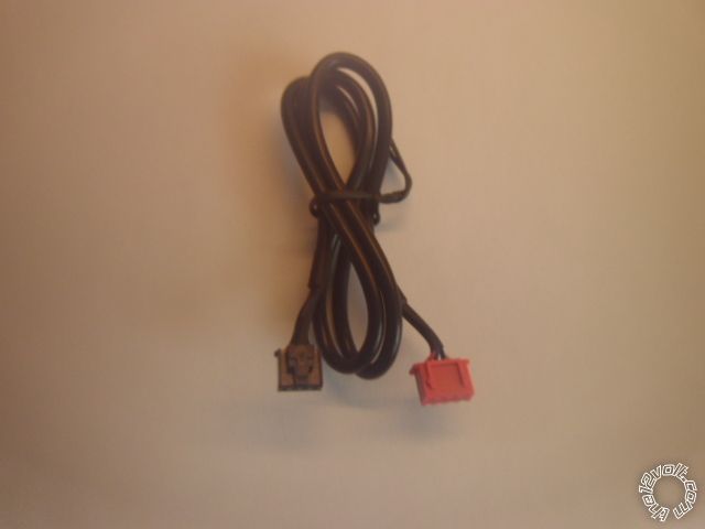
check the package of harness for the D2D cable that has the proper Red connector on one end. If you don't have it, you can
get one online ( EBay ) for ~ $5, or go in W2W mode like shown in the Pictorial. The D2D harness looks like this :
2. Connect the USB cable to the PC and the bypass module and sign-on. The Flash program should recognize the module and
show you the current firmware and S/N of the bypass module.
3. Go through the process of selecting the vehicle. When you get to the point of selecting the Installation Mode, be sure
to select DBI ( this happens automatically with a FLCAN module ).
4. On the next page select the DL version of firmware for the flash. This is the full featured version that does everything, not
just the transponder bypass.
5. You can configure features but the defaults are normally satisfactory. Remember to download the install guide at this point.
The current guide is #19147 for the ADS AL-CA or #19148 for the FLCAN.
As you mentioned, using the Type 1 install, the D2D harness will handle all the Red dashed lines, so only the necessary Black
solid lines have to be hardwired. While I don't do D2D, it is interesting that there are differences between the Type 1 diagram
with the ADS AL-CA and the FLCAN. Anyway follow the appropriate guide. Follow the Installation Mode Selection process
shown at the top of Page 25 to select DATA ( one blink ) and lock it in.
The bypass module install diagram concerns itself with only the connections that it needs / uses / controls. It does not go into
detail about the R/S's connections. It's generic that way and really can't cover all the different makes and models of R/S systems
it can work with. For your Viper install you will still need to connect the following wires :
H/1 Red
H/2 Black
H/3 Brown optional
H/5 White *set jumper to (-)
Remote Start, 8-pin connector - All wires except pin 2 are connected to the vehicles ignition harness as shown in Pictorial
1 RED / BLACK (+) 12VDC CONSTANT INPUT White
2 PINK/BLACK (+) FLEX RELAY INPUT 87A not used
3 PINK/WHITE (+) IGNITION 2 / FLEX RELAY OUTPUT Orange ** Connect to ACC2 / program Viper to ACC2
4 RED (+) 12VDC CONSTANT INPUT for ignition 1 relay White
5 VIOLET (+) STARTER OUTPUT Blue
6 ORANGE (+) ACCESSORY OUTPUT Red
7 RED / WHITE (+) 12VDC CONSTANT INPUT White
8 PINK (+) IGNITION 1 INPUT/OUTPUT Green
Auxiliary/Shutdown Harness 24-pin connector
2 Blue/White *** use for Defrost and program to Latched output
12 Violet/White ****Might be required if Viper can't handle Tach via D2D harness
13 BLACK/ White chassis ground
Good luck with the install!
------------- Soldering is fun!
Posted By: redknights
Date Posted: January 29, 2015 at 3:20 PM
Thanks for the detailed info. I didn't get anything yet, but I'll order the FLCAN, USB cable and Viper within the next few days.
Posted By: redknights
Date Posted: January 31, 2015 at 10:39 AM
One more question about the Viper H/1 Red, I assume that's another 12v connection. Can that also be solder with the white along with the other 3 connections in the ignition harness or should I look for another 12v connection?
Posted By: kreg357
Date Posted: January 31, 2015 at 4:09 PM
With a basic R/S w/ Keyless entry system ( no alarm functions ), the White +12V wire will handle the current. If space along the White wire is limited in one area, you could connect two Viper inputs at the White wire above the fuse box and the other two Viper +12V inputs on that same White wire at the steering column.
-------------
Soldering is fun!
Posted By: redknights
Date Posted: February 02, 2015 at 10:30 AM
A few more questions. I ended up ordering the Viper 4706v so it should be here at the end of the week. Do I also need to get the 998T Bitwriter to program the Viper? Also looking at Type 1 install of the FLCAN. I'm using D2D but there are still a few W2W that I need in their diagram. I need the wire color from the Viper for the E-Brake and Trunk Status.
Viper Aux Harness FLCAN
12 Violet/White to PURPLE / White (Tach)
???(20 Brown) to Green (E-Brake Status)
???(3 RED / White) to Yellow/Red (Trunk Status)
Posted By: kreg357
Date Posted: February 02, 2015 at 11:15 AM
The BitWriter will make changing Viper programming options very easy, but they are pricey at $70. It is possible to make the
necessary option changes with the remotes, just a PITA.
I don't have a Viper 4706V install guide to give the actual harness and pin number but ( 2014 Accord w/AT ) :
FLCAN Tach goes to Viper VIOLET/WHITE TACHOMETER INPUT.
FLCAN Green E-BRAKE STATUS (-) OUTPUT could go to the Viper BLACK/ WHITE (-) NEUTRAL SAFETY INPUT but is not required
due to the Accord's starter safety circuits. The Viper BLACK/ WHITE (-) NEUTRAL SAFETY INPUT should go to chassis ground.
FLCAN YELLOW/RED - TRUNK STATUS (-) OUTPUT is not used. The 4706V is not an alarm system and does not monitor the
vehicle access points ( unless the install vehicle has a manual transmission ). ------------- Soldering is fun!
Posted By: redknights
Date Posted: February 07, 2015 at 5:34 PM
A big THANK YOU to Kreg357 for all of your help!!! I installed the R/S today and it's working great. My only gotcha was the Viper default to Manual Transmission which I need to set to Auto. Your tutorial and steps were spot on.
Posted By: kreg357
Date Posted: February 08, 2015 at 4:29 PM
The iDatalink bypass module integrates well with the Accord. Glad the install went smoothly. 
This info should be accurate for the standard key ignition 2015 Accord's, too. ------------- Soldering is fun!
Posted By: dfarr67
Date Posted: July 11, 2016 at 9:36 PM
Bringing back a lost thread;)
I'm not really into wiring but I struggle on- have had this 2015 honda Accord Sport MT6 for about a year. The dealer added a CM7200 for the remote start in northern Canada (yes it sucks to have two remotes). Would it be right to connect (+ high current) Pin2 GREEN / WHITE to the (-) gray parking light wire shown in the pic at the headlight plug? The head lights were wired to come on when remote started I didn't like the HIDs flashing, I just want the parking lights to come on. Thanks
-------------
Dave Farr
Posted By: kreg357
Date Posted: July 12, 2016 at 6:06 AM
No. You don't want to connect the (+) Parking Light output to the cars (-) Parking Light wire.
Fortunately, Compustar makes it easy for you. On the CM7200 CN5 plug, use the GREEN / WHITE
(-) Parking Light Output wire at Pin 17.
Additionally, if your car has an Auto position on the Headlight switch, you should ensure it is
not in that position when you park the car because if it's dark when you remote start the car,
the headlight switch will "over-ride" the CM7200 and turn on the headlights.
-------------
Soldering is fun!
Posted By: dfarr67
Date Posted: July 12, 2016 at 9:14 AM
Ah yes, that was the 'other' -250ma green and white- to the same grey wire referred to I presume. I don't mind the headlights coming on, I just didn't like the headlights flashing whatever times, hard on the HID ballasts. Thanks
-------------
Dave Farr
Posted By: mhunguyen
Date Posted: October 03, 2016 at 3:13 PM
Quick question Kreg, looking to install this for a 16 Accord. I am 99% sure the wiring is the same as the 14. Question that I had was why are we using Pink/White from the Vipers R/S for the accessory 2 wire in the accord.
Posted By: kreg357
Date Posted: October 03, 2016 at 6:55 PM
Yes, the regular key 2016 Accord should be the same. As for the thick Pink/White wire from the DEI R/S system
going to the Accord's Accessory2 wire, I usually try to duplicate the normal ignition switch functions during a
remote start, so I make that connection. I have never tried it without connecting ACC2. Being as no extra
external relays or wiring are required with your DEI R/S system, it's a easy job. Just remember to program
Menu 3, Item 8 to Option 2. I have heard that some Techs never connect the ACC2 wire on Honda's because "all it
does is extraneous items like radio and power windows". So the choice is yours.
Just checked on Bulldog Security and saw this tidbit of info :
ACCESSORY /HEATER BLOWER 1 ORANGE (+) (MUST use BOTH ACCESSORY wires) @ IGNITION SWITCH HARNESS, WHITE 5-PIN PLUG, PIN 4
ACCESSORY /HEATER BLOWER 2 RED (+) (MUST use BOTH ACCESSORY wires) @ IGNITION SWITCH HARNESS, WHITE 5-PIN PLUG, PIN 3
Unfortunately, there is no reason given for that "MUST use" statement.
-------------
Soldering is fun!
Posted By: mhunguyen
Date Posted: October 06, 2016 at 7:16 AM
kreg357 wrote:
Yes, the regular key 2016 Accord should be the same. As for the thick Pink/White wire from the DEI R/S system
going to the Accord's Accessory2 wire, I usually try to duplicate the normal ignition switch functions during a
remote start, so I make that connection. I have never tried it without connecting ACC2. Being as no extra
external relays or wiring are required with your DEI R/S system, it's a easy job. Just remember to program
Menu 3, Item 8 to Option 2. I have heard that some Techs never connect the ACC2 wire on Honda's because "all it
does is extraneous items like radio and power windows". So the choice is yours.
Just checked on Bulldog Security and saw this tidbit of info :
ACCESSORY /HEATER BLOWER 1 ORANGE (+) (MUST use BOTH ACCESSORY wires) @ IGNITION SWITCH HARNESS, WHITE 5-PIN PLUG, PIN 4
ACCESSORY /HEATER BLOWER 2 RED (+) (MUST use BOTH ACCESSORY wires) @ IGNITION SWITCH HARNESS, WHITE 5-PIN PLUG, PIN 3
Unfortunately, there is no reason given for that "MUST use" statement.
Thank you for that. Just a curiosity question, it doesnt make a difference if we use the vipers ignition wire to connect it to the honda's accessory wire?
Posted By: kreg357
Date Posted: October 06, 2016 at 2:51 PM
Well, the Accord has two Accessory wires, one Red and the other Orange. An Ignition type output from the Viper
is different than an Accessory output. Specifically, the Accessory type output will drop to 0 volts during R/S
engine cranking ( Starter output at 12 volts ) while an Ignition type output will remain at 12 volts. If you
connected a R/S Ignition type output to a vehicle accessory wire & it was very cold & your battery was weak &
you had the heater ON with the fan set to High, the starter might not get enough power to start the engine because
the R/S did not drop power to the fan circuits during cranking like a regular key start up does.
The Vipers Pink IGN1 wire will go to the Accords Green Ignition wire. The Vipers Orange ACC wire will go to the
Accords Red ACC1 wire and the Vipers Pink/White wire will go the the Accords Orange ACC2 wire. If you do the
Viper programming change mentioned above ( Menu 3, Item 8, Option 2 ), that will change the function of the Vipers
Pink/White wire from the IGN2 default to the desired ACC2 output.
-------------
Soldering is fun!
Posted By: mhunguyen
Date Posted: October 06, 2016 at 3:24 PM
kreg357 wrote:
Well, the Accord has two Accessory wires, one Red and the other Orange. An Ignition type output from the Viper
is different than an Accessory output. Specifically, the Accessory type output will drop to 0 volts during R/S
engine cranking ( Starter output at 12 volts ) while an Ignition type output will remain at 12 volts. If you
connected a R/S Ignition type output to a vehicle accessory wire & it was very cold & your battery was weak &
you had the heater ON with the fan set to High, the starter might not get enough power to start the engine because
the R/S did not drop power to the fan circuits during cranking like a regular key start up does.
The Vipers Pink IGN1 wire will go to the Accords Green Ignition wire. The Vipers Orange ACC wire will go to the
Accords Red ACC1 wire and the Vipers Pink/White wire will go the the Accords Orange ACC2 wire. If you do the
Viper programming change mentioned above ( Menu 3, Item 8, Option 2 ), that will change the function of the Vipers
Pink/White wire from the IGN2 default to the desired ACC2 output.
Ahh. got it. that was a very clear and informative explanation. Thanks a bunch
Posted By: sparxx513
Date Posted: January 12, 2017 at 6:24 PM
Is there a big difference in doing this install on a PTS 13 accord? Ill be using the idatalink AL-CA
Posted By: kreg357
Date Posted: January 13, 2017 at 4:35 AM
Major differences. Disassembly is the same and the Parking Light wire is the same. Other than that, not much.
The regular ignition key Accord has a standard ignition cylinder with the normal ignition wires. The PTS Accord
does not have an ignition cylinder nor these common ignition wires. Instead, the PTS Accord has a Smart PCU module
that controls things. All of the wires found at and used by the R/S & ADS AL-CA are thin gauge. You will want to
cut those thick R/S ignition wires and add similar color ~20 gauge wires to make the run and connections at the
Smart PCU. This will make soldering easier and everything neater and more compact.
Other differences is that the car must shutdown the remote started engine as soon a door is opened. That's just the
way it must be on these cars to reset the computer, etc. Most customers get used to it and don't mind re-starting the
engine once inside the car.
Your best bet is to follow the bypass module install guide to the letter, verifying all vehicle wires for color and
pin location ( and DMM test for non-Data wires ).
-------------
Soldering is fun!
Posted By: sparxx513
Date Posted: January 13, 2017 at 6:14 AM
Appreciate the good info Kreg. I was reading over the AL-CA manual and there was the note there also about the required shut down. Guess that's something they will have to live with if they want a remote start.
Posted By: sparxx513
Date Posted: January 13, 2017 at 6:15 AM
One more thing. How accessible is the smart module that all my wires have to go to?
Posted By: sparxx513
Date Posted: January 13, 2017 at 6:24 AM
Whats your preferred method with these idatalink bypasses? Hardwired or data? Ive always used the hardwired install method, but the data seems like it could save alot of time.
Posted By: kreg357
Date Posted: January 13, 2017 at 8:03 AM
The Smart PCU is fairly accessible to the left of the steering column, much better than the CR-V's that is behind the glove box.
As for W2W or D2D, it usually depends on the R/S unit and how much 2 way traffic is going on between them. I still prefer
W2W for most of my installs but D2D is becoming a viable option due to the improvements over the years. The best route is
a Compustar R/S and a Blade cartridge. Quick, easy, neat and compact.
-------------
Soldering is fun!
Posted By: crazyboom
Date Posted: March 05, 2017 at 4:32 AM
Thanks for the information!!!
If you have a minute...
I'm installing a 7000AS w/Blade AL(DL) HA6 into a 2015 Honda Accord Sport, 4 cyl., auto trans, std key
The Blade connections are straight forward, thanks to the pictorial!
The 7000AS unit wiring has left me with a few questions...
Here is the high current ignition harness schematic
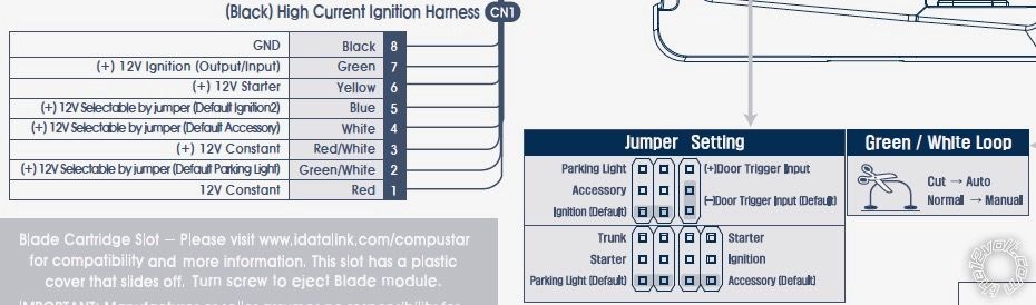
I have from the RS to the Auto:
red to the white 50 Amp
GREEN / WHITE to ???
RED / white to white 50 amp
white to orange?
blue to red? (change jumper to create ACC#2)
yellow to blue
green to green
Black to chassis ground
The GREEN / WHITE is for:
"Pin 2 GREEN / WHITE - Programmable Output: This positive (+) parking light wire triggers
when you lock, unlock, remote start, or during troubleshooting diagnostics. Note: This output is
programmable and can provide a 2nd starter or (+) trunk release output. This is
achieved using Jumpers located under the access door on top of the control module."
What should I wire this GREEN / WHITE wire to? I'm sure I'll need diagnostics at some point or another, so parking light connection is desirable ... The Blade has an auto light control, but from what I've read it's nothing to do with the parking light wire...Bulldog security lists a red wire at the Dash Fuse Box green 44 pin plug at pin 31 as being the parking light (+). is that correct and is that where you'd "tap" into it?
I noticed Bulldog Security lists the ACC wires opposite of what you've listed: orange as 1 and red as 2...does it matter as long as both are connected?
Many thanks for your time!!!
Posted By: kreg357
Date Posted: March 05, 2017 at 5:26 PM
Seems that they have made some updates to the firmware. The locks are handled a bit differently. Follow the Blade w/ HA6
Type 1 install diagram.
Compustar description Accord
red +12V power in to the white 50 Amp
GREEN / WHITE (+) Parking Light not used. Use the Accords (-) Parking Light wire. Info below.
RED / white +12V power in to white 50 amp
white ACC1 to orange
blue ACC2 to red (change jumper to create ACC#2)
yellow Starter to blue
green IGN1 to green
Black Chassis Ground to chassis ground
ACC1 and ACC2 ( Red and Orange ) don't matter which R/S wire powers them, as long as both get power.
Use CN5 Pin 17 GREEN / WHITE (-) Parking Light output and connect to the (-) Parking Light wire shown in Pictorial.
-------------
Soldering is fun!
Posted By: crazyboom
Date Posted: March 05, 2017 at 6:02 PM
THANKS! If you're ever around the Jersey shore I owe you a few beers.
I'll do as suggested.
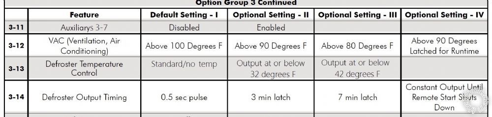
I'd like to use the defrost/auto temp defrost as one of the POC's. Can I use the ADS-USB to designate the wires I use, and then change the defrost and duration in the options menu, or do I require the use of an OP500?
"3-13 Defrost output Temperature Control: This feature will determine the temperature at which the
CM7 will provide an output on any POC programmed with setting 17 or 21 (defrost and defrost 2)".
I'll be using POC 1 (pin 1 blue/white wire) for the anti-grind/start kill relay
I'll be using POC 2 (pin 3 white wire) for the horn
How do I designate POC 3 (pin 5 blue/light green wire) as setting 17?
Last thing I'm having trouble with...I'd like to control the windows (Up/Down/vent) with the R/S FOB. Is it best to integrate a module like a T535, or can it be done through the R/S? (I do not have control of my windows with the OEM key or its buttons like previous accord models)
Again, thank you for your time and expertise!
Posted By: kreg357
Date Posted: March 05, 2017 at 8:13 PM
Do you have the Thermistor temp probe? It connects to the CM7000 at CN8. You will need the probe if you wish to control
the Defrost output at certain temps. They usually come in the 2-way RF remote kits.
I believe that you can set those Special Option Group settings when you flash the Blade cartridge. Click on the "Configure
My Starter" tab and scroll down to those groups. Remember to click on "Save Now" in each area that you change before un-
plugging and exiting the program.
There are 2 AUX outputs that you can configure for a specific output time ( 1-99 seconds ) that might be used for window
roll up and down.
-------------
Soldering is fun!
Posted By: crazyboom
Date Posted: March 05, 2017 at 8:27 PM
I have the DAS, siren, and thermister...I plan on installing all of these but I'm not sure where/how to mount the thermister, any experience or ideas?
I'll look at programming when I get back home (Thursday)...I'll make sure I check that specific area and report back...
I'll also look into the aux as a window control...I assume they are (-) and latched...and will need to be connected near either the switches or kick panels...
Posted By: crazyboom
Date Posted: March 10, 2017 at 1:48 PM
Everything is going smoothly with the install. So crazy that I even gave a lot of thought to the thermister...it doesn't mount anywhere! Is sorta hangs from the control unit. I will ensure it isn't exposed to any excessive heat when I final mount the unit.
I have the defrost set to the "auto" mode, but have decided against a window module. I have the AUX 1 programmed to be controlled by one of the POC wires and would like to use that to vent the windows. It's set at 0.5 second pulse, and can be programmed for anywhere from 1-99 seconds. The wire provides a 250 mA (-) negative output. Is there a window module I could tap into, and would this require a relay? If not, would I need to run the wire to all four windows, and or relay for each one???
Thanks for any ideas...
Posted By: crazyboom
Date Posted: April 16, 2017 at 11:20 AM
Got a bit turned around on a friends similar install....
We are using the secondary ignition harness location in the DKP for "high power". When installing the anti-grind relay what end of the wire is the starter side and which is the key side. I don't have my multi-meter to check it ...I believe if I were to cut the wire that the wire that would still be attached to the harness is toward the starter and the "free standing" wire toward the key side, but can't afford to guess....
THANKS for the help!!!
Posted By: kreg357
Date Posted: April 16, 2017 at 2:47 PM
If you are making the main ignition wire connections at the connector above the fuse box shown in the Pictorial,
you are correct. The Blue Starter wire would be cut. Connect the R/S "Key side" on the end on the Blue wire no
longer connected to that White plug and the "Car/Starter side" of the R/S wires to the end of the Blue wire
still going into that White connector at the fuse box.
-------------
Soldering is fun!
Posted By: crazyboom
Date Posted: April 20, 2017 at 9:07 AM
Thanks again for the conformation on the wiring...
Just spoke to my buddy and he is very satisfied with his compustar install. The only concern he has is that the interior dashboard lights have gone to full bright and the "stem" that controls the intensity isn't functioning... He has limited trouble shooting capability and aside from checking the fuses hasn't accomplished much...Has anyone experienced this? My first thoughts are to recheck the fuses and then look into the light wiring. The only light wire that was used was wire "17" and the wire from the control module in the steering column. I'm not sure if it's the wire or something else, but everything else is working as advertised...I'll also take the OP-500 and see if there isn't some type of setting manipulation that will rectify the situation.... All thoughts/ideas are appreciated!!!
Posted By: mhunguyen
Date Posted: August 11, 2017 at 10:48 AM
I finally put the starter on the Honda 2016 (Standard Key) using ADS ALCA(version HA6) and Viper 4806V. Having one slight problem and was hoping someone could help out. The R/S would start the car find, but the remote starter automatically shuts off after around 60 seconds. After it shuts off, it attempted to start up the engine again, however, the engine only cranks and do not start. Just wondering if anyone know what could be wrong? I do not have the hood pin connected yet, so i'm not sure if this is the main cause?
Thanks in advance
Posted By: kreg357
Date Posted: August 12, 2017 at 7:27 PM
The Hood Pin is not the issue. It would prevent the Viper from attempting to crank the engine first time.
A few questions and suggestions...
1. Are you going W2W or D2D between the Viper and the ADS AL-CA?
With D2D, you must flash the ADS AL-CA with the DBI HA6 firmware and set the ADS AL-CA to Data Mode.
If you are going W2W, then either DBI HA6 or ADS HA6 is OK but all connections between the Viper and the
ADS AL-CA would have to be hard wired and the bypass module set to Standard Mode.
2. As for the Hood Pin, the ADS AL-CA will provide that signal from the data it picks up on the Accords CAN Bus.
You should be using this signal as your Vipers Hood Pin input. It is a safety type signal to prevent the Viper
from remote starting the engine while the hood is open.
3. Are you running the Viper in Tach Mode? The ADS AL-CA does supply a nice Tach signal and you should be
using this input and Viper Tach Mode to remote start the car. There might be some Viper programming changes
required along with performing the Tach Learn process.
-------------
Soldering is fun!
Posted By: mhunguyen
Date Posted: August 20, 2017 at 7:41 PM
Hi Kreg,
1 - I am using D2D onthe Viper and ADS AL-CA using firmware HA6 and Diagram 1 based on iDatalink link guide.
2 - Yes, I agree hood pin isn't the issue.
3. Originally, I had the Viper in Virtual Tach mode, but switched it to Voltage mode. How would I be able to connect the tach between the Viper and ADS ALCA? I would need to connect the Viper Tach Input (VIOLET/WHITE) to ADS ALCA purple/white wire?
I soddered all the wires and right now have a problem with the starter. When I start the car using the Remote Starter, it starts. However, when I start using the Key, it does not start. What could cause this issue? I'm think it could be an issue with the ignition wires. Right now I have the vehicle's ignition wire (Green) cut and the connector side is connected to ADS ALCA WHITE/RED and PINK. The Vehicle's Connector side is connected to ADS ALCA WHITE/BLACK and to Viper's Ignition wire (Pink)
Thanks in advance for the hep
Posted By: kreg357
Date Posted: August 21, 2017 at 9:04 PM
Well, lets go slow so we don't overlook anything.
First the ADS AL-CA should be flashed with the DBI AL(DL)-HA6 firmware. The ADS AL(DL)-HA6 firmware
is not compatable with your Viper 4806 in D2D mode.
Next, the ADS AL-CA must be set to Data Mode as shown at the top of Page 27 of the Install Guide ( #4543 ).
After that the actual bypass to vehicle programming can be done.
As you mentioned, you will be following the Type 1 Install diagram. Of major importance is the fact the the D2D
harness connection will handle all of the dashed Red lines shown. Only the necessaary solid Black lines are
hardwired.
This means that the Tach signal created by the bypass module will be passed to the Viper 4806 via the D2D harness.
Once the bypass module is programmed to the car, this Tach signal can be used by the Viper to properly control its'
Starter output signal length to start the engine. Of course the Viper should have the Tach Learn process completed
successfully before attempting a remote start. Here is the process :
Learning the Tach (not needed with Virtual Tach)
To learn the tach signal:
1. Start the vehicle with the key.
2. Within 5 seconds, press and hold the Control button.
3. After 3 seconds the status LED on your Control Center lights constant when the tach signal is learned.
4. Release the Control button.
Important: This unit can learn the tachometer with the analog input or through D2D
using an interface module. The unit confirms which source is used by flashing the
parking lights.
When programming tach learning with:
Analog, the parking lights flash one time.
D2D interface module, the parking lights flash twice.
If the tachometer input on the system is connected to the vehicle, the D2D tachometer input is ignored
Notice that the ADS AL-CA has a Hood Status output wire shown in dashed Red. This means that this signal
is passed to the Viper via the D2D harness. It's there and the Viper should see and use it. If the hood is open,
the Viper will not attempt a remote start up.
The same thing holds true for the bypass modules EBrake status output. It is automatically supplied to the
Viper. The Viper uses this signal as it's Neutral Safety input and will not attempt a remote start unless the
EBrake is engaged.
You have me a bit confused by this statement : " Right now I have the vehicle's ignition wire (Green) cut and
the connector side is connected to ADS ALCA WHITE/RED and PINK." I have the feeling that you have
made a big mistake here. Please remember that there are two connectors at the ignition switch. The main
ignition wires are in one 6 Pin connector and are all thick ( 12 gauge wires ). These wires get the thick ignition
wires from the Vipers Remote Start, 8-pin connector. The other connector at the ignition switch, has 7 pins and
is the one that has thin gauge wires ( includes the CAN High and Low wires ) and is used by the ADS AL-CA. This
thin Ignition wire gets cut and has the wires you mentioned above connected. This thin Ignition wire is Brown, not
Green.
So, here are the highlights.
1. The ADS AL-CA must be flashed with the DBI firmware and you will use the corresponding DBI install guide.
2. The ADS AL-CA must be set to Data Mode after the firmware flash and prior to vehicle programming.
3. The Tach, Hood and EBrake signals are automatically supplied to the Viper.
4. The Viper should be programmed to Tach Mode ( Menu 3, Feature 2, Option 4 ) and the Tach Learn process
must be run.
5. There is no need to cut any of the vehicles thick ignition wires ( unless you wanted Starter Kill /Anti-Grind ).
6. Ensure you are making the ADS AL-CA connections on the correct 7 Pin ignition switch connector.
-------------
Soldering is fun!
Posted By: maikoatx
Date Posted: August 24, 2017 at 11:28 PM
pts accord, there a way to bypass the honda setup n remote start your car, get in n drive. 2013 to 2015.
-------------
maiko
Posted By: kreg357
Date Posted: August 25, 2017 at 8:23 AM
maikoatx wrote:
pts accord, there a way to bypass the honda setup n remote start your car, get in n drive. 2013 to 2015.
Not that I am aware of. All bypass modules available for the Accord PTS vehicles ( from Fortin, iDatalink and XpresKit ) have that limitation. ------------- Soldering is fun!
Posted By: mhunguyen
Date Posted: August 28, 2017 at 1:23 PM
Thanks for the detailed reply Kreg. I am currently working through the trouble shooting steps at the moment. I noticed that based on your picture, you have Orange as ACC2 and Red as ACC1. However, Bulldog security has ACC1 as ORANGE and ACC2 as RED. I'm not sure if it matters, but just wanted to confirm with you.
Posted By: kreg357
Date Posted: August 28, 2017 at 8:29 PM
mhunguyen wrote:
Thanks for the detailed reply Kreg. I am currently working through the trouble shooting steps at the moment. I noticed that based on your picture, you have Orange as ACC2 and Red as ACC1. However, Bulldog security has ACC1 as ORANGE and ACC2 as RED. I'm not sure if it matters, but just wanted to confirm with you.
Doesn't matter which ACC is labeled as ACC1 or ACC2. The R/S unit will supply identical outputs for that type ignition wire. Just ensure the unit has the Pink/White Flex wire programmed for ACC2 output. ------------- Soldering is fun!
Posted By: mhunguyen
Date Posted: August 28, 2017 at 9:01 PM
Thank you. Everything is working now. Except I can't really get the Viper to learn the Tach. I followed the instruction, but the engine still shuts off after 30 secs of starting. It would then attempt to crank, but the engine does not start. Right now i have it set to voltage mode and it seems to be working fine at the moment. Not sure if it will any issue during the winter.
Posted By: kreg357
Date Posted: August 29, 2017 at 5:55 PM
Not sure why Data Tach is not working. You could try hardwiring it from the ADS AL-CA Tach output to the Viper Tach input and then do a Tach Learn. Or you could go directly from the Viper Tach Input hardwired to an engine F.I. or coil wire. I like to run in Tach Mode. Always works, no matter the temperature.
-------------
Soldering is fun!
|