1999-2004 Jeep Grand Cherokee Remote Start Pictorial
Printed From: the12volt.comForum Name: Car Security and Convenience - Alarm/Remote Start Pictorials
Forum Discription: Installer submitted Alarm, Keyless Entry, and Remote Start Pictorials from our Car Security and Convenience forum.
URL: https://www.the12volt.com/installbay/forum_posts.asp?tid=137527
Printed Date: April 27, 2026 at 5:37 PM
Topic: 1999-2004 Jeep Grand Cherokee Remote Start Pictorial
Posted By: kreg357
Subject: 1999-2004 Jeep Grand Cherokee Remote Start Pictorial
Date Posted: October 25, 2014 at 8:12 AM
Here is a Pictorial for a quick & easy remote start with keyless entry on the 1999 - 2004 Jeep Grand Cherokee.
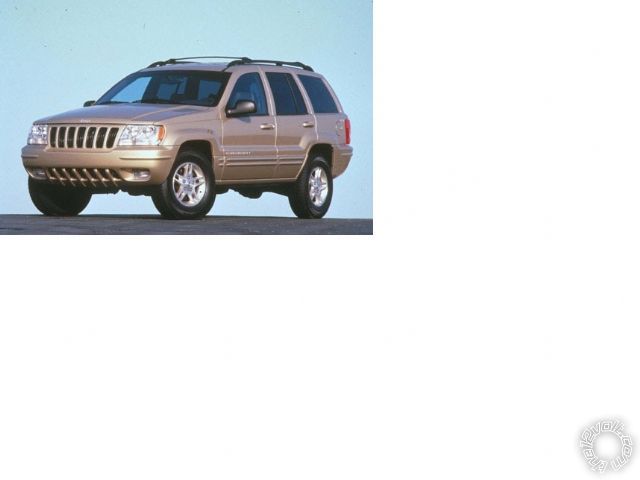
Starting with the 1999 model, a transponder based ignition immobilizer system was in use. Not all G.C.'s had
one. The quick test is to check the ignition key, if it's Gray you have the transponder chipped key and system.
A Black ignition key indicates a non-transponder vehicle. The vehicle in this Pictorial was a 1999 G.C. Larado
with the Gray key, 6 cylinder engine and no Factory Alarm system.
"Quick and easy install" is accomplished by obtaining and using the proper components. While there are many
quality remote start with keyless entry systems available, the best choices for this vehicle can be narrowed down
by the specific vehicle needs.
1. A remote start system that has a programmable ignition output for the Accessory2 circuit.
2. An internal Parking Light relay with In & Out feeds to handle the Jeeps Parking Light MUX wire.
3. A full featured bypass module that will handle the Jeeps unique door lock system and Factory Alarm ( if
equipped ).
4. A system that works well in D2D mode with a quality bypass module.
5. Components that are available to the DIYers at a reasonable price.
Still many choices available. I chose an Audiovox APS57-C remote start with keyless entry system and the
Flashlogic FLDL1 bypass module. The APS57-C is no longer in production ( replaced by the APS57-E and the
APS687-E systems ) and can be found for under $50. The largest obstacle is getting the Flashlogic FLDL1
flashed with the needed DL-CH6 firmware. An alternative is the FLCAN bypass module flashed with the same
designation firmware. The FLCAN is slightly more expensive. There are on-line sources that will flash the
requested firmware prior to module shipment. Expect to pay about $50 for the bypass module. The last item
needed is a 1,300 Ohm resistor.
The 1,300 Ohm resistor can be "created" by purchasing a 1K ohm resistor and a 300 ohm resistor and combining
them in series. This will add their values together and provide the needed 1,300 ohm resistance required to
activate the Jeeps Parking Lights. RadioShack is one possible source for these resistors.
Here is the wiring :
APS-57C
6 Pin Power
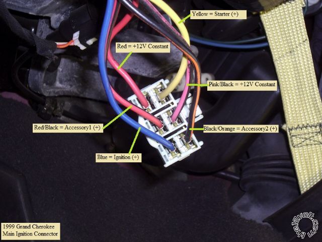
1. Purple Accessory Jeep RED / Black @ Ignition harness
2. Blue Ignition Jeep Blue @ Ignition harness
3. Red +12V Constant Jeep Red @ Ignition harness
4. RED / White +12V Constant Jeep Pink/Black @ Ignition harness
5. Yellow Starter Jeep Yellow @ Ignition harness
6. Green Ignition2/Accessory2 Jeep BLACK/ Orange @ Ignition harness *APS57-C Programmed for ACC
12 Pin Harness
1. White Parking Light In Jeep Chassis Ground w/ 1,300 Ohm resistor in-line
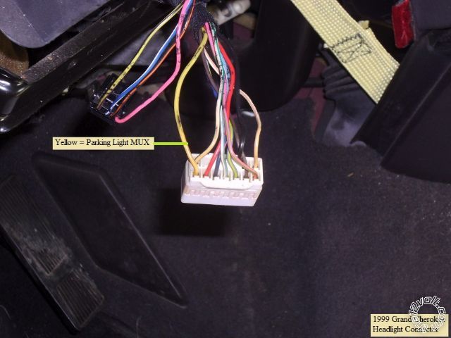
2. White Parking Light Out Jeep Yellow Parking Light MUX @ Headlight connector
3. BROWN / Black Brake Shutdown (+) N.A. Handled by D2D to bypass module
4. Brown (+) Inhibit Not Used
5. Empty Empty Empty
6. Gray Hood Pin (-) Jeep connect to kit supplied & installed Hood Pin
7. GREEN/ YELLOW Wait to Start / GlowPlug Not Used
8. Light Blue Ignition 3 (-) Not Used
9. Gray/Black (-) Inhibit Not Used
10. Black Chassis Ground Jeep Chassis Ground
11. GREEN/ Orange Tach (AC) N.A. Handled by D2D to bypass module **APS57-C programming required
12. Yellow/Black Alarm Ignition Output Not Used
Channel 3 White 2 Pin
Dark Blue Channel 3 Not Used
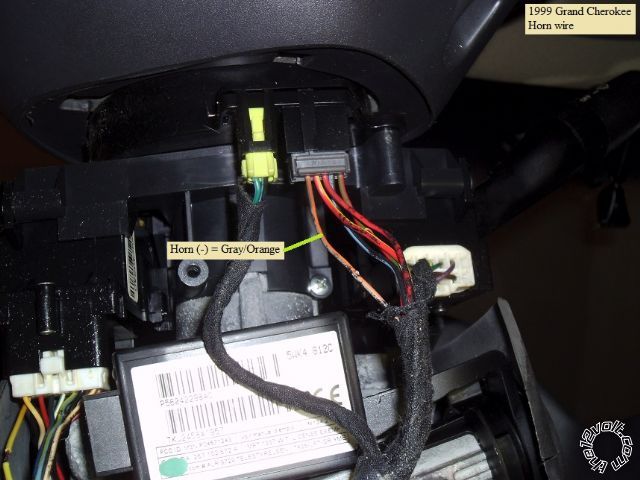
BLACK/ White Horn (-) Jeep Gray/Orange @ Steering Column connector
Door Lock Tan 2 Pin
Red (-) Lock and (+) Unlock N.A. Handled by D2D to bypass module
Green (-) Unlock and (+) Lock N.A. Handled by D2D to bypass module
AUX White 4 Pin
BLACK/ Blue Factory Disarm/Pulse before Start Not Used
BLACK/ Green Factory Arm/Pulse after Start Not Used
BLACK/ Red Pulse after shutdown Not Used
BLACK / YELLOW Pulse during Crank Not Used
Transponder Yellow 2 Pin
Red +12V constant Not Used
Black GWR (-) Status Output Not Used
D2D Tan 4 Pin Plug FLDL1 bypass module
Antenna Black 3 Pin Plug Antenna
White LED Plug Antenna
Blue Program Switch Antenna
Follow the FLDL1 w/DL CH6 firmware install guide for the 3 or 4 connections it has to the Jeep. Also,
be sure to set the bypass modules' Installation Mode to D2D ( one blink ) and lock it in. This is covered
in the install guide.
Disassembly :
Lower the tilt steering and remove the trim panel just below the instrument panel by pulling it straight away
from the dash.
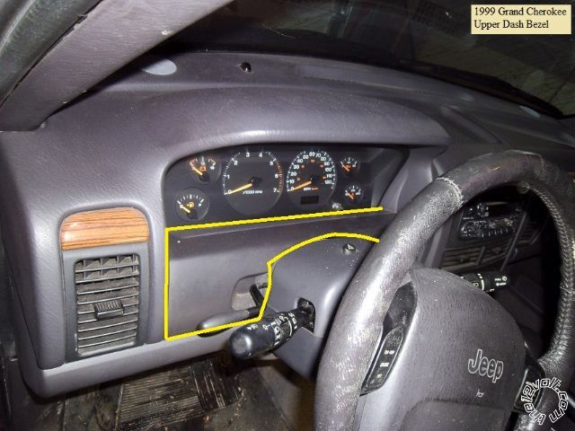
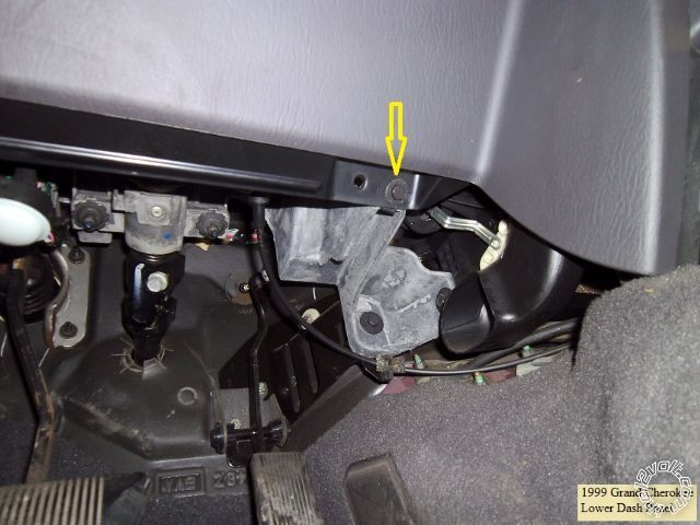
This will expose two Phillips screws ( one on each side of the steering column. These are the lower dash panel's
upper mounting fasteners.
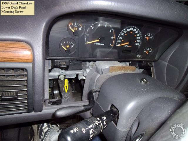
Remove them and then this Phillips screw on the side dash panel.
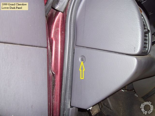
Finally, remove two 10mm screws from the bottom corners of the lower dash panel and pull the panel off.
Remove this Phillips screw at the bottom of the steering column cover and separate the cover halves.
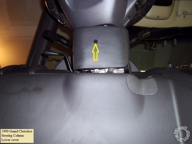
This will expose all the necessary wiring.
Wires :
This is a photo of the main Ignition connector, unplugged from the connector.
Here is a picture of the underside of the steering column with the connectors marked.
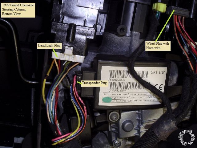
This is a close-up of the Headlight plug and the Parking Light MUX wire.
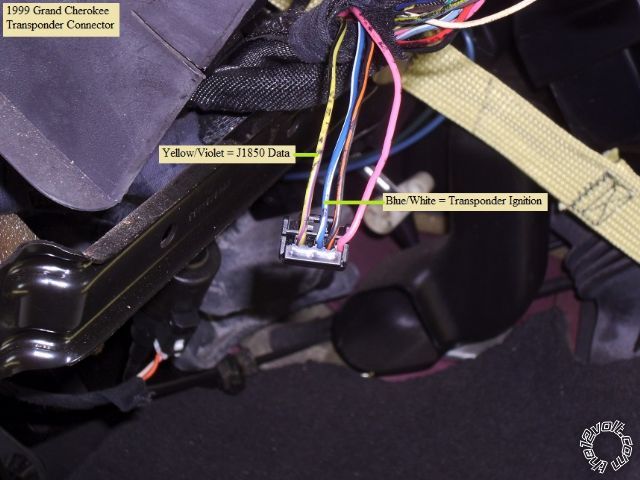
Next is a close-up of the transponder plug with the necessary wires marked.
Below is a close-up of the Horn wire.
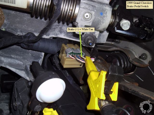
While not needed with the FlashLogic bypass modules, some bypass modules do not supply the
Brake signal ( EVO-ALL ), so here is a photo of the Brake wire :
Install Notes :
Here is a link to the Audiovox Prestige APS57-C Install guide :
https://www.the12volt.com/installbay/file.asp?ID=990
Here is a link to the FlashLogic WEB site : https://www.flashlogic.com/
Enter the Jeep G.C.'s info and download the FDDL1 ( or FLCAN ) install guide.
There is plenty of room under the dash for component placement and several good Chassis Ground bolts.
Firewall pass-through for the hood pin can be found at the hood release cable grommet.
This install was done using D2D Mode. This saves the installer from having to make 7 connections between
bypass module ( FLDL1 ) and the remote start unit ( ADS57-C ). There are two APS57-C programming changes
that must be made. First, to support DBI D2D Tach Mode, Bank 3, 5th Feature must be set to DBI Tach.
Additionally, Bank 3, 7th Feature must be changed to "Same as Accy" so the thick Green ignition wire will output
as required for the Jeep's Accessory2 circuit. The defaults will be OK for everything else.
Overall, this is a very easy vehicle to do. Only 14 or so wire connections to the vehicle ( including the hood pin
and Chassis Ground ). Plenty of room for harness access and soldering. Figure on a pleasant 4 hour install
for the average DIYer.
-------------
Soldering is fun!
Replies:
Posted By: metz35
Date Posted: October 25, 2014 at 6:57 PM