2009-2010 Ford Edge Remote Start Pictorial
Printed From: the12volt.comForum Name: Car Security and Convenience - Alarm/Remote Start Pictorials
Forum Discription: Installer submitted Alarm, Keyless Entry, and Remote Start Pictorials from our Car Security and Convenience forum.
URL: https://www.the12volt.com/installbay/forum_posts.asp?tid=138699
Printed Date: May 23, 2026 at 9:31 PM
Topic: 2009-2010 Ford Edge Remote Start Pictorial
Posted By: kreg357
Subject: 2009-2010 Ford Edge Remote Start Pictorial
Date Posted: March 21, 2015 at 5:05 PM
This is a Remote Start with Keyless Entry Pictorial on a 2010 Ford Edge. The 2009 model year is the same and its' sister vehicle, the
2009 - 2010 Lincoln MKZ, is also the same. This Pictorial will be useful for the 2007 - 2008 Edge models also.
The vehicle in this Pictorial had Ford's PATS3 transponder system, power locks and power lift gate. It did not have the Factory
Alarm or the factory installed hood pin. While there is a full featured bypass module available for this vehicle from Fortin that will
simplify the install, this Pictorial will use a less expensive bypass module and make direct connections to the necessary vehicle
wires. Additionally, this vehicle has "one-touch" starting and built in anti-grind. This allows a no-tach install and eliminates the
need for an anti-grind relay / circuit.
There are many quality R/S w/Keyless systems available to the DIY'er. I chose the Ultra Start U1272XR Pro system. Other units
worthy of your consideration are the Avital 4103, Comtustar CS800-s, Audiovox APS57E and the Viper 4105V. For the bypass
module I used the Directed XK05 flashed with the PKTI firmware. This firmware flash requires the XKLoader2 cable. Other bypass
modules more suited to DIY'ers are the Fortin Key-Override-ALL and EVO-KEY, the XpressKit PKALL and PKTX, and from iDatalink
the ADS TBSL KO. All of these modules come pre-flashed from the factory with the correct firmware for this install, saving the expense
of a flash cable. Remember that all of the bypass modules listed above will require two working, non-clone, ignition keys during module
to vehicle programming.
Here is the wiring :
U1272
6 Pin Ignition Harness
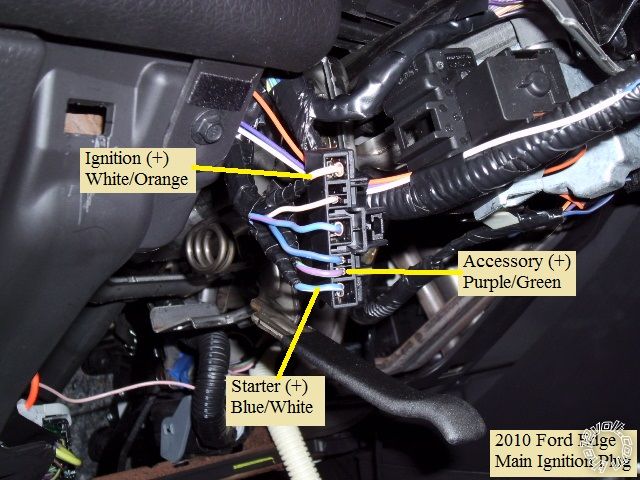
1 Yellow (+) Starter Output BLUE/WHITE (+) @ IGNITION Harness, (BLACK 7-Pin Plug) Pin 7
2 Green (+) Accessory Output PURPLE / GREEN (+) @ IGNITION Harness, (BLACK 7-Pin Plug) Pin 6
3 Red (+) +12V constant ---\ ______ RED (+) 100AMP @ SJB, (BLACK, 1-Pin Plug(G), Pin 1 ( fuse left at 30 Amps )
4 Red (+) +12V constant ---/ this wire was joined to the above wire between the fuse & the brain
5 White (+) Flex Relay Output not used
6 Blue (+) Ignition Output WHITE/ ORANGE (+) @ IGNITION Harness, (BLACK 7-Pin Plug) Pin 1
2 Pin Harness
Black (-) Main Chassis Ground Chassis Ground
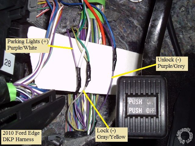
White Selectable Parking Light Output PURPLE / WHITE (+) in DRIVERS KICK PANEL * Set jumper to (+)
9 Pin Harness
1 Yellow (-) Rearm Output not used
2 Brown (-) Disarm Output not used
3 Black (-) AUX1 Output not used
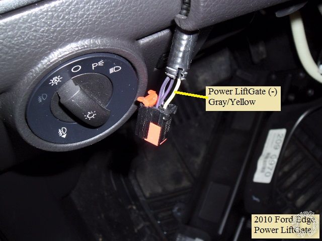
4 RED / White (-) Trunk Release GRAY / YELLOW (-) @ the Power Liftgate Switch
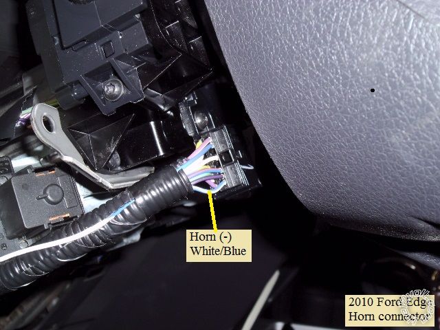
5 WHITE/ Blue (-) Horn Output BLUE/WHITE (-) @ HORN Switch **
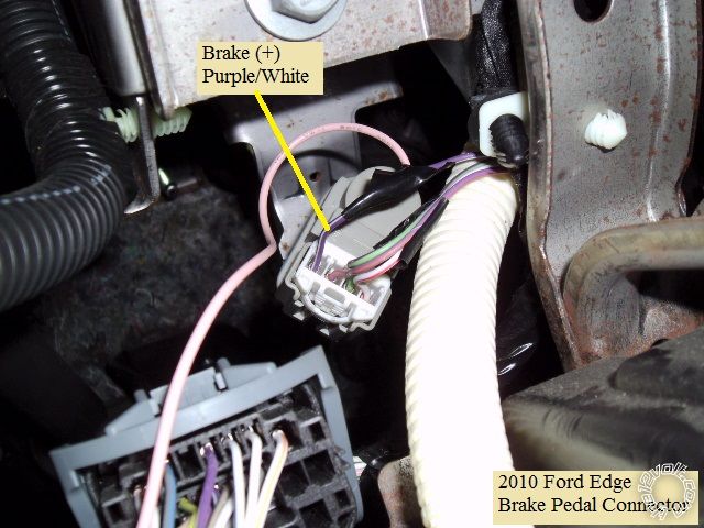
6 Pink (+) Brake Input PURPLE / WHITE (+) @ BRAKE Switch
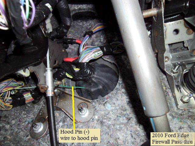
7 GREEN / WHITE (-) Hood Pin Input to kit supplied hood pin
8 Blue/White (AC) Tach Input not used
9 Blue (+/-) Glow Plug/WTS/Trigger Input not used
** While all the wiring guides listed the Horn wire as Blue/White, it sure looked WHITE/ Blue to me. There is a Blue/White wire in the
connector, so cautious testing with a DMM is necessary.
Lock Harness
Green (-) Lock GRAY / YELLOW (TYPE B) in DRIVERS KICK PANEL
Blue (-) Unlock PURPLE / GRAY (TYPE B) in DRIVERS KICK PANEL
3 Pin Bypass Harness
Red +12V to XK05 Red wire at Pin 9 of 10 Pin connector
Black Ground to XK05 Black wire at Pin 10 of 10 Pin connector
WHITE/ Violet (-) GWR to XK05 Brown wire at Pin 1 of 10 Pin connector
The only U1272 programming change from the factory defaults suggested is Mode 4, Setting 1 to Option 2 for Hybrid Mode 2.
This setting seems to work well on vehicles with no Starter wire and/or "one-touch" starting.
XK05 w/PKTI wiring
Pin 1 Brown wire to U1272 WHITE/ Violet ( listed above )
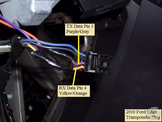
Pin 5 Violet wire ( RX) to Edge 4 Pin transponder plug, Pin 4, Yellow/Orange wire
Pin 8 Orange wire ( TX ) to Edge 4 Pin transponder plug, Pin 3, PURPLE / Gray wire
Pin 9 Red to U1272 Red ( listed above )
Pin 10 Black to U1272 Black ( listed above )
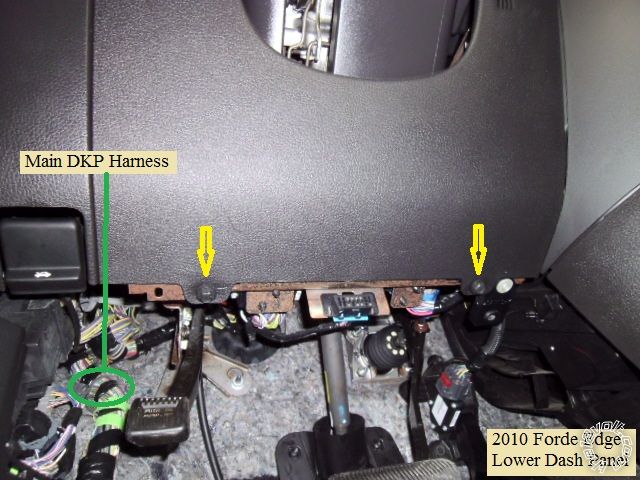
PURPLE / White and Gray / YELLOW seem to be a popular color for Ford. There are many wires this color in the thick harness in the DKP
so careful testing is required. If you don't want to search for these wires, you can find them at the SJB. Access to the SBJ without
dropping it or pulling the connectors is limited. This install was done with the battery connected and only the main ignition, liftgate
and transponder plugs disconnected during wire connection and soldering.
Disassembly :
Remove the two 10mm screws indicated and pull the lower dash panel straight back.
There are three screws holding the lower steering column cover in place. The machine screw closest to the engine is a Torx 25,
while the other two plain screws are Torx 20's. Separate the two halves at the side seams and remove the lower shell. The upper
shell / instrument bezel assy only needs to be removed if you have the power liftgate and wish to control that from the R/S FOB's.
There are two 7mm screws, one at each lower side, remove them and then pull the instrument bezel straight back.
That is all that needs to be removed for the install.
Wires :
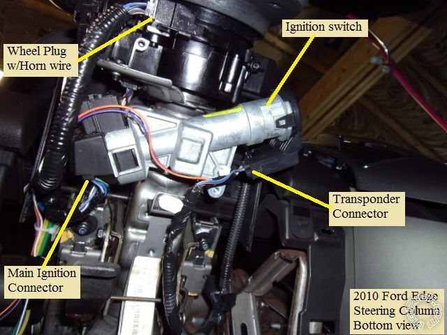
This is a bottom view photo of the steering column :
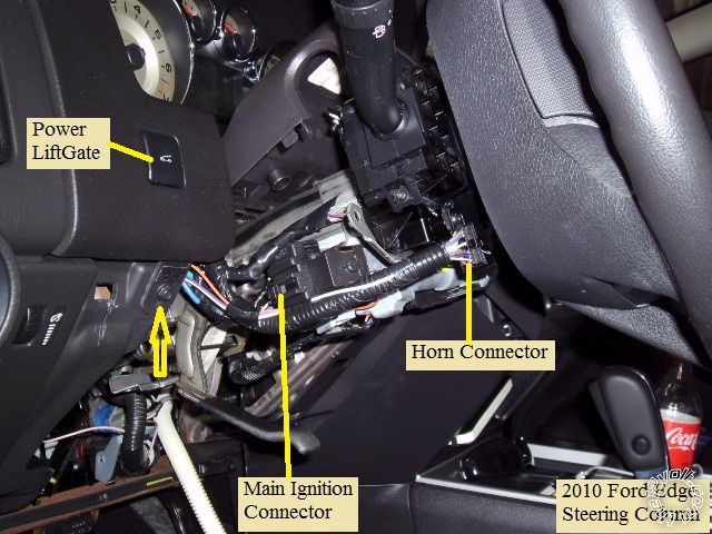
Here is a view of the left side of the steering column :
This is a photo of the main ignition connector ( unplugged ) with the wires marked :
Next is a photo of the transponder connector ( unplugged ) with the wires marked :
The horn wire is shown below :
The Brake wire can be found at the brake pedal switch, shown below :
As mentioned, getting to the SJB is difficult but the necessary wires can be easily found in this harness in the DKP :
After removing the instrument bezel, the Power Liftgate wire is found in this connector at the back of the switch :
The main wire harness grommet can be used as the firewall pass-through for the Hood Pin wire :
There is ample room under the dash for R/S module placement and many suitable Chassis Ground bolts available. Proper
allowances should be made ( with post-install testing ) for the wires going to the steering column due to its' tilt / telescopic function.
-------------
Soldering is fun!
Replies:
Posted By: redshirt
Date Posted: September 05, 2016 at 11:43 AM
I also wanted to locate the defrost trigger wire and I did except it doesn't turn the defrost button on, but who cares about that. That particular wire is on the blue connector behind the climate control panel and the wire color was "WHITE/ pink" (in my opinion). It is a latched negative 200ma requirement, of course please test with a DMM.
Others have also posted issues with the radio staying on after they turn the remote start off away from their car. While this is true, the radio turns itself off after 10 minutes, hopefully it doesn't kill anyone's battery.
Posted By: backshot
Date Posted: February 02, 2017 at 11:45 AM
Posted By: kreg357
Date Posted: February 04, 2017 at 11:00 AM
CN1
1 Red +12V Constant RED (+) 100AMP @ SJB, (BLACK, 1-Pin Plug(G), Pin 1 ( fuse left at 30 Amps )
2 GREEN / WHITE + Parking Light Out PURPLE / WHITE (+) in DRIVERS KICK PANEL
3 RED / White +12V Constant This wire was joined with the Pin 1 Red wire between the fuse & the brain + PKFM Red
4 White + Accessory PURPLE / GREEN (+) @ IGNITION Harness, (BLACK 7-Pin Plug) Pin 6
5 Blue + Selectablenot used
6 Yellow + Starter BLUE/WHITE (+) @ IGNITION Harness, (BLACK 7-Pin Plug) Pin 7
7 Green + Ignition WHITE/ ORANGE (+) @ IGNITION Harness, (BLACK 7-Pin Plug)
8 Black Chassis Ground Chassis Ground + PKFM Black
CN2
1 GREEN / WHITE (-) Parking Lights not used
2 RED / Black (-) Starter not used
3 WHITE/ Black (-) Accessory not used
4 Black (-) Statusto PKFM Brown
5 Orange (-) Rearm not used
6 ORANGE / White (-) Disarmnot used
7 White (-) Horn BLUE/WHITE (-) @ HORN Switch
8 Gray/Black (-) Hood Pin to kit supplied hood pin
9 Lt Blue/White (+) Brake PURPLE / WHITE (+) @ BRAKE Switch
10 RED / White (-) Trigger Start not used
11 Red (+) Trigger Start not used
12 Yellow/Black Tach not used
CN3
1 Empty
2 Violet/White (-) Trunk Release GRAY / YELLOW (-) @ the Power Liftgate Switch
3 ORANGE / Black (-) Driver Priority Unlock not used
4 Blue (-) Unlock PURPLE / GRAY (TYPE B) in DRIVERS KICK PANEL
5 Blue/Black (-) Lock GRAY / YELLOW (TYPE B) in DRIVERS KICK PANEL
6 Empty
No Tach connection is necessary. The vehicle has "one touch" starting and built in anti-grind. You can set the CS800-s
to Assumed Time Crank, Program Option 2-04 Setting 4.
I'm not a DEI PKFM user and there appear to be two flavors of firmware for your application, PKF3 and PKFORD. Ensure you
follow the install guide for the firmware flashed on to the module.
-------------
Soldering is fun!