2013-2015 Ram 1500 Remote Start Pictorial
Printed From: the12volt.comForum Name: Car Security and Convenience - Alarm/Remote Start Pictorials
Forum Discription: Installer submitted Alarm, Keyless Entry, and Remote Start Pictorials from our Car Security and Convenience forum.
URL: https://www.the12volt.com/installbay/forum_posts.asp?tid=138747
Printed Date: April 30, 2026 at 12:51 PM
Topic: 2013-2015 Ram 1500 Remote Start Pictorial
Posted By: kreg357
Subject: 2013-2015 Ram 1500 Remote Start Pictorial
Date Posted: March 30, 2015 at 8:44 PM
This is a Pictorial on the 2013 - 2015 Dodge RAM 1500 TIP key ( non-PTS ) for a basic remote start w/keyless entry install. This
truck did not have the Factory Alarm. This is an advanced DIY project due to the additional "tools" needed.
This install is very easy but it does require addition tools ( Fortin Flashlink2 cable ). For a "No-Key-Required" install, all the major
bypass manufacturers use a key cloning process that requires their bypass module flash cable and in the case of XpressKit and
iDatalink, authorized dealer access to perform the extended bypass module programming. This install is possible for the DIYer
that is willing to spend the extra money on the necessary module flash cable.
For this install a Compustar CS800-s and an EVO-ALL was selected. There are many other quality remote starter choices available
to the DIYer that are reasonably priced and capable of handling the vehicle / install needs.
Follow the Fortin Install Guide very closely. The CS800-s is capable of going in D2D mode with an iDatalink module. With the
EVO-ALL, I connected the two modules in W2W mode on the bench prior to install. As shown in the install guide, you will need
a 1N4001 diode, a 1,000 ohm resistor and ( not shown ) a 7.5 Amp fuse.
Here is a photo of the CS800-s and EVO-ALL bench prepped in W2W mode ( almost complete ) :
Disassembly :
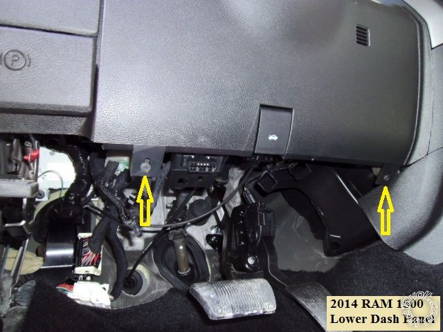
Remove the drives side dash access panel with a non-marring trim tool. Remove the driver side door sill and kick panel trim piece
by lifting the rear edge first and then continue lifting to the DKP. Next pull the panel straight back. Remove the two 7mm screws
shown below and pull the lower dash panel straight away from the dash.
Wires :
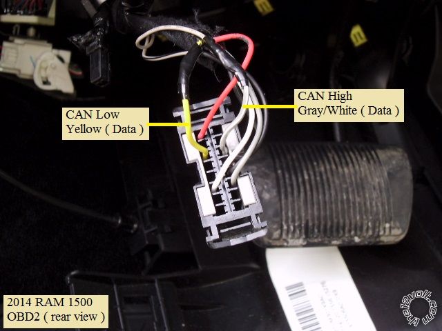
Here is a photo of the OBD2 plug ( removed from the lower dash panel ) with the CAN wires marked :
This is a photo of the Trailer prep connector found under the dash, behind the ignition switch assy, with the Ignition wire marked :
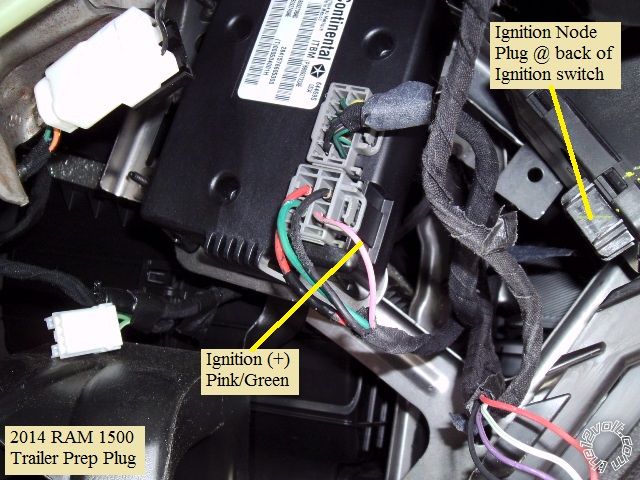
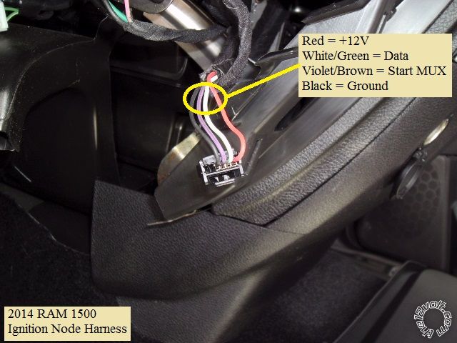
Next is a picture of the main ignition harness ( unplugged from the back of the TIP ignition switch assy shown above ) :
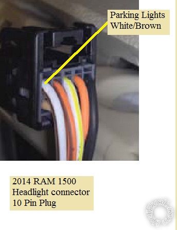
The Parking Light wire is found at the Headlight connector. You might have to remove the headlight / vent assy to get at this plug :
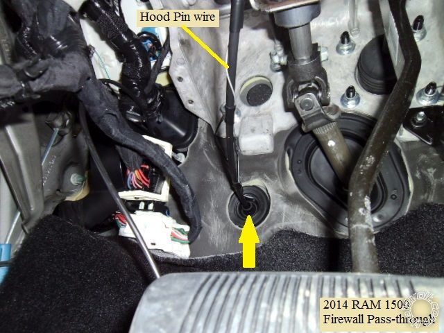
For the Hood Pin wire, this convenient firewall grommet was used :
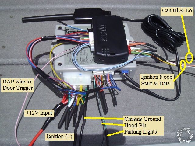
Here is the wiring when using a CM800-s and EVO-ALL flashed with 74.19 firmware ( W2W mode ) :
CM800-s
CN1
1 Red +12V Constant Combined with CN1-3, fused down to 7.5 Amps & connected to -->
2 GREEN / WHITE + Parking Light Out not used
3 RED / White +12V Constant --> the Ignition Node Connector RED / Green @ Pin 1
4 White + Accessory not used
5 Blue + Selectable not used
6 Yellow + Starter EVO-ALL RED / Blue @ A9
7 Green + Ignition with 1N4001 RAM 1500 Pink/Lt Green @ Trailer Prep connector & EVO-ALL Yellow @ A1 *
8 Black Chassis Ground Chassis Ground ( with EVO-ALL Black B3 )
* Follow the EVO-ALL install diagram exactly for this wire and diode.
CN2
1 GREEN / WHITE (-) Parking Lights through 1k resistor to RAM 1500 WHITE/ Brown @ Headlight plug
2 RED / Black (-) Starter not used
3 WHITE/ Black (-) Accessory not used
4 Black (-) Status EVO-ALL Dark Blue @ A8
5 Orange (-) Rearm not used
6 ORANGE / White (-) Disarm not used
7 White (-) Horn not used
8 Gray/Black (-) Hood Pin to kit supplied hood pin
9 Lt Blue/White (+) Brake EVO-ALL Black @ A11
10 RED / White (-) Trigger Start not used
11 Red (+) Trigger Start not used
12 Yellow/Black Tach EVO-ALL Pink @ A12
CN3
1 Empty
2 Violet/White (-) Trunk Release not used
3 ORANGE / Black (-) Driver Priority Unlock not used
4 Blue (-) Unlock EVO-ALL PURPLE / White @ A3
5 Blue/Black (-) Lock EVO-ALL Purple @ A2
6 Empty
EVO-ALL connections not listed above :
EVO-ALL Red @ B4 to CS800-s CN1-1 Red
EVO-ALL Black @ B3 to CS800-s CN1-8 Black
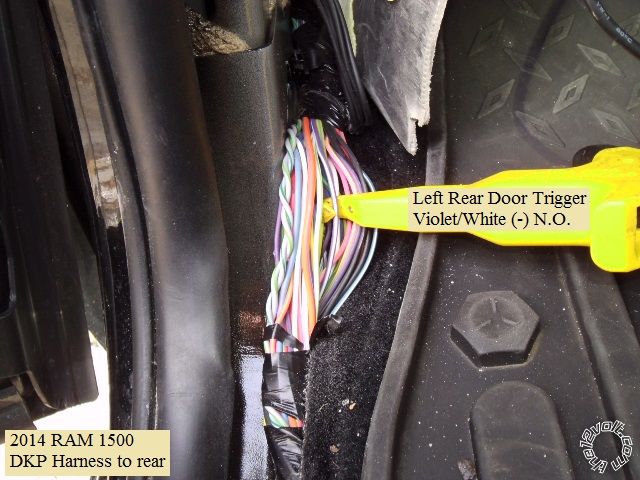
EVO-ALL Pink/Black @ A15 to RAM 1500 Violet/White in DPK **
EVO-ALL Lt Blue/Black @ A10 + WHITE/ Green @ D4 to RAM 1500 body side of cut WHITE/ Green Data wire @ Ign Node Plug
EVO-ALL WHITE/ Red @ D6 to RAM 1500 plug side of cut WHITE/ Green Data wire @ Ign Node Plug
EVO-ALL Lt Blue @ A20 + YELLOW /GREEN @ D1 to RAM 1500 body side of cut PURPLE / Blue Start wire *** @ Ign Node Plug
EVO-ALL Yellow/Red @ D3 to RAM 1500 plug side of cut PURPLE / Blue Start wire *** @ Ign Node Plug
** This wire is shown in the install diagram as connected to the Violet Driver Front Door Pin wire at the BCM. I chose to go to
the Violet/White Rear Door Pin wire in the DKP for easier access.
*** This wire is listed as PURPLE / Blue by Fortin but appears to be PURPLE / Brown. It is listed as PURPLE / Brown by XpressKit and iDatalink.
Notes :
There is plenty of room for module placement under the dash.
The EVO-ALL allows key take-over without a 45 second time limit but the trucks door(s) must be unlocked with the after-market FOB
or the engine will shutdown as soon as the Brake pedal is pressed .
The factory FOB that was used for bypass module programming will not Lock or Unlock during remote start engine run time. The
other factory FOB will but if used to unlock the truck during remote start engine run time for key-take-over, the engine will shut down
as soon as the brake pedal is depressed ( no key take-over ).
The truck has "one-touch" starting, so programming the CS800-s to Tach Mode or Fixed 3 second crank output is OK.
-------------
Soldering is fun!
Replies:
Posted By: racerjames76
Date Posted: April 04, 2015 at 12:22 PM
Good write up!
When doing a remote starter using a standard starter with bypass in vehicles like this it becomes painfully obvious that the remote starter is doing nothing but handle the antenna/remote control aspects.
We use a DBALL2 in RSR mode and these trucks are done in 20 minutes.
I will give ya grief about drawing power for the big remote start brain from the ignition 12v source. This is typically a low amp current supply, and at least with directed and Audiovox systems the onboard relays can sometimes draw more than that little wire can handle.
An RSR install should be fine, but drawing power for the big brain units may result in a popped fuse and a stranded vehicle.
I would suggest that if doing it the "old fashioned way" like this to use the 12v supply at the trailer plug or find another larger non critical 12v source.
-------------
To master and control electricity is perfection. *evil laugh*
Posted By: kreg357
Date Posted: April 04, 2015 at 8:22 PM
Excellent point on the +12V power! The DB-ALL2 RSR is very quick but due to the required dealer access for the Key-2-Go
programming, not really suited for the DIY'er, hence the Fortin EVO-ALL.
I tend to agree with you on the +12V source. Both iDatalink and Fortin show diagrams with the connection at the TIP ignition
connector, and neither with any type of fuse protection shown. Perhaps even scarier was the DB-ALL2 RSR getting power from
the OBD2 connector. As you mentioned, there are alternative places to obtain the +12V low current draw power for this install.
The +12V wire at the Trailer Prep plug is very convenient. Going to the BCM, Connector B, Pin 3 Red wire is another option inside
the cab.
I did the Pictorial following the Fortin EVO-ALL install guide pretty closely, only making a few minor changes ( the added fuse and
the Door Pin wire for the RAP connection ). Overall, using a R/S w/Keyless entry system like the CS800-s as the remotes interface
should not draw too much current ( no alarm functions or siren and (-) Parking Lights ). So far, none of these trucks have come
back or had any issues, but I believe future installs will go with a safer power source, regardless of the bypass manufacturer's
install diagram's. 
-------------
Soldering is fun!
Posted By: racerjames76
Date Posted: April 04, 2015 at 10:27 PM
Ah that is a discussion for another thread


-------------
To master and control electricity is perfection. *evil laugh*
Posted By: kreg357
Date Posted: April 14, 2015 at 6:33 PM
Just noticed that I omitted the picture of the Door Pin wire for the EV-ALL's RAP connection.
Here is a photo of the Drivers Rear Door Trigger wire found in the DKP harness :
-------------
Soldering is fun!
Posted By: bigcyphe
Date Posted: July 05, 2015 at 2:41 AM
-------------
You learn something new everyday. Whether or not you fail to file it as useful is up to you.
Posted By: kreg357
Date Posted: July 05, 2015 at 3:55 AM
I'm still "old-school" with W2W, solder and heat shrink tube. It's so much easier to do the prep on the bench. Easy access, good lighting, tools at hand with a solder station, etc. All that is left is finding a good location in the vehicle and neatly running the wires to their connection points.-------------
Soldering is fun!
Posted By: bigcyphe
Date Posted: August 07, 2015 at 2:02 AM
-------------
You learn something new everyday. Whether or not you fail to file it as useful is up to you.
Posted By: kreg357
Date Posted: August 07, 2015 at 11:22 AM
-------------
Soldering is fun!
Posted By: dodgeman21
Date Posted: March 24, 2017 at 4:17 AM
I have a 2014 RAM 1500 installed a Autopage 730 alarm
I have found the purple wire driver door and purple /white pass door
I have diode isolated them both and hooked them to the negative door trigger of the alarm.
When I arm the alarm I get a error code on my remote to check the doors that one is open.
I took a test light and hooked it to the - door wire trigger and +12v the other end.
with the door open the test light is bright when I shut the door the test light goes dim but still lit.
This is telling my alarm my door is open but yet my truck says its closed.
One would think theres some kind of short.
When I unplug the 24 pin plug from the BCM the light is bright with door open and off when door is closed.
So why does it stay dim when the plug is plugged into the BCM with the door closed?
Any help would be thankful
Posted By: kreg357
Date Posted: March 28, 2017 at 7:15 AM
info on all the door pins and the hood pin for that truck :
Driver's Front Door Pin VIOLET (-) BCM WHITE 48 PIN CONN, PIN 9
Pass Front Door Pin VIOLET/WHITE (-) BCM WHITE 48 PIN CONN, PIN 23
Driver's Rear Door Pin VIOLET/GREY (-) BCM BLUE 24 PIN CONN, PIN 18
Pass Rear Door Pin VIOLET/YELLOW (-) BCM BLACK 48 PIN CONN, PIN 5
OEM Hood Pin VIOLET/LT BLUE (-) BCM BLACK 24 PIN CONN, PIN 11 * If factory equipped only.
If you were using a bypass module, most of the full feature models will supply the door status signal. That being
said, perhaps using the Dome Light signal would be a suitable alternative. Here is that info :
Dome Light YELLOW/VIOLET (+) BCM BLUE 24 PIN CONN, PIN 14
Note that this is a (+) signal. I'm not familiar with your Autopage 730 system, but is should have a (+) Door trigger
input.
-------------
Soldering is fun!