2015 Toyota Sienna H Key Remote Starter Install
While somewhat similar to the 2011 through 2014 models, the 2015 Sienna comes with the new high encryption H key.
Recently, the major bypass manufacturers released a data bypass module for these vehicles. This Pictorial will provide
a guide for a standard remote starter install using the ADS iDatalink offering.
Like most all Toyota vehicles, the factory Remote Keyless Entry system is disabled while the engine is running. Using
a remote start system that includes RKE is a good choice, especially with power sliding doors.
This install was on a Sienna LE. These do not come with the Factory Alarm system. There will be no factory hood pin
( and no bypass module supplied Hood Pin signal ). The kit supplied hood pin should be installed.
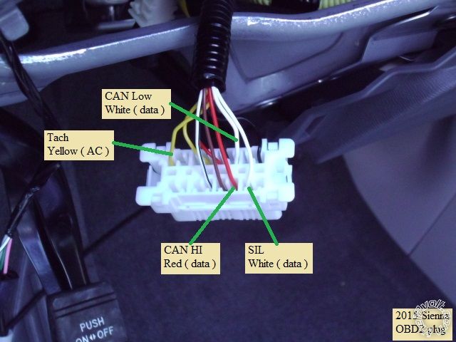
This engine does not have "one touch" starting so running in Tach Mode is a good idea. The bypass supplies a Tach
signal or your can go to the Tach wire shown at the OBD2 plug.
This engine does not have built in Anti-Grind. Adding the relay with anti-grind is a nice feature.
Disassembly :
Lift the driver side door sill trim and pull up and off. Remove the driver kick panel by removing the plastic retainer
and pull the panel straight back. Remove the driver side dash panel to allow access for the antenna harness routing
up the door pillar to the windshield.
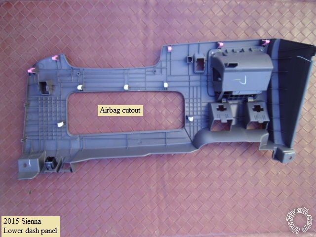
Remove the two 10mm bolts at the lower corners of the lower dash panel, then pull the panel straight back. There
are 5 retainer clips along the top edge. See photo below of back-side of lower dash panel.
Remove the two Phillips screws at the 10 and 2 o'clock positions exposed by turning the steering wheel.
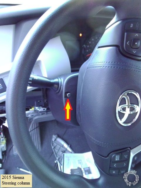
Press in at the side seams to separate the upper and lower steering column covers and remove the lower cover.
Wiring :
Follow the iDatalink ADS AL-CA with DL TL9 install guide. Also reference the Fortin EVO-ALL guide.
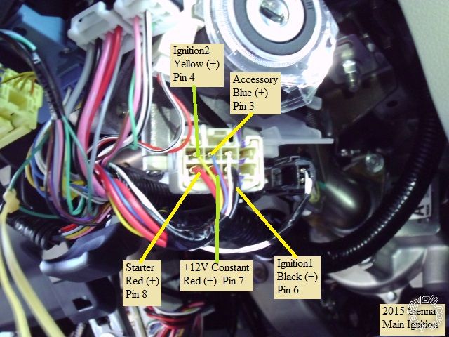
This is a photo of the main ignition wires. Note that there is a mixture of thick and thin wires at the plug. During bench
prep you could replace the thick Ignition2 and Accessory wires with thinner gauge wires to make install easier.
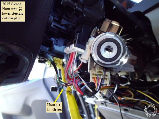
This is a photo of the Horn wire found in the steering column at the clock spring plug.
Next is the OBD2 connector :
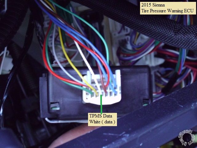
In the exposed dash, to the left of the steering column, is the Body ECU and the Tire Pressure Warning ECU :
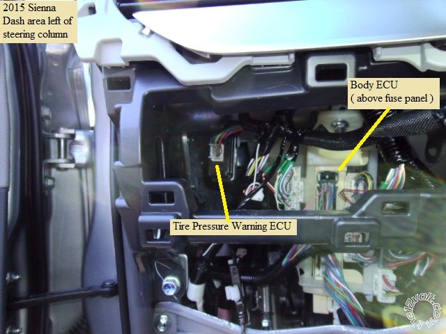
Here are the important wires in the Body ECU :
The hard to locate TPMS wire is in this Tire Pressure Warning ECU connector. Use a deep 10mm socket with a long
extension to remove the mounting bracket nut and pull the TPW ECU towards you.
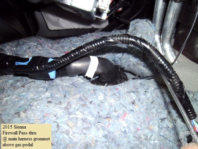
Firewall pass through for the hood pin wire can be found at the main engine harness grommet, pictured below :
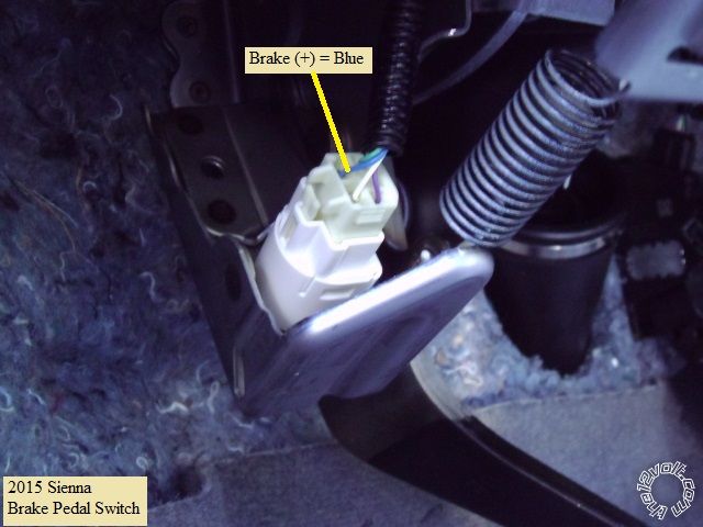
Bonus wires :
While not needed ( provided by the bypass module ), here is a photo of the brake wire :
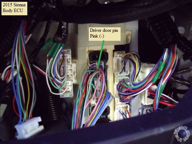
If your Sienna has Auto Headlights, be forewarned that with a certain sequence of events the battery can be inadvertently
drained. If the van was parked with the headlight switch in the Auto position and the van was remote started at night and
then remotely shutdown, the headlights would remain on until the battery was drained. Connecting the R/S (-) Rearm
output wire to the driver door pin would make the van think a door was opened after the engine was turned off and
the headlights would be turned off after 30 seconds. Here is a picture of the Drivers Door Pin wire at the Body ECU :
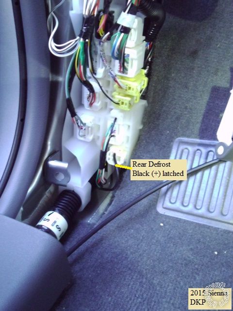
If your R/S system has the capability, here is a shot of the rear defroster wire in the bottom plug in the DKP. It needs
a high current (+) signal.
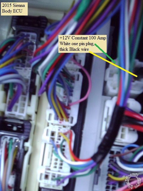
A good +12V power source for the defroster can be found at the upper right side of the Body ECU, shown below :
Notes :
The iDatalink bypass module can control the door locks while the engine is running. It also provides the built in Toyota
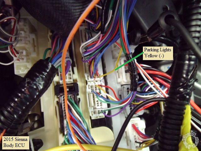
tone and flashes the Parking Lights while the engine is off.
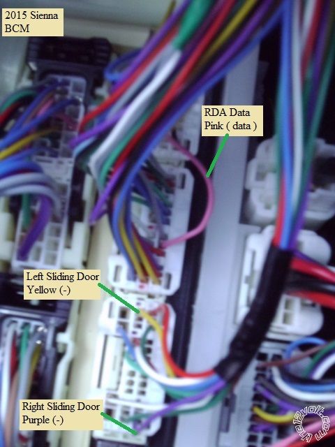
As noted in the install guide, the bypass module can only operate the sliding doors when the engine is off. If you want
sliding door operation at all times, use the Body ECU wires shown above ( and don't make those R/S connections to the
bypass module ).
There are many good locations for the Chassis Ground wire and R/S module placement. Make allowances in the R/S
harness / wires going to the steering column for its' tilt / telescopic movements. Test all wires with a Digital Multi Meter
before making quality solder connections.
-------------
Soldering is fun!
Great write up as always kreg. I need to start taking pictures again. I just did a 2015 Toyota Camry using an alca with the TL9 worked great.
Good tip on the auto lights. I had to pulse the door pin as well. I used a compstar 7200 module and had to relay the door pin. The rearm wasn't strong enough to pulse it.
-------------
If i Can't Install it I Don't need it Joe
chev104275 wrote:
Great write up as always kreg. I need to start taking pictures again. I just did a 2015 Toyota Camry using an alca with the TL9 worked great.
Good tip on the auto lights. I had to pulse the door pin as well. I used a compstar 7200 module and had to relay the door pin. The rearm wasn't strong enough to pulse it.
Did that require a SPDT relay? And if so, what connection on the relay did you need to make? Thnx
Just a regular SPST relay will do but it seems that the SPDT relay is more common and available. Here is the wiring for a SPDT relay
to provide a solid (-) signal to the door pin :
Relay Pin 86 to +12V constant ( fuse @ 2 Amps )
Relay Pin 85 to R/S (-) Rearm Output
Relay Pin 30 to Chassis Ground
Relay Pin 87 to Sienna Pink (-) Driver Door Pin
Relay Pin 87a not used
For these applications, I use a mini 12V DC SPDT relay that is rated at 10 Amps. They are available on EBay for ~ $1.
-------------
Soldering is fun!
kreg357 wrote:
Just a regular SPST relay will do but it seems that the SPDT relay is more common and available. Here is the wiring for a SPDT relay
to provide a solid (-) signal to the door pin :
Relay Pin 86 to +12V constant ( fuse @ 2 Amps )
Relay Pin 85 to R/S (-) Rearm Output
Relay Pin 30 to Chassis Ground
Relay Pin 87 to Sienna Pink (-) Driver Door Pin
Relay Pin 87a not used
For these applications, I use a mini 12V DC SPDT relay that is rated at 10 Amps. They are available on EBay for ~ $1.
Thnx for the info sir. What other some other example applications where you use a SPDT 10A relay for out of curiosity?
Basically any circuit that does not need more than 10 Amps. I use them for the (-) to (+) conversion when installing on certain GM
vehicles that have (+) Door Locks because they are less expensive and take up less space than a 451M module. They are useful on the
newer vehicles with extra low current ignition circuits ( ACC2, IGN2, and Starter Kill, etc ). Here is a link to a RAV4 Pictorial
where these mini-relays were used : https://www.the12volt.com/installbay/forum_posts.asp?tid=134111 The photos show them and then
shown again in the bench prepped R/S assembly. I get them in larger lots so the price is around $.50 each. They do take a little
more prep to solder on wires and insulate with heat shrink tube but they are very reliable and compact.
-------------
Soldering is fun!