2009-2012 Nissan Altima Remote Start Pictorial
Printed From: the12volt.comForum Name: Car Security and Convenience - Alarm/Remote Start Pictorials
Forum Discription: Installer submitted Alarm, Keyless Entry, and Remote Start Pictorials from our Car Security and Convenience forum.
URL: https://www.the12volt.com/installbay/forum_posts.asp?tid=140691
Printed Date: May 02, 2026 at 10:05 AM
Topic: 2009-2012 Nissan Altima Remote Start Pictorial
Posted By: kreg357
Subject: 2009-2012 Nissan Altima Remote Start Pictorial
Date Posted: January 19, 2016 at 8:07 PM
This is a Pictorial on a remote start with keyless entry on a 2010 Nissan Altima. The vehicle was a 4 door Sedan with the
4 Cylinder engine, CVT transmission, Factory Alarm and Push-to-Start. As such, this Pictorial will be applicable to similar
models in the 2009 through 2012 range.
Please note that there is another excellent Pictorial on the same vehicle. Here is a link to that Pictorial :
https://www.the12volt.com/installbay/forum_posts.asp?tid=129706
Since that post there have been some changes and updates to the firmware on the available bypass modules. This
Pictorial uses the current offering from iDatalink that simplifies the install greatly. There are some notable operational
differences that will be mentioned later. The nice part is that there is no need to pull the instrument cluster to access the
BCM. Only 11 vehicle wires are used for this install, plus a Chassis Ground connection.
For this install a Viper 4105V and an iDatalink ADS AL-CA flashed with the DL NI5 firmware was used. Being old school,
I connected the Viper and the ADS AL-CA in the W2W method. Slightly more prep work but very reliable results. The
Viper 4105V was chosen due to its' programming options, specifically Engine Checking = OFF and Cranking Time = 4
seconds. The long crank time ( Starter Output ) is required by this vehicle due to PTS and transponder challenge
sequence.
Disassembly :
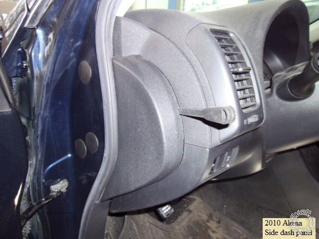
Remove the side dash panel using non-marring trim tools, as shown below :
Remove the lower dash fuse box access cover to expose the lone panel retention screw. Photo below :
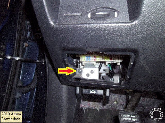
Remove the indicated screw and then pull the lower dash panel straight back and away. There are several plastic clips
along the top and side. Remove the Keyport assy and Traction Control switches from the panel and set the panel aside.
Remove the driver door sill and driver kick panel trim to expose the needed wire bundle and chassis ground point.
Wires :
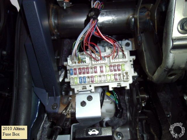
This is a photo of the drivers fuse box :
Here is a close up of the needed wires in the center plug :
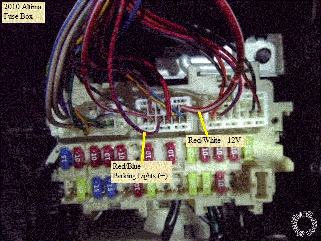
The +12V wire shown can handle the Viper and ADS AL-CA current needs and should be fused at 20 Amps or less.
This is the driver door sill harness :
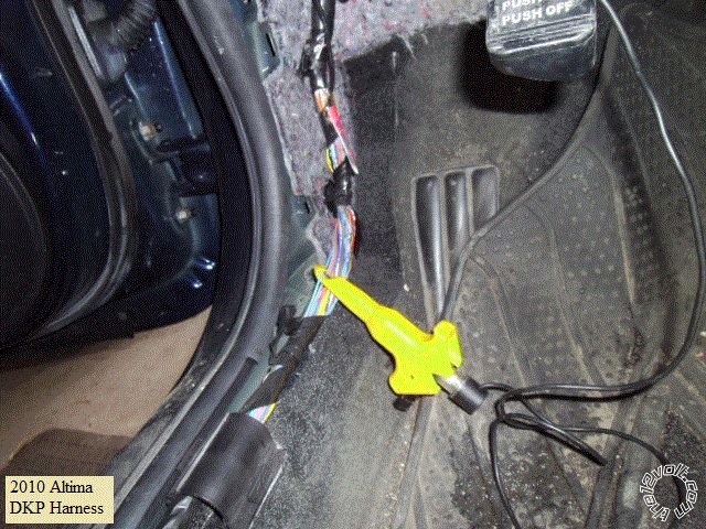
Also, low in the drivers kick panel is a factory ground point that can be used as Chassis Ground for the R/S system
Remember to use a soldered on terminal ring in the appropriate size for best results.
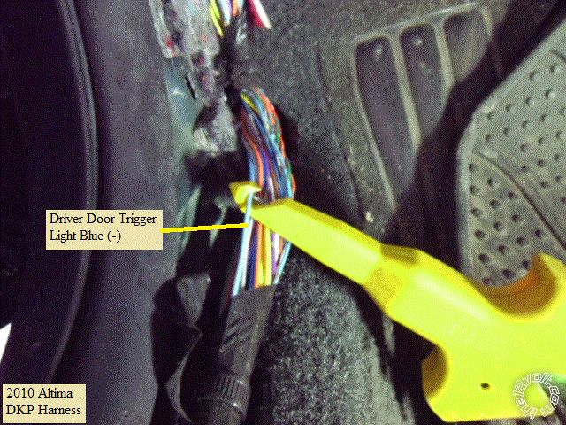
Here is a close up of the Driver Door Trigger wire :
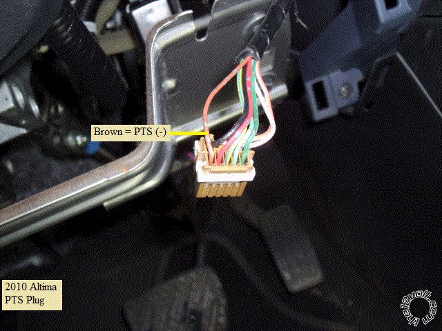
Reach up behind the PTS button and unplug the PTS connector. This is a photo of the PTS (-) wire :
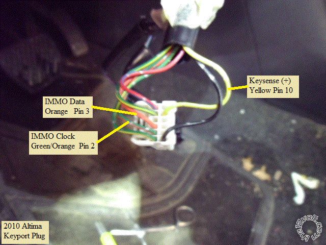
On the removed lower dash panel is the Keyport and the Keyport connector. Here is a picture of the 3 needed wires :
Next is a shot of the Brake (+) wire at the switch at the top of the brake pedal :
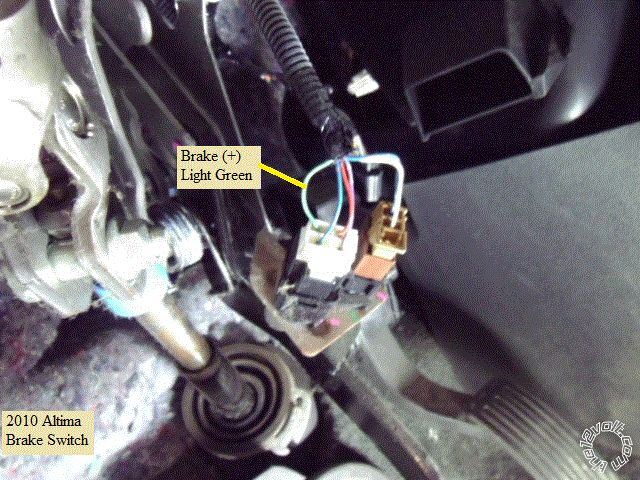
Follow the iDatalink install wiring diagram for this wire. Only the R/S Starter1 wire is connected. The R/S's Brake Input
must come from the bypass modules Brake Output, not directly from this vehicle wire.
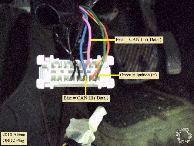
This is a photo of the OBD2 plug, also found on the removed lower dash panel :
Notes :
While the Viper 4105 was chosen due to its' programmable fixed long crank time, it does have a minor short fall. The Flex
Ignition output ( thick Pink/White wire ) can only be programmed for IGN2 or ACC2, not the needed (+) Starter2. Starter1
output goes to the Brake wire and a separate Starter2 goes to the ADS AL-CA. A polarity conversion mini-relay was used
to produce this Starter2 (+) signal controlled by the Vipers (-) 200mA Starter output.
Verify that the Altima has a Factory Hood Pin. If it does not have this hood pin, the bypass module will not be able to supply
the Hood Pin signal to the Viper and the Viper kit supplied hood pin should be installed and used.
As mentioned above, this install does not have any connections to the cars BCM. It handles most everything through data.
With no Arm and Disarm wires going to the BCM, the bypass module disarms the factory alarm by pulsing the ignition and
immobilizer prior to unlock and remote start. You will see the instrument cluster gauges light up briefly. This system has
no ability to arm the factory alarm system. As such, a lock command from the viper remotes will only lock the doors and
will not set the alarm. Make sure the customer is aware of this and that to set the alarm, the car must be locked with the
inside door button, the key in the door cylinder or the factory FOB.
If you wish to go D2D communications between the Viper and the iDatalink bypass module, obtain a FLCAN module or
flash the ADS AL-CA with the DBI version of firmware.
-------------
Soldering is fun!