2011-2014 Ford F-150 Remote Start Pictorial
Printed From: the12volt.comForum Name: Car Security and Convenience - Alarm/Remote Start Pictorials
Forum Discription: Installer submitted Alarm, Keyless Entry, and Remote Start Pictorials from our Car Security and Convenience forum.
URL: https://www.the12volt.com/installbay/forum_posts.asp?tid=143684
Printed Date: April 22, 2026 at 7:57 AM
Topic: 2011-2014 Ford F-150 Remote Start Pictorial
Posted By: kreg357
Subject: 2011-2014 Ford F-150 Remote Start Pictorial
Date Posted: October 28, 2017 at 5:56 AM
This is a quick and basic Pictorial on a 2014 Ford F150. This truck was an XLT with a V8, automatic
transmission, Factory Remote Keyless Entry and Factory Alarm. Similar 2011 through 2014 models
should be the same.
Notes on this truck :
The Factory Remote Keyless Entry continues to function during remote start run time.
The ECM controls engine start up ( "one-touch starting"). No Tach signal needed. Fixed crank time OK.
Engine has built-in Anti-Grind.
Remote Keyless Entry is part of the keys.
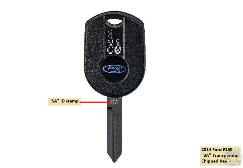
Considering this trucks features, it was decided to use a one button remote start system with compact
remotes. This will simplify the install. An Avital 4113 and a PKTX bypass module was chosen. Note
that these trucks have the SA key and could be either a 40 bit or an 80 bit transponder systems. The
PKTX install guide should be used to determine which transponder system is in use and which
programming steps should be followed to program the bypass module. You will need two working
non-clone keys to successfully program the bypass module. Factory SA key shown below :
Please note that there are many quality remote starter systems and bypass modules that will handle
these trucks. Other choices include the Ultra Start U1172, Compustar CS801-s and the Prestige
APS901E. Bypass modules for DIYers include the Fortin EVO-Key and the PKTX as these bypass
modules come from the factory with the correct firmware preloaded.
These photos were taken during system de-install. Install was done 3 years ago at lease inception.
Disassembly :
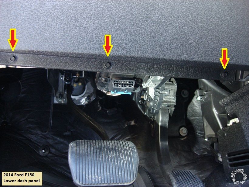
Remove the lower dash panel by removing the three 7mm screws at the bottom edge of the panel
as shown in the photo below, then pull the panel straight away at the top edge ( clips at each upper
corner ).
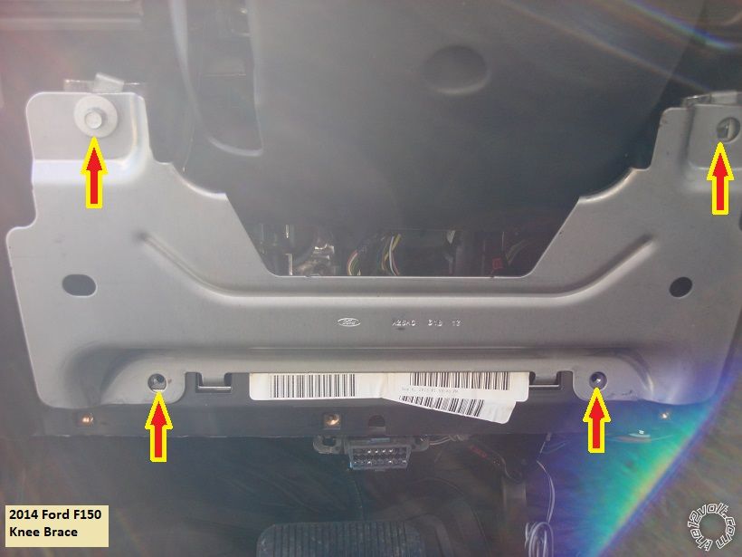
The knee brace is now exposed and can be removed by removing the four 8mm screws indicated in
the photo below.
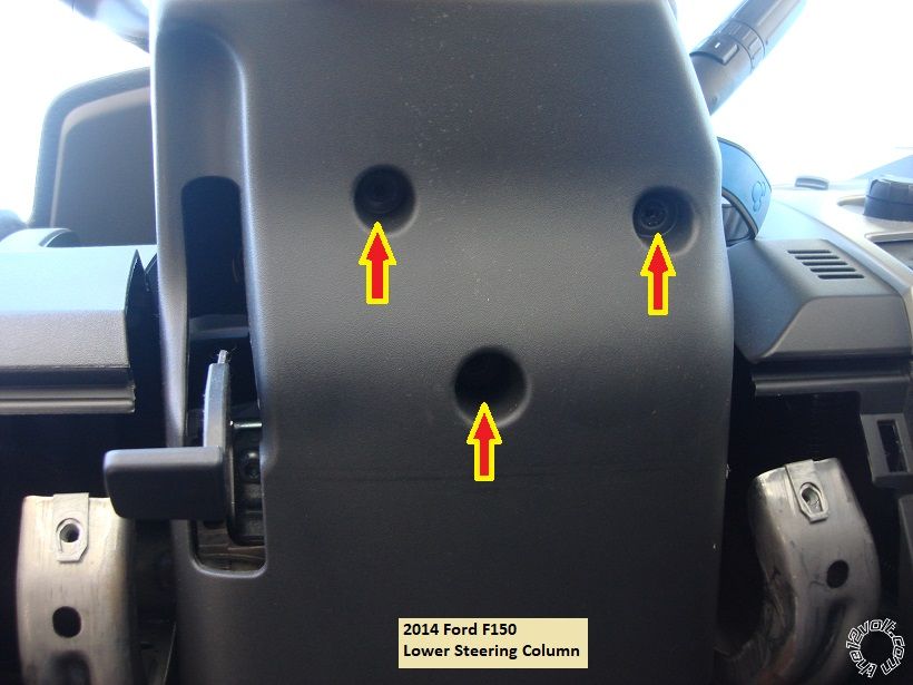
Next remove the lower steering column cover by removing the three 5.5mm screws shown in the next
photo and then separate the two halves :
Remove the passenger kick panel cover. Next lift the passenger door sill at the front edge then remove
the PKP by pulling it straight back. This will expose the necessary wires found at the BCM. No photos
of this available.
Wires :
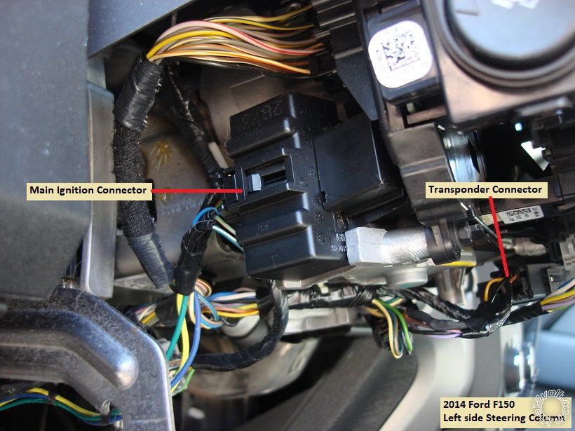
The ignition wires and the transponder wires are found in the steering column. Here is a photo of the
left side of the steering column with the two connectors marked :
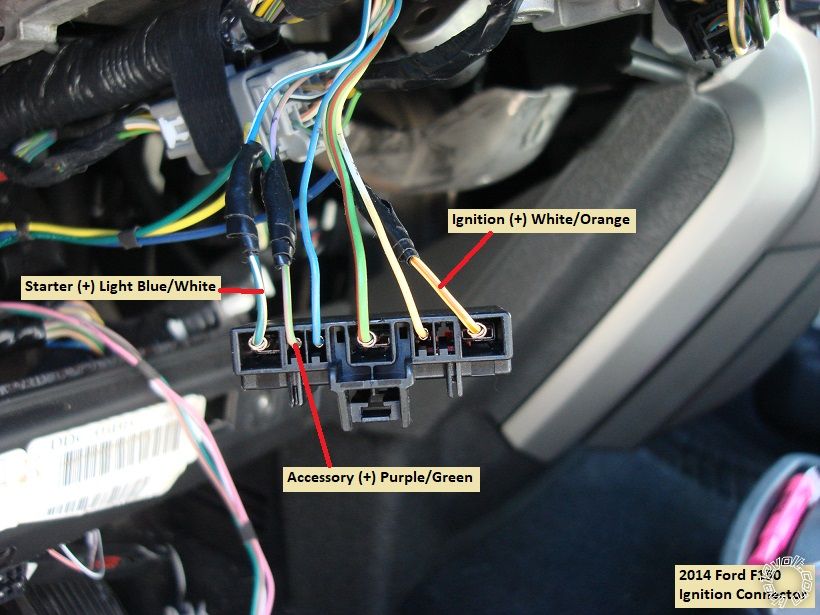
Here is a close up of the ignition wires. I chose not to use the +12V constant wire in the main ignition
harness but there is one there, Green/Red at center position.
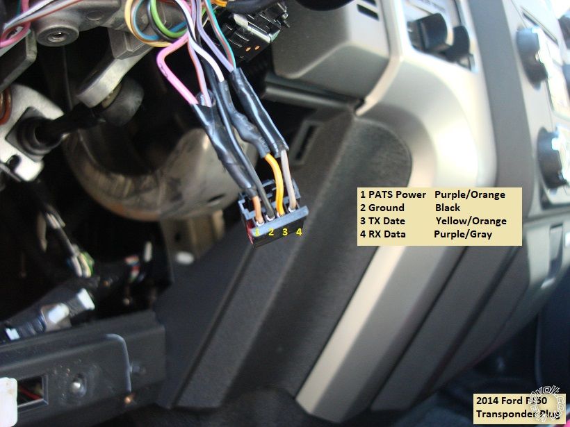
This is a close up of the transponder harness with the wires marked :
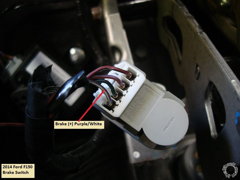
At the top of the brake pedal assembly is the brake switch and the Brake wire. Photo below :
The rest of the wires are found at the BCM in the Passenger Kick Panel. Depending on where the
R/S is located, several wires will have to be extended to reach their connection points.
This is a photo of the BCM with the wires marked :
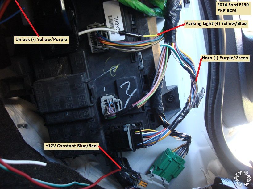
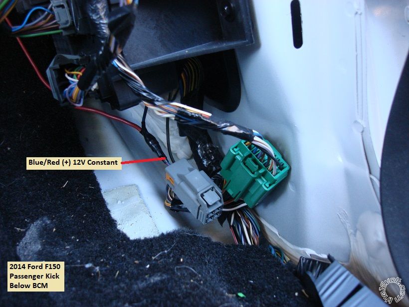
Here is a picture of the +12V power source I used. This was an unused connector below the BCM.
I combined the Avital 4113 two Red +12V input wires into one, fused it down to 20 Amps and made
the connection to the wire shown below :
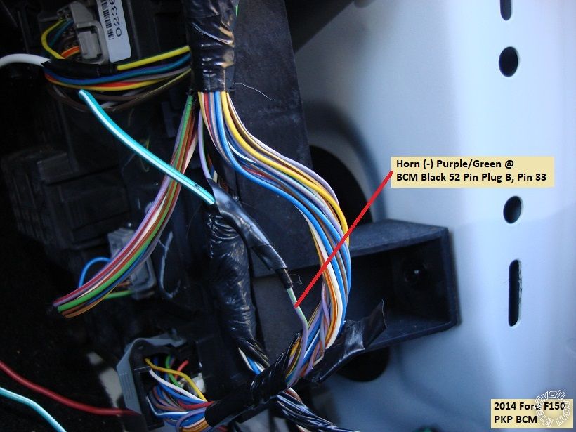
Here is a shot of the optional Horn wire found in the Black 52 Pin Plug marked B on the BCM :
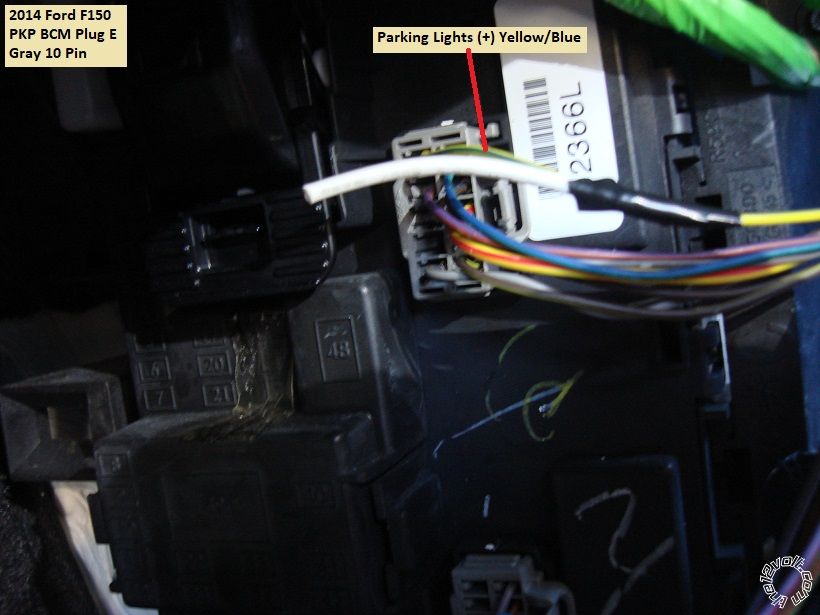
Next is a photo of the (+) Parking Light wire found at the Gray 10 Pin BCM Plug E :
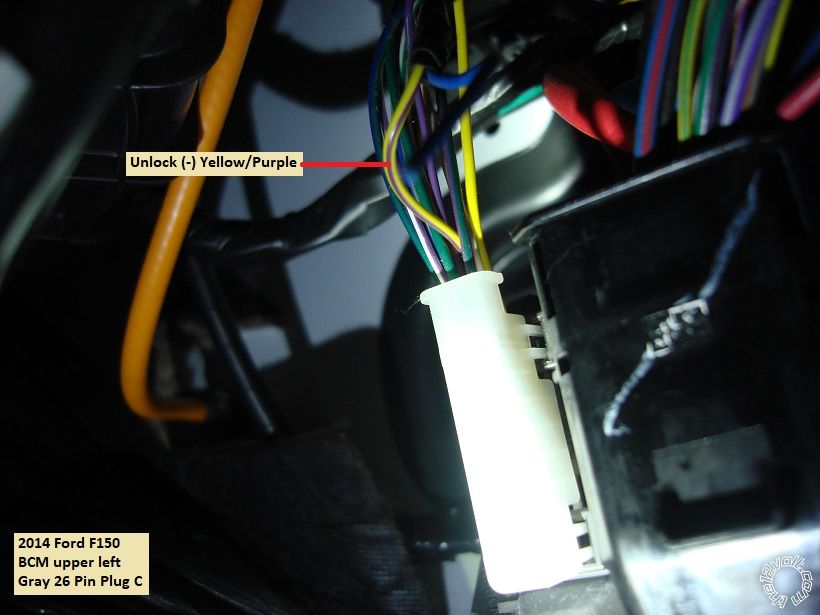
At the upper left corner of the BCM is the Gray 26 Pin Plug C that has the Unlock wire shown below :
Please note that the Lock wire ( Blue/Green ) is found in that same plug/harness.
Chassis ground connection points are readily available as are firewall pass-though points for the hood
pin. If you use a remote start unit that can handle the trucks (-) N.C. hood pin, that signal is available
at the Brown 26 Pin Plug F, Pin 2 at the BCM or at the hood sensor in the engine compartment, it's
a Blue/Orange wire.
There are many ways to incorporate a remote start system into the F150. This setup is very basic and
fairly inexpensive. Being as the factory remotes are part of the key and they still function during remote
start engine run time a simple one button system is all that is needed. This also precludes any special
disarm routine because a remote start up will disarm the factory alarm and the Avital 4113 can only
perform an Unlock function during remote start run time. Coming in at around $80, this is surely a
great K.I.S.S. upgrade to the F150 ( aka FISO ).
).
Here is the module wiring :
Avital 4113
H1/1 LIGHT GREEN/BLACK FACTORY ALARM DISARM.................not used
H1/2 GREEN/WHITE FACTORY REARM...........................................not used
H1/3 YELLOW (+) IGNITION OUT (TO ALARM).................................not used
H1/4 WHITE/BLUE (-) ACTIVATION INPUT.......................................not used
H1/5 BROWN (-) HORN OUTPUT.......................................................Purple/Green @ BCM Plug B, Pin 33
H1/6 ORANGE (-) GROUND WHEN LOCKED....................................not used
H1/7 RED/WHITE (-) TRUNK RELEASE OUTPUT............................not used
H1/8 BLACK GROUND........................................................................Chassis Ground
H1/9 WHITE (+/-) LIGHT FLASH....................*set to (+)......................Yellow/Blue @ BCM Plug E, Pin 6
H2/1 BLACK/WHITE (-) NEUTRAL SAFETY SWITCH INPUT............Chassis Ground through switch
H2/2 VIOLET/WHITE TACHOMETER INPUT WIRE............................not used
H2/3 BROWN (+) BRAKE SWITCH SHUTDOWN WIRE......................Purple/White @ Brake Pedal switch
H2/4 GRAY (-) HOOD PINSWITCH SHUTDOWN WIRE.......................to kit supplied hood pin or tilt switch
H2/5 BLUE/WHITE (-) 200mA 2ND STATUS/REAR DEFOG................not used
4-pin satellite harness diagram
1 BLUE STATUS OUTPUT..................................to PKTX Blue wire
2 ORANGE (-) ACCESSORY OUTPUT..............not used
3 PURPLE (-) STARTER OUTPUT......................not used
4 PINK (-) IGNITION OUTPUT............................not used
Heavy gauge relay wiring diagram
1 PINK (+) (30 AMP) OUTPUT TO IGNITION CIRCUIT.............................White/Orange @ Ignition switch harness
2 PURPLE (+) (30 AMP) OUTPUT TO STARTER CIRCUIT.......................Light Blue/White @ Ignition switch harness
3 ORANGE (+) (30 AMP) OUTPUT TO ACCESSORY CIRCUIT................Purple/Green @ Ignition switch harness
4 RED (+) (30A) HIGH CURRENT 12 INPUT..............................................Blue/Red at connector below BCM @ 20 Amps
5 PINK/WHITE (+) PROGRAMMABLE OUTPUT.........................................not used
6 RED (+) (30A) HIGH CURRENT 12V INPUT.............................................combined with Red Pin 4 wire
Door lock harness, 3-pin connector
1 GREEN (-) LOCK OUTPUT...............not used
2 EMPTY...............................................NOT USED
3 BLUE (-) UNLOCK OUTPUT............Yellow/Purple @ BCM Plug C, Pin 8
PKTX bypass module wires ( link to PKTX install guide :
https://directechs.blob.core.windows.net/documents/pktx_revgcg20140402-cg.pdf )
4 Pin connector ( cut end with red plug )
Red to +12V at 4113 thick Red +12V input
Black to Chassis Ground at 4113 H1/8
6 Pin connector
Purple/White Purple/Gray @ transponder plug, Pin 4
Yellow/Black Yellow/Orange @ transponder plug, Pin 3
Blue Blue @ 4113 4 Pin Satellite connector
Green not used
Pink Purple/Orange @ transponder plug, Pin 1
Black not used
As always, use a Digital Multi Meter to locate and verify vehicle wires and make all your connections with a quality solder joint.
-------------
Soldering is fun!
transmission, Factory Remote Keyless Entry and Factory Alarm. Similar 2011 through 2014 models
should be the same.
Notes on this truck :
The Factory Remote Keyless Entry continues to function during remote start run time.
The ECM controls engine start up ( "one-touch starting"). No Tach signal needed. Fixed crank time OK.
Engine has built-in Anti-Grind.
Remote Keyless Entry is part of the keys.
Considering this trucks features, it was decided to use a one button remote start system with compact
remotes. This will simplify the install. An Avital 4113 and a PKTX bypass module was chosen. Note
that these trucks have the SA key and could be either a 40 bit or an 80 bit transponder systems. The
PKTX install guide should be used to determine which transponder system is in use and which
programming steps should be followed to program the bypass module. You will need two working
non-clone keys to successfully program the bypass module. Factory SA key shown below :
Please note that there are many quality remote starter systems and bypass modules that will handle
these trucks. Other choices include the Ultra Start U1172, Compustar CS801-s and the Prestige
APS901E. Bypass modules for DIYers include the Fortin EVO-Key and the PKTX as these bypass
modules come from the factory with the correct firmware preloaded.
These photos were taken during system de-install. Install was done 3 years ago at lease inception.
Disassembly :
Remove the lower dash panel by removing the three 7mm screws at the bottom edge of the panel
as shown in the photo below, then pull the panel straight away at the top edge ( clips at each upper
corner ).
The knee brace is now exposed and can be removed by removing the four 8mm screws indicated in
the photo below.
Next remove the lower steering column cover by removing the three 5.5mm screws shown in the next
photo and then separate the two halves :
Remove the passenger kick panel cover. Next lift the passenger door sill at the front edge then remove
the PKP by pulling it straight back. This will expose the necessary wires found at the BCM. No photos
of this available.
Wires :
The ignition wires and the transponder wires are found in the steering column. Here is a photo of the
left side of the steering column with the two connectors marked :
Here is a close up of the ignition wires. I chose not to use the +12V constant wire in the main ignition
harness but there is one there, Green/Red at center position.
This is a close up of the transponder harness with the wires marked :
At the top of the brake pedal assembly is the brake switch and the Brake wire. Photo below :
The rest of the wires are found at the BCM in the Passenger Kick Panel. Depending on where the
R/S is located, several wires will have to be extended to reach their connection points.
This is a photo of the BCM with the wires marked :
Here is a picture of the +12V power source I used. This was an unused connector below the BCM.
I combined the Avital 4113 two Red +12V input wires into one, fused it down to 20 Amps and made
the connection to the wire shown below :
Here is a shot of the optional Horn wire found in the Black 52 Pin Plug marked B on the BCM :
Next is a photo of the (+) Parking Light wire found at the Gray 10 Pin BCM Plug E :
At the upper left corner of the BCM is the Gray 26 Pin Plug C that has the Unlock wire shown below :
Please note that the Lock wire ( Blue/Green ) is found in that same plug/harness.
Chassis ground connection points are readily available as are firewall pass-though points for the hood
pin. If you use a remote start unit that can handle the trucks (-) N.C. hood pin, that signal is available
at the Brown 26 Pin Plug F, Pin 2 at the BCM or at the hood sensor in the engine compartment, it's
a Blue/Orange wire.
There are many ways to incorporate a remote start system into the F150. This setup is very basic and
fairly inexpensive. Being as the factory remotes are part of the key and they still function during remote
start engine run time a simple one button system is all that is needed. This also precludes any special
disarm routine because a remote start up will disarm the factory alarm and the Avital 4113 can only
perform an Unlock function during remote start run time. Coming in at around $80, this is surely a
great K.I.S.S. upgrade to the F150 ( aka FISO
 ).
).
Here is the module wiring :
Avital 4113
H1/1 LIGHT GREEN/BLACK FACTORY ALARM DISARM.................not used
H1/2 GREEN/WHITE FACTORY REARM...........................................not used
H1/3 YELLOW (+) IGNITION OUT (TO ALARM).................................not used
H1/4 WHITE/BLUE (-) ACTIVATION INPUT.......................................not used
H1/5 BROWN (-) HORN OUTPUT.......................................................Purple/Green @ BCM Plug B, Pin 33
H1/6 ORANGE (-) GROUND WHEN LOCKED....................................not used
H1/7 RED/WHITE (-) TRUNK RELEASE OUTPUT............................not used
H1/8 BLACK GROUND........................................................................Chassis Ground
H1/9 WHITE (+/-) LIGHT FLASH....................*set to (+)......................Yellow/Blue @ BCM Plug E, Pin 6
H2/1 BLACK/WHITE (-) NEUTRAL SAFETY SWITCH INPUT............Chassis Ground through switch
H2/2 VIOLET/WHITE TACHOMETER INPUT WIRE............................not used
H2/3 BROWN (+) BRAKE SWITCH SHUTDOWN WIRE......................Purple/White @ Brake Pedal switch
H2/4 GRAY (-) HOOD PINSWITCH SHUTDOWN WIRE.......................to kit supplied hood pin or tilt switch
H2/5 BLUE/WHITE (-) 200mA 2ND STATUS/REAR DEFOG................not used
4-pin satellite harness diagram
1 BLUE STATUS OUTPUT..................................to PKTX Blue wire
2 ORANGE (-) ACCESSORY OUTPUT..............not used
3 PURPLE (-) STARTER OUTPUT......................not used
4 PINK (-) IGNITION OUTPUT............................not used
Heavy gauge relay wiring diagram
1 PINK (+) (30 AMP) OUTPUT TO IGNITION CIRCUIT.............................White/Orange @ Ignition switch harness
2 PURPLE (+) (30 AMP) OUTPUT TO STARTER CIRCUIT.......................Light Blue/White @ Ignition switch harness
3 ORANGE (+) (30 AMP) OUTPUT TO ACCESSORY CIRCUIT................Purple/Green @ Ignition switch harness
4 RED (+) (30A) HIGH CURRENT 12 INPUT..............................................Blue/Red at connector below BCM @ 20 Amps
5 PINK/WHITE (+) PROGRAMMABLE OUTPUT.........................................not used
6 RED (+) (30A) HIGH CURRENT 12V INPUT.............................................combined with Red Pin 4 wire
Door lock harness, 3-pin connector
1 GREEN (-) LOCK OUTPUT...............not used
2 EMPTY...............................................NOT USED
3 BLUE (-) UNLOCK OUTPUT............Yellow/Purple @ BCM Plug C, Pin 8
PKTX bypass module wires ( link to PKTX install guide :
https://directechs.blob.core.windows.net/documents/pktx_revgcg20140402-cg.pdf )
4 Pin connector ( cut end with red plug )
Red to +12V at 4113 thick Red +12V input
Black to Chassis Ground at 4113 H1/8
6 Pin connector
Purple/White Purple/Gray @ transponder plug, Pin 4
Yellow/Black Yellow/Orange @ transponder plug, Pin 3
Blue Blue @ 4113 4 Pin Satellite connector
Green not used
Pink Purple/Orange @ transponder plug, Pin 1
Black not used
As always, use a Digital Multi Meter to locate and verify vehicle wires and make all your connections with a quality solder joint.
-------------
Soldering is fun!