2002-2004 Toyota Camry Remote Start w/Keyless Pictorial
Printed From: the12volt.com
Forum Name: Car Security and Convenience - Alarm/Remote Start Pictorials
Forum Discription: Installer submitted Alarm, Keyless Entry, and Remote Start Pictorials from our Car Security and Convenience forum.
URL: https://www.the12volt.com/installbay/forum_posts.asp?tid=143770
Printed Date: February 01, 2026 at 5:16 AM
Topic: 2002-2004 Toyota Camry Remote Start w/Keyless Pictorial
Posted By: kreg357
Subject: 2002-2004 Toyota Camry Remote Start w/Keyless Pictorial
Date Posted: November 13, 2017 at 10:12 PM
This is a basic Remote Start with keyless entry Pictorial for the 2002 through 2004 Toyota Camry. This car was a basic 2004 Camry LE with the 4 cylinder engine, automatic transmission, no Factory Alarm, no Auto Headlights and no transponder based engine immobilizer. As such, this Pictorial will not include info on a bypass module and will focus on this particular car and its' specific needs.
Vehicle considerations :
1. No need for a bypass module.
2. Common Type B door locks
3. To duplicate the factory remotes, trunk release should be included but it is a 5 wire REV system.
4. The car has two Ignition wires, two Starter wires and one Accessory wire, necessitating an additional relay.
5. The Factory remotes are in-op while the engine is running. A R/S w/keyless entry is a good idea.
For this install a Compustar CS800-s system was chosen. There are many other systems that will handle this car, such as Prestige APS57E, Avital 4103LX, Viper 4105V and Ultra Start U1272, to name a few. Additional parts include two 10 Amp mini-relays, two inline fuse holders with 10 Amps fuses, two 1N4004 diodes and a mercury tilt switch. The mercury tilt switch is optional as you can use the R/S kit provided hood pin instead.
Please note that Bulldog Security has a great write-up on this vehicle with plenty of photos that should be reviewed and used to assist during the install. Below is a link to Bulldog Security : https://www.bulldogsecurity.com/bdnew/vehiclewiringdiagrams.aspx
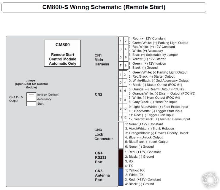
Here is the CS800-s to 2004 Camry that was used :
CM800-s 2004 Camry
CN1
1 Red..................+12V Constant....................................White/Red @ Ignition Harness Pin 7
2 Green/White......+ Parking Light Out.......... ..................not used
3 Red/White........+12V Constant....................................thick Black at fuse box
4 White................+ Accessory.......................................Blue/Red @ Ignition Harness Pin3
5 Blue.................+ Selectable...set to IGN2 via jumper..Black/Yellow @ Ignition Harness Pin 4
6 Yellow.............+ Starter..............................................Black/White @ Ignition Harness Pin 8
7 Green..............+ Ignition.............................................Black/Red @ Ignition Harness Pin 6
8 Black...............Chassis Ground...................................Chassis Ground
CN2
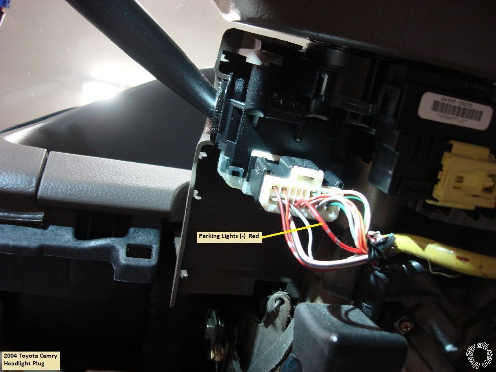
1 Green/White.........(-) Parking Lights..............Red @ Headlight Switch connector
2 Red/Black.............(-) Starter............................to Starter2 Relay Pin 85
3 White/Black.........(-) Accessory.......................not used
4 Black....................(-) Status..............................not used
5 Orange.................(-) Rearm.............................not used
6 Orange/White.....(-) Disarm............................not used
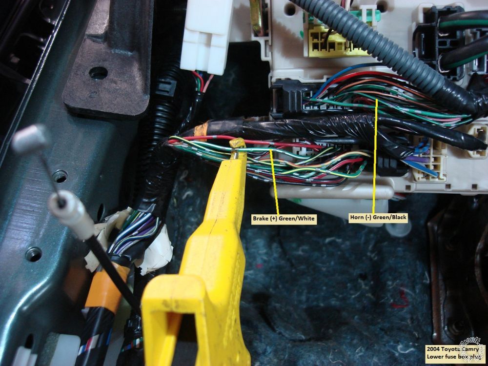
7 White...................(-) Horn................................Green/Black @ 24 Pin connector, lower fuse box
8 Gray/Black.........(-) Hood Pin.........................to mercury tilt switch
9 Lt Blue/White....(+) Brake..............................Green/White @ 20 Pin connector, lower fuse box
10 Red/White........(-) Trigger Start...................not used
11 Red........................(+) Trigger Start..................not used
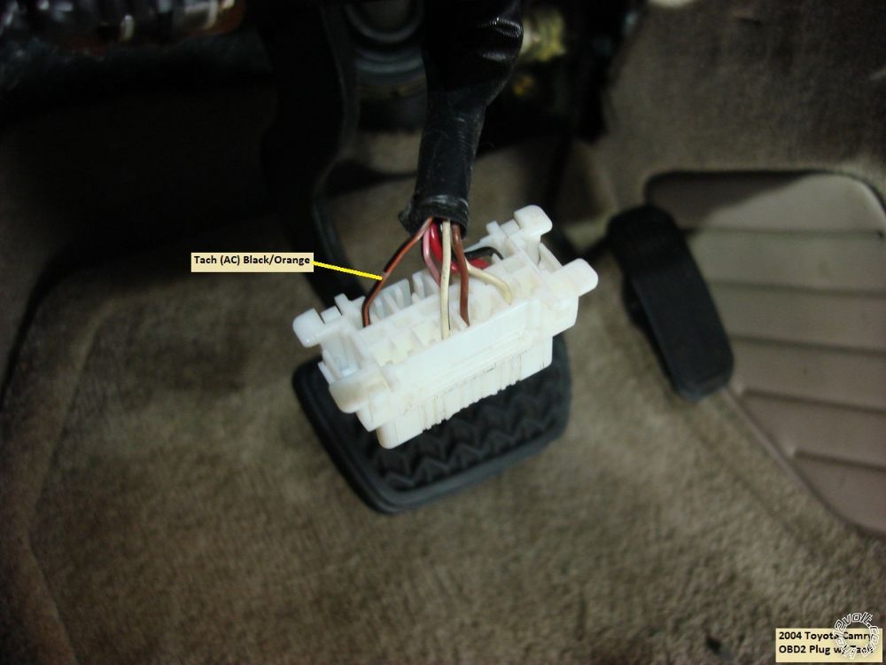
12 Yellow/Black.....Tach.....................................Black/Orange @ OBD2 plug, Pin 9 *
* 4 cylinder engine only
CN3
1 Empty
2 Violet/White..........(-) Trunk Release......................to Trunk Release relay Pin 85
3 Orange/Black.......(-) Driver Priority Unlock...........not used
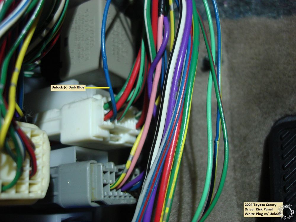
4 Blue......................(-) Unlock..................................Blue @ 20 Pin White connector in DKP **
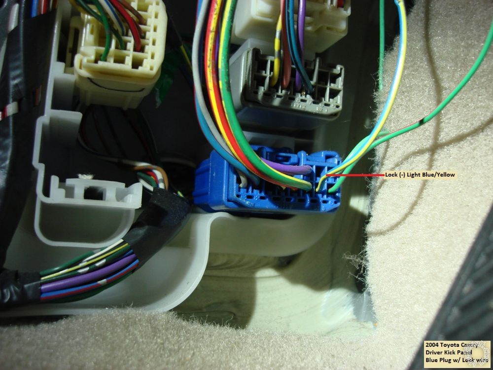
5 Blue/Black............(-) Lock......................................Blue/Yellow @ 12 Pin Blue connector in DKP
6 Empty
** You can program the CS800 for double unlock pulse to unlock all the door with one press of the remotes unlock button or leave it at single pulse and have progressive unlock.
Starter2 Relay
Pin 85 to CS800 CN2 Pin 2 Red/Black
Pin 86 and 87 to +12V Constant @ White wire at ignition connector, Pin 2 through 10 Amp fuse
Pin 30 to Black/Yellow @ Ignition Harness, Pin 1
Trunk Release Relay
Pin 85 to CS800 CN3 Pin 2 Violet/White
Pin 86 and 87 to +12V constant joined with CN1 Red going to White/Red @ Ignition Harness Pin 7 through 10 Amp fuse
Pin 87a to upper side of cut White/Blue Trunk Release wire
Pin 30 to connector side of cut White/Blue Trunk Release wire
Both relays have a 1N4004 diode across Pin 85 to Pin 86 with the band towards Pin 86.
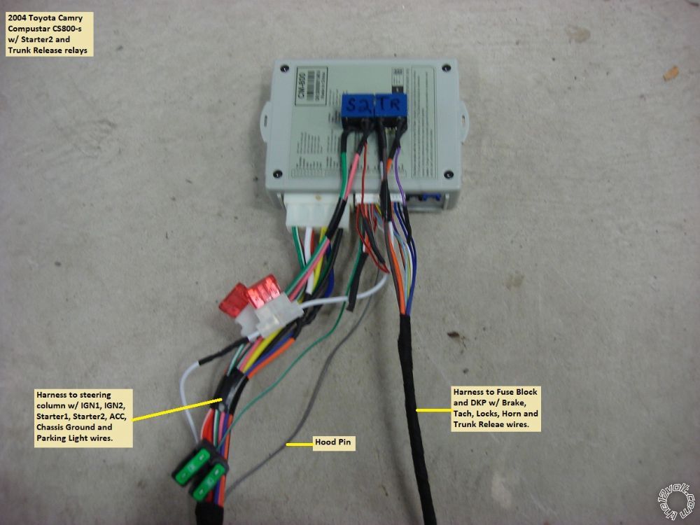
Bench prepped R/S ready for placement and wire connections :
Disassembly :
Lift the leading edge of the driver side door sill panel slightly. Remove the plastic nut at the front of the Driver Kick Panel, then pull the panel towards the right.
Remove the fuse panel cover in the lower driver side dash panel and remove the sliding tray holder above. This will expose one hidden Phillips screw shown in the photo below.
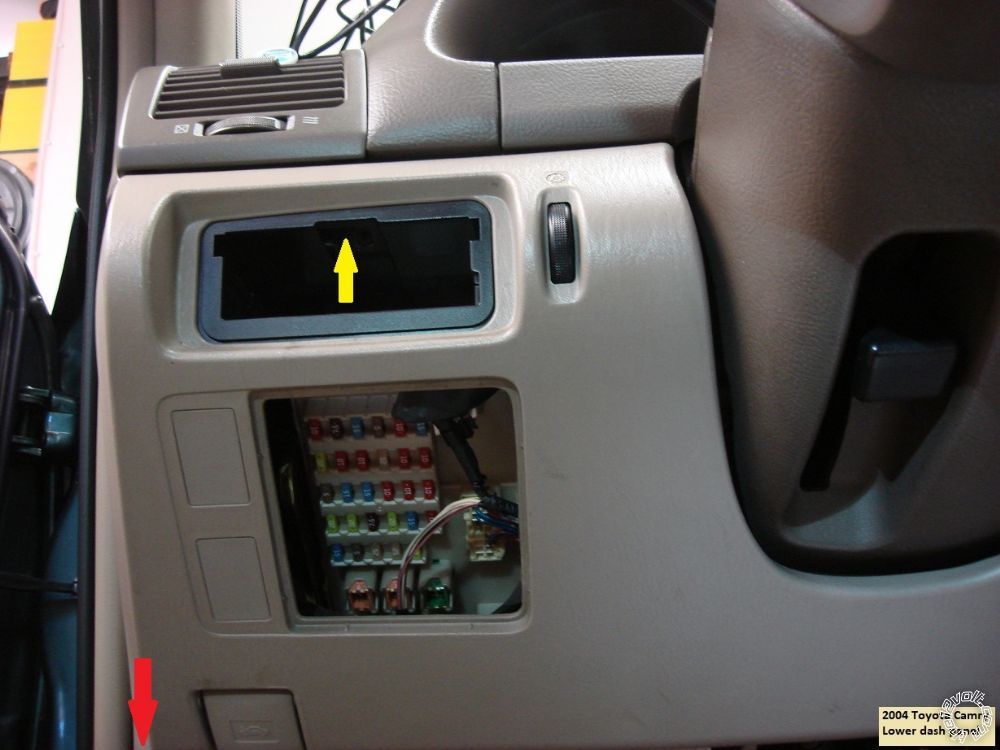
Next remove the hidden screw in the lower dash panel indicated below :
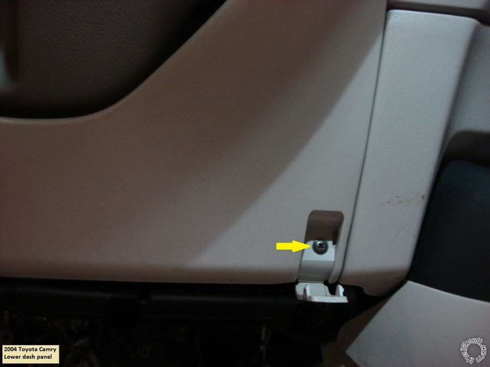
Finally remove the 10mm screw shown in the picture below :
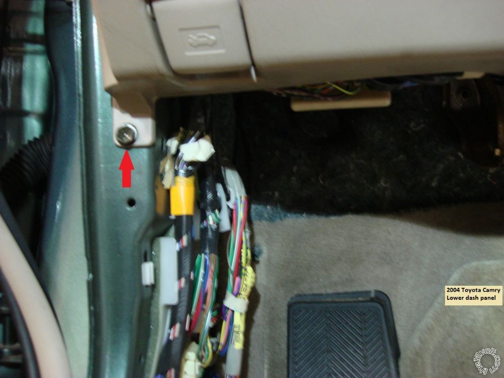
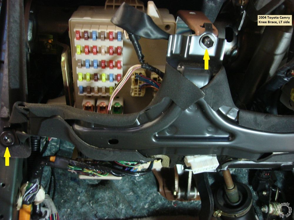
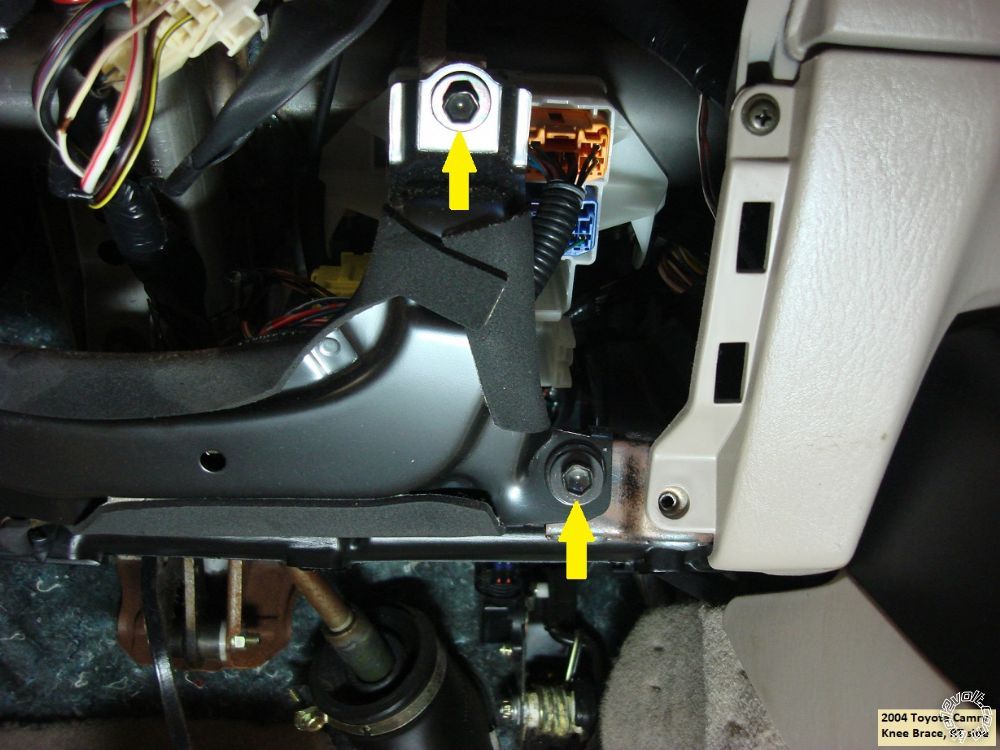
The lower dash panel can now be removed by pulling it straight back and off. This will expose the four 10mm screws shown below that retain the knee brace. The knee brace has the OBD2 plug mount. Just release the OBD2 plug and place the knee brace aside.
Next are the 2 Phillips screws that hold the steering column cover in place. Photo below :
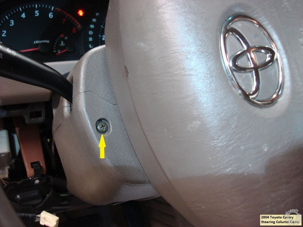
Squeeze the seams to separate the lower steering column cover and remove it.
All of the necessary wires are now exposed.
Wiring :
The ignition switch connector is below the ignition switch and shown in the following photo :
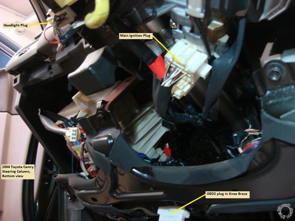
Next is a shot of the ignition switch with the wires numbered :
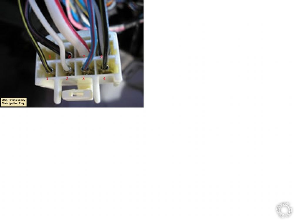
Here is a chart of those wires :
Pin 1 Starter 2..................................Black/Yellow 20 gauge
Pin 2 +12V Constant 10 Amp........White 16 gauge
Pin 3 Accessory................................Blue/Red 16 gauge
Pin 4 Ignition 2.................................Black/Yellow 20 gauge
Pin 5 Empty
Pin 6 Ignition 1.................................Black/Red 14 gauge
Pin 7 +12V Constant 12 gauge......White/Red
Pin 8 Starter 1.................................Black/White 12 gauge
Staying at the steering column, here is a picture of the Headlight plug with the (-) Parking Light wire indicated :
Next we move to the OBD2 plug for the Tach wire :
Going slightly more to the left we come to the lower fuse box plugs for the Brake and Horn wires :
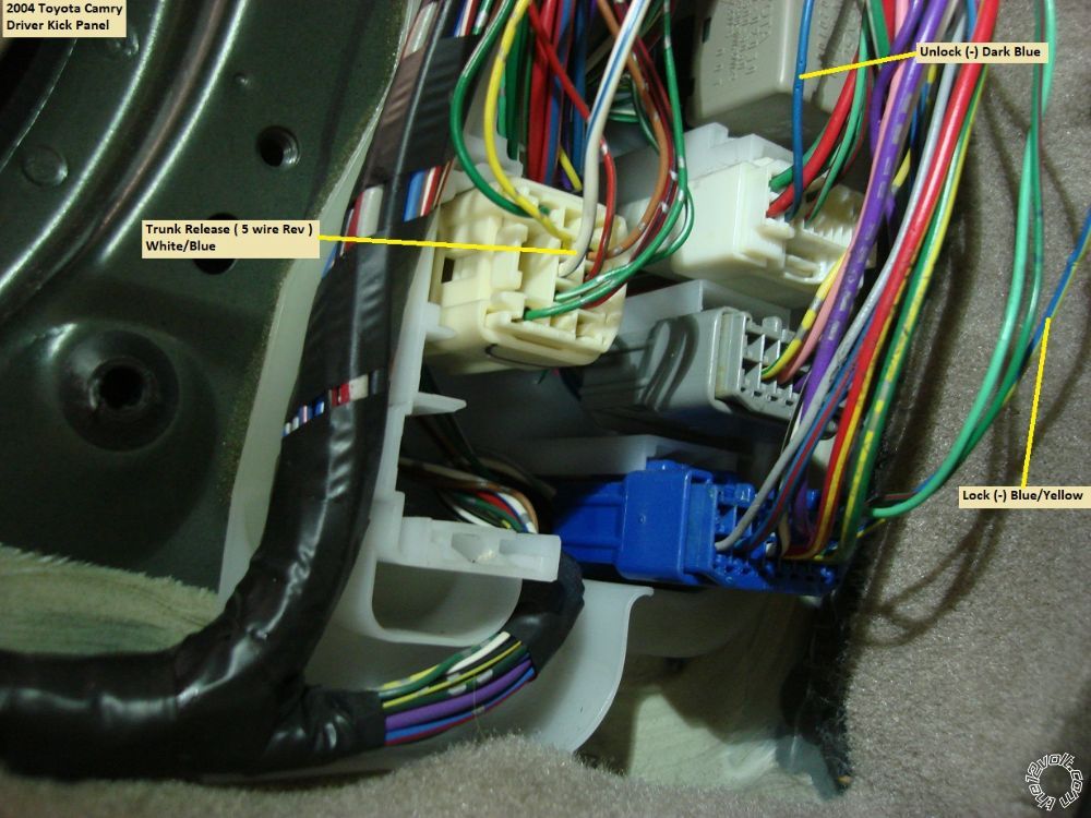
And finally, at the lower Driver Kick Panel we have these wires :
Trunk Release :
Unlock wire :
Lock wire :
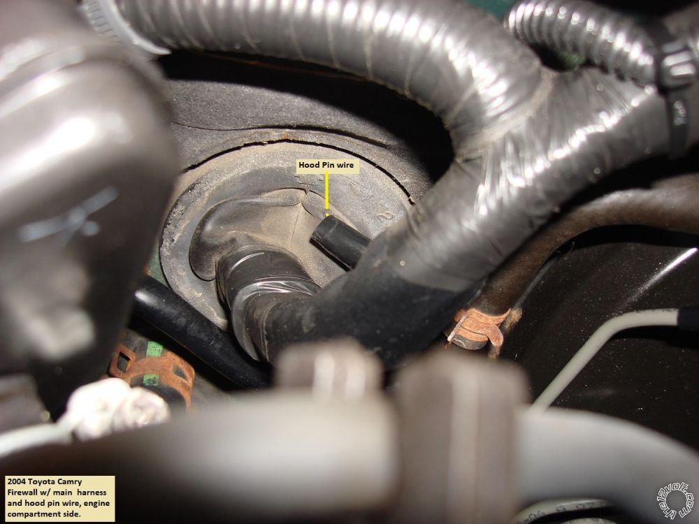
For the hood pin wire, firewall pass through can be had at the main harness grommet located high above the gas pedal. Here is a photo on the hood pin wire coming through that grommet on the engine side :
There are many good places to attach the Chassis Ground wire. I used a self-tapping metal screw and ran it to the heavy dash cross pipe. There is a large cavity behind the fuse box to secure the CS800-s brain.
That about does it for the wiring. There are a few programming changes that should be made to the CS800. To run in Tach Mode change Feature 2-04 to option 2. You must also do a Tach Learn. If you want all doors to unlock at once, change Feature 1-03 to option 2, double unlock pulse. Being as the car does not have a factory alarm system, you can set the trunk to release without first unlocking the doors by changing Feature 1-10 to option 3. If you need a longer R/S run time than the default 15 minutes, see Feature 1-07. Another option you might want to change is the Horn honk, Default is after a second Lock command. See Feature 2-08 for more options.
Test everything and button it up. Remember to use a Digital Multi Meter to test vehicle wires and make all the wire connections with a quality soldered joint. ------------- Soldering is fun!
Replies:
Posted By: monkman911
Date Posted: March 20, 2019 at 11:14 AM
Hey Kreg!
Great info! Getting ready to install a CS4900-s in my 2004 Camry and was wondering if there is much of a difference between the two units. I guessing the basic wiring between the 2 won't differ much.
Thanks in advance!
Posted By: kreg357
Date Posted: March 20, 2019 at 8:00 PM
Good choice! The CS4900-s is a nice unit.
For the most part, the wiring is the same. The CN1 connector is identical between the units. The CN2 plug is somewhat similar to your CN3 connector but go by the signal name instead of Pin location. The wire colors are pretty much the same but the Lock and Unlock wires are different colors. Your main issue will be getting a (+) Starter2 Output from the CS4900-s to properly power the Camry's Starter2 circuit. The CS800-s makes this easy with a dedicated (-) Starter Output that I used to control a mini-relay. The CS4900-s can do the same thing but would need a programming change to Special Option Group 2. You could re-assign either of the unused Rearm or Disarm POC outputs to be a Starter output. The big problem is that you would need the OP-500 programmer to do this. It can't be done with the remotes like you use to change options in Groups 1 through 4. Now for the really bad news, the OP-500 goes for around $100. There is a way around this if you don't mind a bit of extra wiring.
Remember, the goal is to supply the cars two (+) Starter wire with separate, isolated power, so you can't just connect the CS4900-s thick Yellow wire to both vehicle starter wires. Buy two 30/40 Amp SPDT relays with pre-wired sockets, two inline fuse holders and a 25 amp and a 10 amp fuse. Figure about $15 for the parts. Here is the wiring :
Starter 1 Relay
Relay Pin 85 to Chassis Ground
Relay Pin 86 to CS4900-s CN1 Yellow Starter output
Relay Pin 87 to +12V constant through 25 amp fuse
Relay Pin 30 to Camry Black/White Starter1 wire, Pin 8 of main ignition connector
Starter 2 Relay
Relay Pin 85 to Chassis Ground
Relay Pin 86 to CS4900-s CN1 Yellow Starter output
Relay Pin 87 to +12V constant through 10 amp fuse
Relay Pin 30 to Camry Black/Yellow Starter2 wire, Pin 1 of main ignition connector
You will use the CS4900-s Starter output to control two relays. Each relay will supply isolated power to one of the Camry's Starter circuits.
You must test the ignition wires because there are 2 Black/Yellow wires. One is an Ignition type wire and the other is a Starter wire.
You're going to need a relay for the Trunk release so you might as well get a 4 pack of relays off EBay for ~$10. Search on "30/40 Amp SPDT relay 4 pack" and get the ones that come with harness socket.
Remember that the Tach wire shown at the OBD2 connector is for 4 cylinder Camry's only. Also verify that your Camry does not have transponder chipped keys. If they are, you will need a bypass module to allow a remote start up.
-------------
Soldering is fun!
Posted By: monkman911
Date Posted: March 20, 2019 at 9:14 PM
Thanks Kreg!
Already have the relays, inline fuses and diodes. I plan to wire just like you did and I don't have to worry about a transponder key. LOL on the OP-500, you are right, $100+ for a programming tool that from my research unless you are a registered installer, they won't even let you update the firmware. I'll stick to changing options with the remote. My Camry is the 4 cylinder model so I don't foresee any issues. I'll be careful to double check the function of the wires for CON2/3. I laugh when I read reviews about having R/S only being installed by pros. I live in a small college town and I wouldn't trust these shops to install windshield wipers. They prey on the college kids and they figure if they ever changed out the stereo in a car, they can open a tint/R/S/stereo shop. A little common sense goes a long way.
Thanks again for the insight, I'll let you know how it turns out this weekend. I do have 1 question though. I plan to run tachless, which I believe is the default. Did you run into any issues with the way you set your Camry up? Also I think I can get by with only 1 starter relay, CON1 pin 5 blue wire can be configured by jumper to be ING, ACC or START. ING is default so I figure I put the jumper for START and run that wire to the STARTER 2 relay. Thoughts?
Cheers!
Posted By: kreg357
Date Posted: March 20, 2019 at 9:41 PM
Personally, I always run in Tach Mode. With the Tach wire so easily accessible inside the car, you really should make that connection. Tach Mode is much more reliable getting consistent starts, especially in cold climates where the seasonal changes vary by 90 plus degrees.
You are already using the CN1 Pin 5 Blue wire for the Camry's IGN2 circuit. As mentioned above, that car has two Ignitions, two Starters and one Accessory wire that should be powered during remote start. I have heard that powering both ignitions from one R/S wire will blow a fuse in the engine compartment that will get the car towed back to the install shop. A little extra time adding the two starter relays during bench prep is the safe way to go.
I encountered no issues with those Camrys. They respond well to the aftermarket system. The only minor hurdle was finding and verifying the Trunk Release wire. You need a working Factory FOB to trigger that signal. They are fast and easy to do without an alarm system or need for a transponder bypass module.
-------------
Soldering is fun!
Posted By: monkman911
Date Posted: March 20, 2019 at 10:39 PM
Yep, you're right, I completely spaced the IGN2. I'll prep the harness Friday night and do the install Saturday. What is the best way to attach the diodes? Do you solder them to the blades on the relay or just to the wires for pin 85 and 86?
Thanks again Kreg!
Posted By: kreg357
Date Posted: March 21, 2019 at 5:06 AM
For the relay quenching diodes, I add them to the 5 Pin wire harness as shown near the end of this Pictorial : https://www.the12volt.com/installbay/forum_posts.asp?tid=133810
Keeps everything neat and, of course, I like to solder.... ;)
If you have the supplies available, you can use thinner gauge wire for the IGN2 and Starter2 ignition wires. Makes the soldered connection easier and provides a compact bundle of wires going to the steering column.
Good luck with the install.
-------------
Soldering is fun!
Posted By: monkman911
Date Posted: March 21, 2019 at 10:18 AM
You are the man Kreg! I was just looking at the CN3 harness and I might be screwed for the trunk release without having to get my hands on an OP500. I don't see a wire that by default will trigger the trunk. CN4 has everything I need so what I might do is scrounge up a connector that will work with that. The CM900 does not come with a wiring harness for CN4, it is optional for people upgrading from the CM800. Have a great day and I'll update you this weekend!
On a side note, I thought I was the only person in the universe using a Circuit Buddy! :D
Posted By: kreg357
Date Posted: March 23, 2019 at 10:47 AM
Forgot about the Trunk Release being on CN4. I have the OP-500 so it's no problem for me. I also have a bunch of unused harness. I can send you a CN4 harness if you need. Just PM me your mailing address.
I get a lot of use out of my Circuit Buddy. Great probe with nice features. A PowerProbe would be nice but I really can't justify the cost.
-------------
Soldering is fun!
Posted By: monkman911
Date Posted: March 23, 2019 at 4:10 PM
I got it covered but thanks for the offer! I have a lot of wiring harnesses of different types left over from years of doing stereos for friends. Install is almost done, just have to hook up the locks and trunk and were should be ready to test.
Thanks kreg!
Posted By: monkman911
Date Posted: March 24, 2019 at 3:40 PM
Hey Kreg,
Update, got the system installed and running.I do have a real brain scratcher though. When I lock the car, the trunk opens.I triple checked the trigger wire going to the relay and it is from the correct pin on CON4. Also I can't program the options. I hooked up the tach like you suggested but need to change 2-10 to run in tach mode. Here is what I am doing:
Hood open to disarm system
Lock+Unlock for 3 seconds wait for flash
Lock+Key for 3 seconds wait for flash
Tap Key button to get to the option in menu 2 I want to change
I can tap the key 3 times waiting each time for the confirmation flash and when I get to 2-4, the car will flash 3 times and won't let me go any farther
I am hitting the Key button immediately after each flash.
Any thoughts?
Thanks again for all of the help!
Posted By: kreg357
Date Posted: March 24, 2019 at 6:07 PM
For the Trunk issue, double check your CN4 connection. It's possible that you got the pin sequence reversed. It goes like this :
CN4
1 Empty
2 Violet/White...(-) Trunk Release
3 Orange/Black...(-) Driver Priority Unlock
4 Blue....……...(-) Unlock
5 Blue/Black...….(-) Lock
6 Empty
Pin 6 is at the bottom of the controller and Pin 1 is next to CN5. If that is the way you have it, try switching it to the second from the bottom.
For the CM900-s programming, I really can't help much. Using the remotes is rather arduous so I spent the money for the OP-500 programmer. Makes life much easier. I can also set the options with the ADS USB cable on-line ( even without a Blade module plugged in ).
I'm pretty sure the CM900-s comes in Tach Mode but the install guide is very confusing. It mentions MT Mode but they should be Auto Trans only. The write up doesn't match the Tables shown.
As for other necessary programming, I would set 1-07 to opt 3 for the Trunk.
-------------
Soldering is fun!
Posted By: monkman911
Date Posted: March 25, 2019 at 1:42 PM
Looks like they reversed the pin labeling on the CM900 LOL!
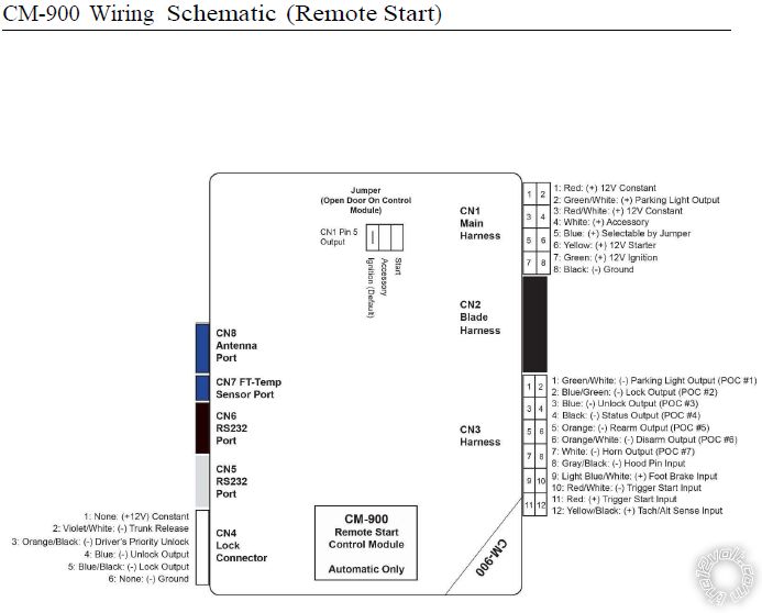
I found a used OP500 on EBay, should be here later this week. I love this R/S, I came into work today and was able to start it through 4 walls and having my car parked at the back of the lot (300 feet I'm guessing). The factory FOB for Toyota normally takes a 2 second press to unlock the trunk so I'm thinking along with changing 1-10 to option 3 also changing 1-09 to option 3.
Thanks Kreg!
Posted By: kreg357
Date Posted: March 25, 2019 at 6:48 PM
Double check you programming guide. Looks like you are using the CM800-s and not the CM900-s version. The 2 second Trunk Release pulse won't make it open faster, it's just a longer output for those cars that won't pop the trunk with a one second pulse.
Well, if you are going to get the OP-500, you might as well make good use of it. Below is the info for the Rear Defroster :
Rear Defrost YELLOW/GREEN (-) 8 PIN CONN, FRONT RIGHT OF FUSE/JUNC BOX
The Yellow/Green wire will test as (-) when the rear defroster is turned ON.
You can set one of your un-used POC's to Option 17 - Defrost and set 3-14 to Option 3 for a seven minute latched output. Connect that POC wire to the Yellow/Green and you are all set, unless you wanted to get a Temp Sensor and plug that into CN-7. With the Temp Sensor you can use 3-13 to select a turn on temperature. :)
-------------
Soldering is fun!
Posted By: monkman911
Date Posted: March 25, 2019 at 8:26 PM
Yep, you're right, I was looking at the CM800 table instead of the CM900 when I was posting that. Since I have to get back in the dash to hook up the trunk correctly, I am going to take your suggestion and hook up the defrost. Is there a reason for 3-14 option 3 instead of 4?
Posted By: kreg357
Date Posted: March 26, 2019 at 5:23 AM
No, not really. Seven minutes usually does it, but the entire R/S run time won't hurt anything.
Being as your car doesn't have a Factory Alarm system, there is no reason to unlock the doors prior to a Trunk Release. Think I mentioned that programming change previously.
-------------
Soldering is fun!
Posted By: monkman911
Date Posted: March 26, 2019 at 10:12 AM
Before I hook up the defrost, i would like to include a temp sensor because I would rather not have that running in the summer. A quick Google search yielded nothing. What am I looking for specifically?
Thanks Kreg!
Posted By: monkman911
Date Posted: March 26, 2019 at 11:45 AM
Disregard, I was able to find one from Lock Down Security in Canada, $9.99 CAD.
Posted By: kreg357
Date Posted: March 26, 2019 at 4:16 PM
Cheaper than Ebay for $19.99.
-------------
Soldering is fun!
Posted By: monkman911
Date Posted: March 28, 2019 at 1:44 PM
Hey Kreg! Have you figured out how to hook up the horn trigger to the car module that sounds when you use the factory remote? I am not a big fan of the horn honking for the lock and start functions, I would prefer the soothing sound of the factory chime.
As always, I greatly appreciate your expertise and guidance!
Posted By: kreg357
Date Posted: March 28, 2019 at 1:56 PM
I've never tried to do that, mostly because everything I've read about other peoples attempts were unsuccessful.
-------------
Soldering is fun!
Posted By: monkman911
Date Posted: March 28, 2019 at 2:01 PM
Fair enough, I'll set 3-02 to option 2 and hope it's not too obnoxious :-)
Posted By: monkman911
Date Posted: March 29, 2019 at 7:24 PM
Update Kreg! Finished the install and everything works great. You were right, even though the manual says that engine sensing is default, it is actually tach mode. The OP500 worked flawlessly. What a time saver, I don't know if I'll ever install another Compustar, but I'll be ready if I do.
Thank you again!
Posted By: kreg357
Date Posted: March 29, 2019 at 8:06 PM
Once word gets out about your R/S install, all your friends and relatives will want one too. You'll need the OP-500 for them. ;)
Enjoy your new and improved Camry!
-------------
Soldering is fun!
Posted By: volt_amba
Date Posted: February 03, 2020 at 3:08 PM
Hey Kreg, which one is the "thick black at fuse box"? is it one of the 2 the black and green wires?
can i just use the 12V constant white/red at ignition? or maybe not because of current limitations?
Posted By: kreg357
Date Posted: February 04, 2020 at 2:04 PM
You are correct on several points. The ignition wires are supplied by 2 different wires in the plug. One is thin and can only handle 10 Amps. That wire provides current for either Starter2 or IGN2 which are also thin wires. The "thick Black wire at the fuse box" is actually two Black/Green wires as shown in one of the photos. Depending on the system you are installing you can split up the +12V inputs between those vehicle wires.
-------------
Soldering is fun!
Posted By: volt_amba
Date Posted: March 17, 2020 at 5:57 PM
although it took me some time (and figuring out a few things) i was able to install this and get it to work. thanks for your guide, I wouldn't have attempted this without it.
Posted By: kreg357
Date Posted: March 18, 2020 at 9:07 AM
Thanks for the update. Glad you are pleased with the results. Enjoy your new and improved Camry!
-------------
Soldering is fun!
Posted By: volt_amba
Date Posted: March 27, 2020 at 11:21 AM
actually a quick question. the car unlocks all doors on a double pulse but i am seeing it is very finicky on getting the right timing between the double pulse. i was wondering if there is an option to unlock all doors at the first pulse? i briefly checked the manual but didn't find anything.
Posted By: kreg357
Date Posted: March 27, 2020 at 5:45 PM
Are talking about using the Factory remotes or an aftermarket remote that came with a R/S system?
-------------
Soldering is fun!
Posted By: volt_amba
Date Posted: March 28, 2020 at 5:56 AM
R/S system. i am using CS800.
Posted By: kreg357
Date Posted: March 28, 2020 at 7:58 AM
With the CS800-s, the easiest way to get all the doors to unlock with just one press of the aftermarket FOB's Unlock button is to change the CS800-s programming to output a "double unlock pulse". The timing should be correct for the Camry and unlock all the doors with its' two unlock pulses. When set, you will actually hear two unlocks. First the Drivers door and then a split second later the rest of the doors. In the install guide, see programming feature 1-03. Factory Default is OFF. You want to change it to Optional Setting-II, which will provide two unlock pulses with a single press. The install guide also details how to use the remotes to make the change.
Short of that, on Toyota's, there is usually a wire in the Passenger Kick Panel that is the Unlock signal from the Passengers Door switch that will unlock all doors with a single pulse. This would require a wiring change and extending the CS800-s Unlock wire for the longer trip to the PKP area. I believe I used this method on the 2005 Toyota Sienna Pictorial but the wire color and plug location would be different.
In my local area, with a female driver, I always leave progressive unlock ON unless specifically requested otherwise. Provides better parking lot / parking garage safety.
-------------
Soldering is fun!
|


