2015-2018 Ford Transit Remote Start Pictorial
Printed From: the12volt.comForum Name: Car Security and Convenience - Alarm/Remote Start Pictorials
Forum Discription: Installer submitted Alarm, Keyless Entry, and Remote Start Pictorials from our Car Security and Convenience forum.
URL: https://www.the12volt.com/installbay/forum_posts.asp?tid=145130
Printed Date: May 23, 2026 at 9:31 PM
Topic: 2015-2018 Ford Transit Remote Start Pictorial
Posted By: kreg357
Subject: 2015-2018 Ford Transit Remote Start Pictorial
Date Posted: January 01, 2019 at 8:41 PM
This is a quick no-frills Remote Start Pictorial on the 2015 - 2018 Ford Transit. These are the full size replacements for the Econoline series of vans, not the smaller Transit Connect series. This install will cover the common work vans, not the passenger vans with many rows of seats. This van was a 2017 Transit 250. It had the 3.7 L engine, no Factory Alarm system and no PATS engine immobilizer system. Most work vans do not come with the PATS system. The van did have power locks and "one-touch" starting. The factory key FOB's include the power lock control buttons and continue to function during a remote start-up so a simple One Button Remote Start system was chosen to provide a bit of extra range over the factory remotes and a 3x Lock system.
There are many brands and models or R/S system to choose from. The Avital 4113 / 4115 and the Viper equivalents, Compustar CS801-s and CS910-s and the Prestige APS901E or the newer APS901Z are all excellent low cost 1-way units. For this install I used an Avital 4115. No PATS system means no bypass module, less money and a very simple install.
While this Pictorial includes photos of the lower dash removal, I would recommend that before attempting this install you visit YouTube and do a search on "2015+ transit remote start". There is a 14 minute video posted that shows all the necessary trim panel removal in good detail.
Disassembly :
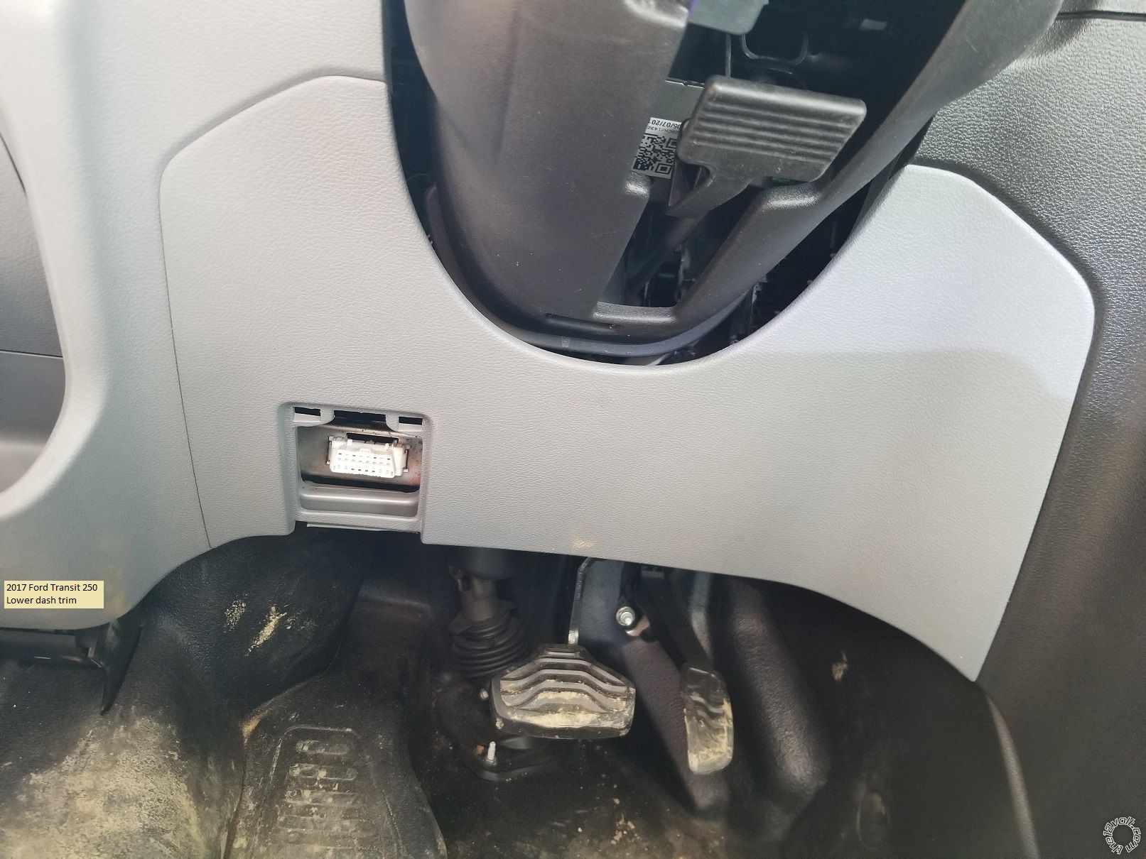
First pull the trim panel below the steering wheel off.
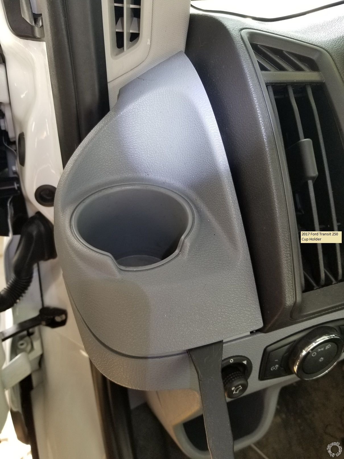
Next use a trim tool to pop the cup holder up and off.
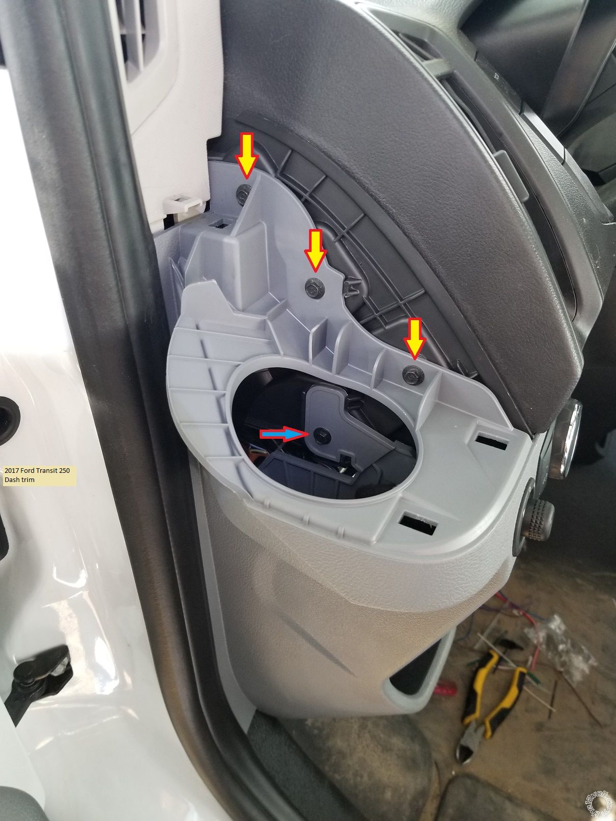
Use a 7mm socket to remove the three screws shown.
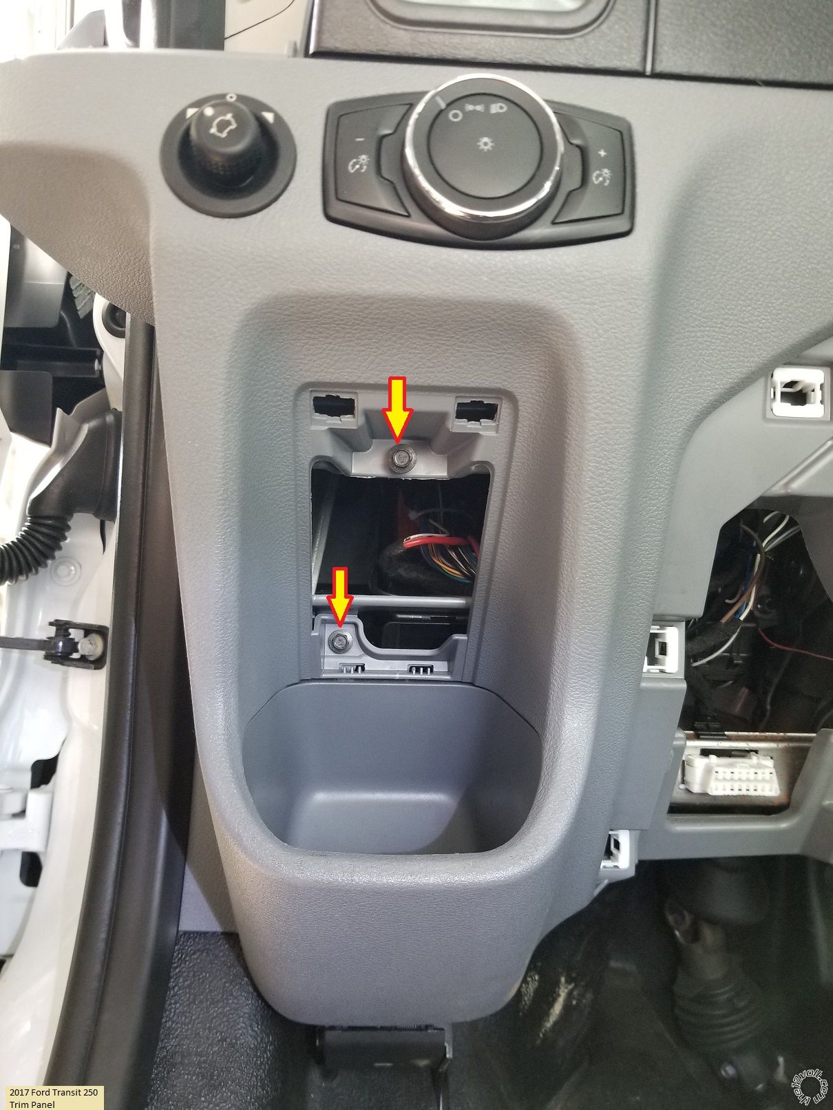
Remove the fuse access panel and then the two 7mm screws indicated.
Release and pull this left side trim piece away from the dash.
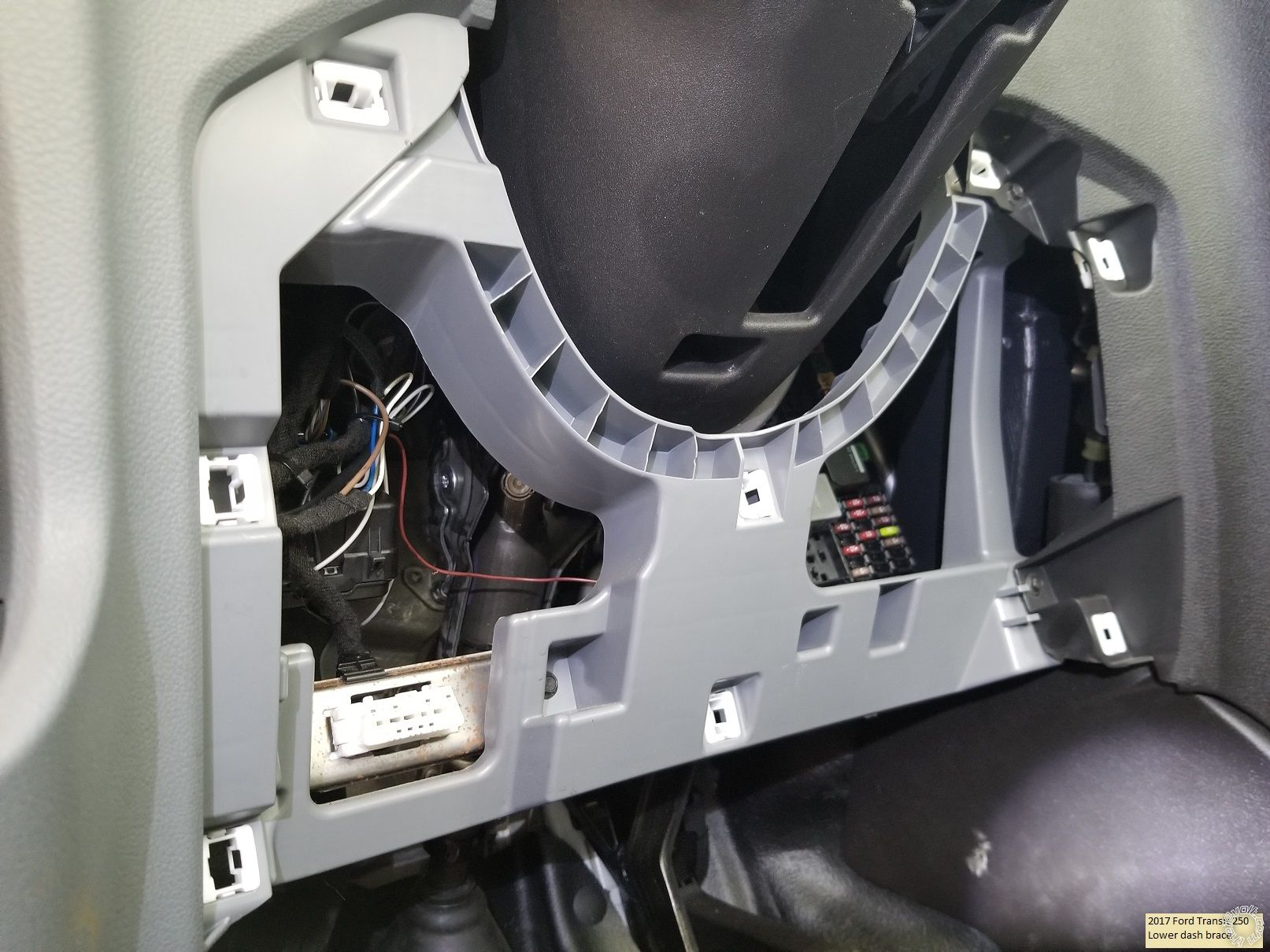
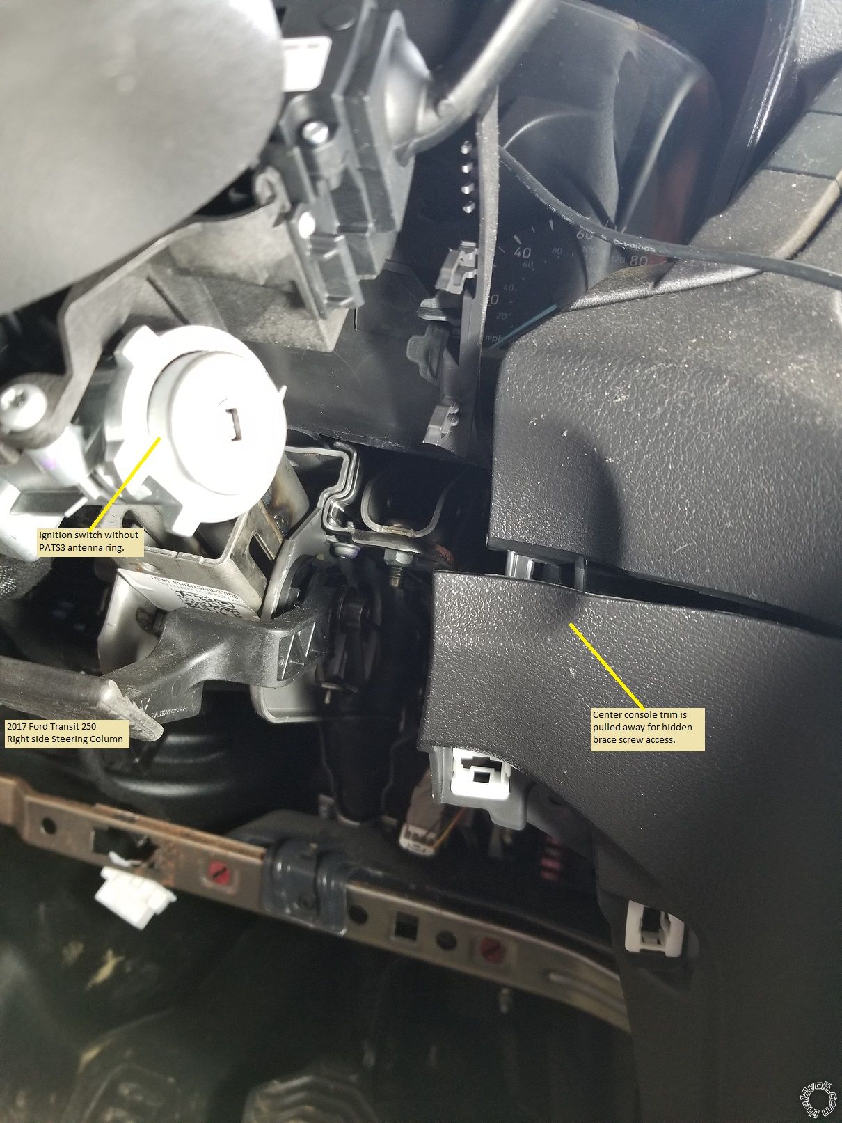
To remove the inner brace panel, remove the seven 7mm screws. This is shown in good detail in the previously mentioned video. One screw is on the left side. You must gently lift the center console trim to access one hidden screw at the top right corner on the brace panel.
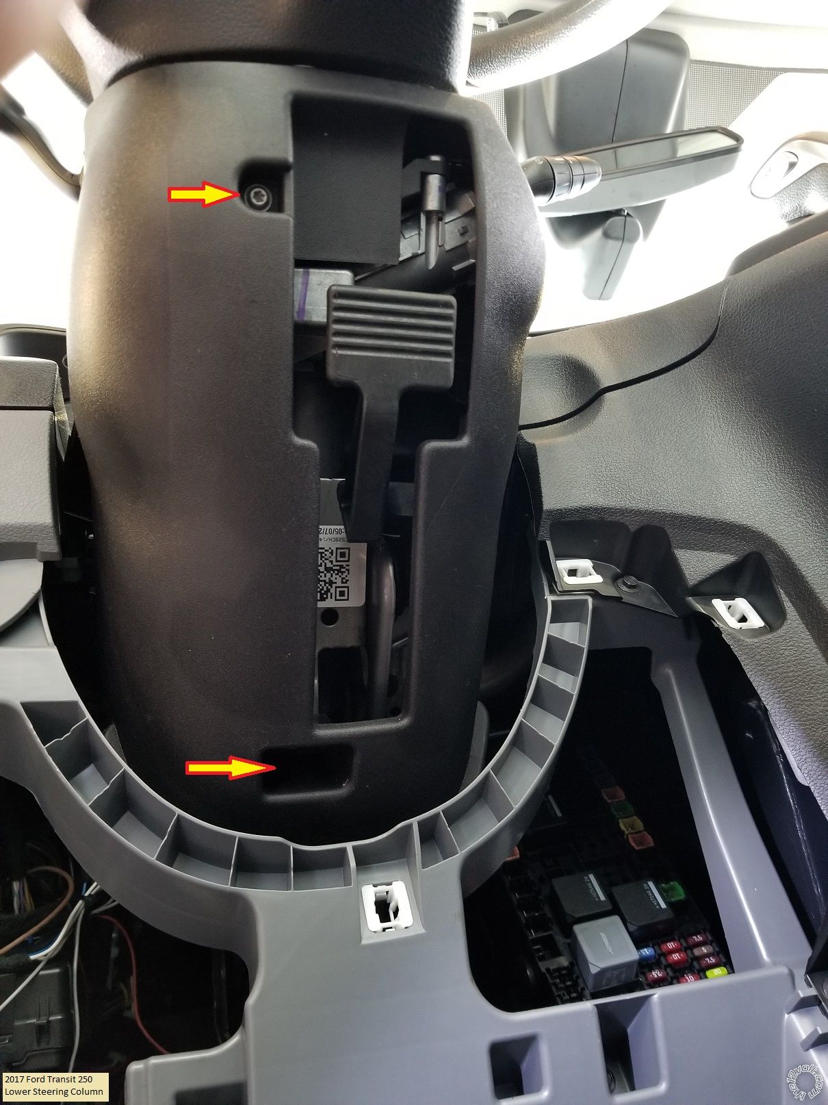
Remove the two T20 Torx screws indicated at the bottom of the steering column. Then turn the steering wheel to expose plastic releases at the 10 and 2 o'clock positions. Separate the steering column cover halves and remove the bottom piece.
That's it for trim removal. At this point you should verify that there is no black plastic PATS antenna and connector on the ignition switch. Below is a photo of this Transit without the PATS system. If you have the PATS antenna, you will need a bypass module.
Wiring :
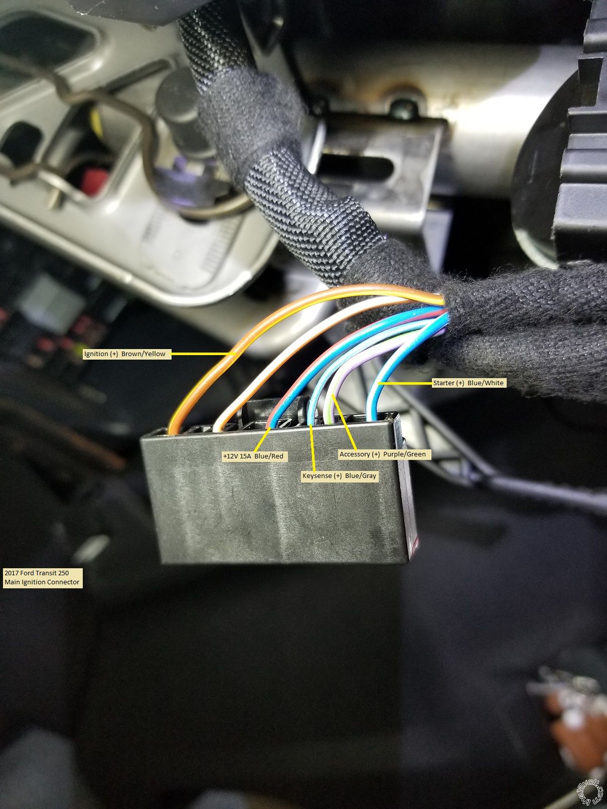
Here is a photo of the main Ignition connector removed from the plug with the wires marked. Only 3 connections are needed, IGN, ACC and Starter.
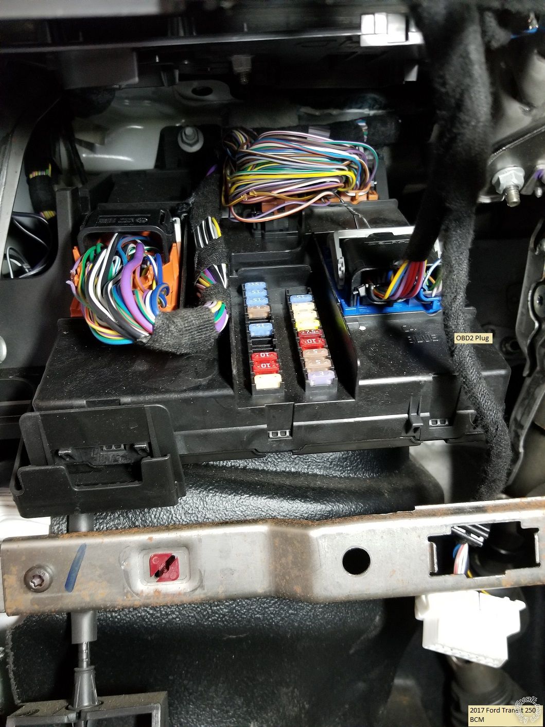
Below is a photo of the vans BCM located to the left of the steering column.
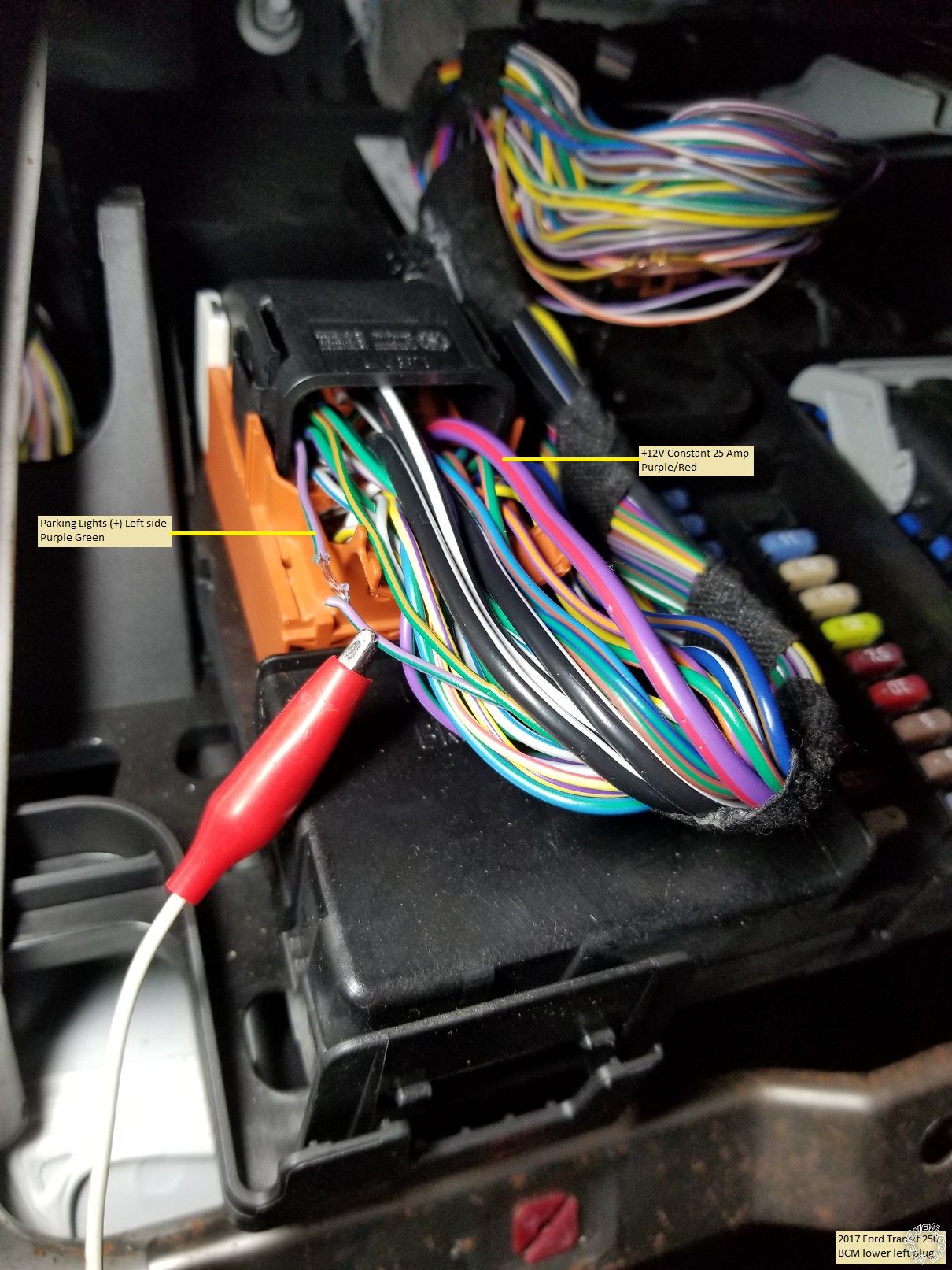
The lower left connector has the left side Parking Light wire as shown.
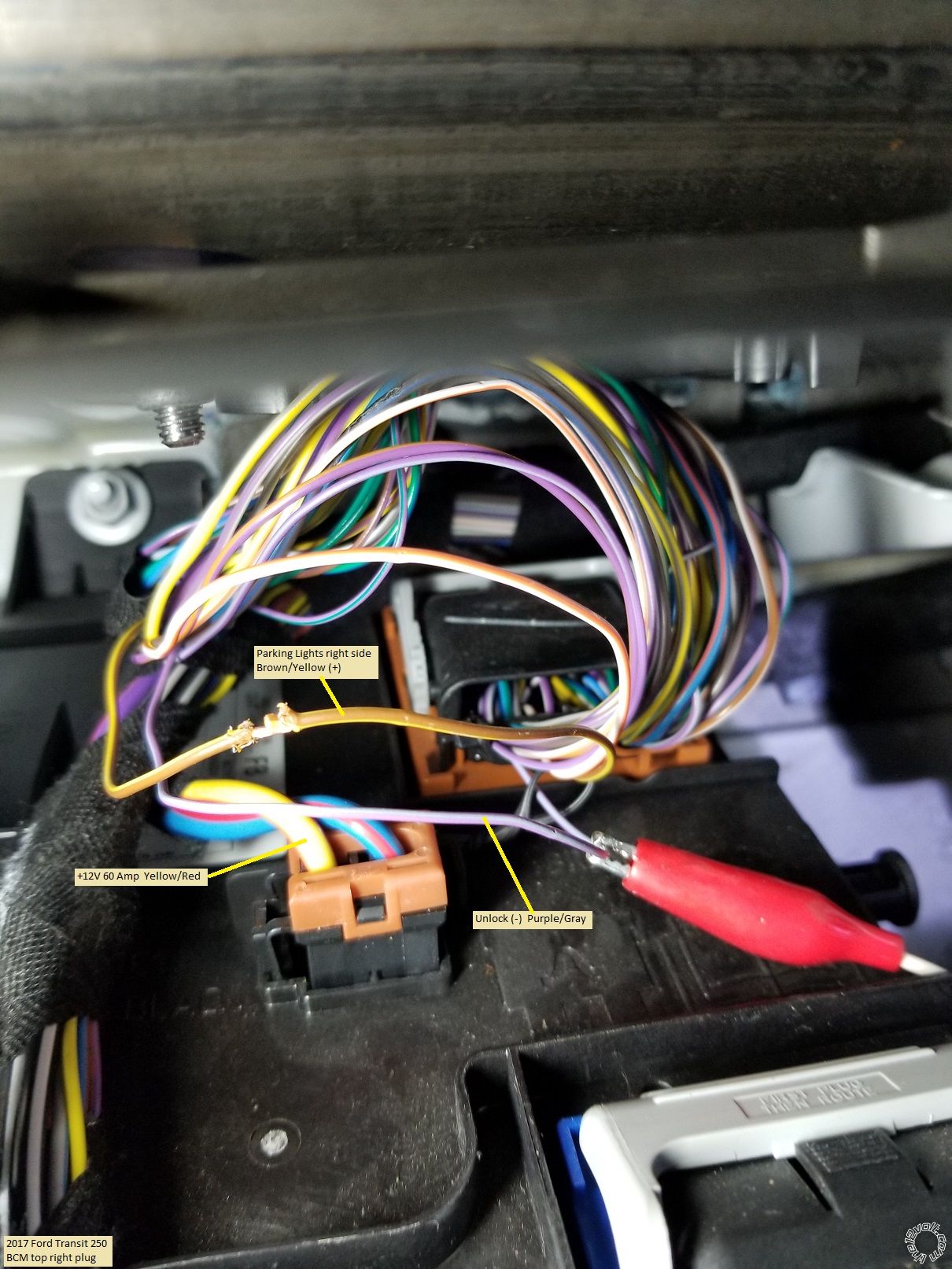
The connector at the upper right has two needed wires.
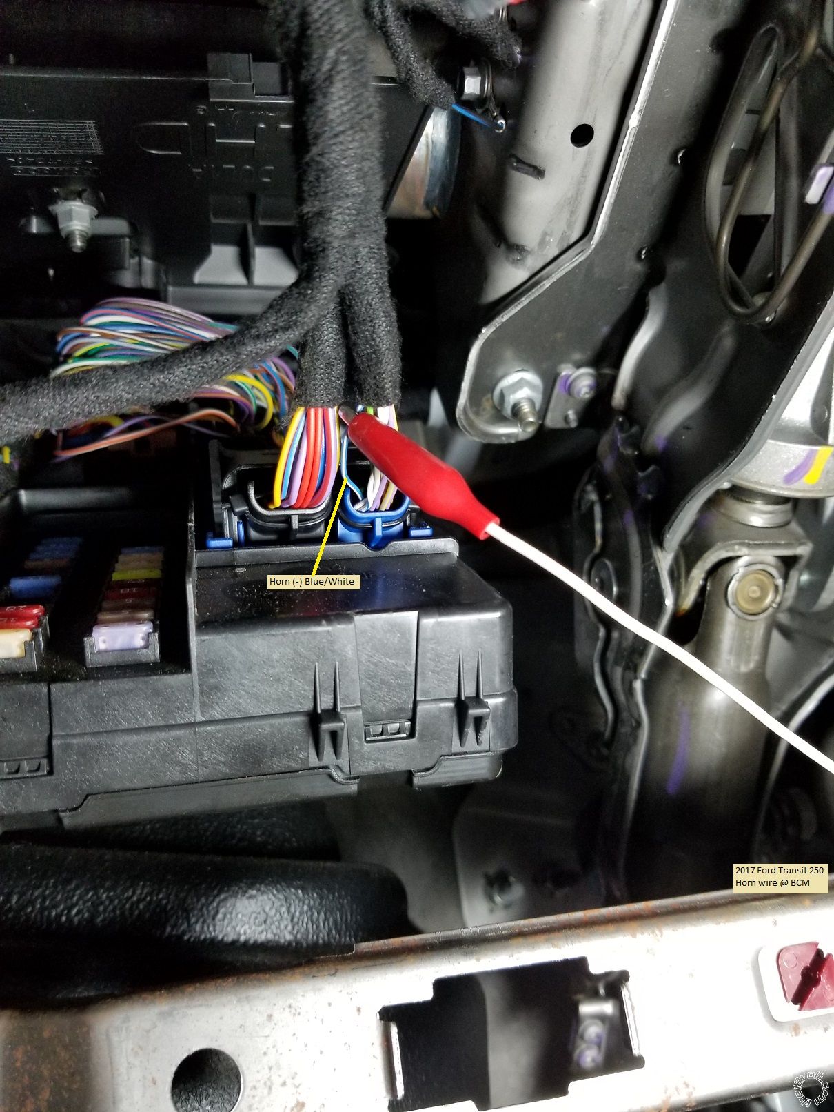
The bottom right plug has the Horn wire ( optional ).
As shown, +12 Volt constant power can be obtained from either wire indicated in the above pictures. With a basic Avital 4115 system and it's low power draw, using the Purple/Red wire is acceptable.
The Brake wire is easiest to obtain at the Brake Pedal switch as shown below :
For the Hood Pin wire, there is a large rubber grommet behind the BCM and strut tower for firewall pass-thru as shown in the following photos.
Besides the 4115 R/S system, you will need two 3 Amp diodes. If you choose not to use the 4115 kit supplied hood pin, a Direct 8613 tilt switch is a good, rust-free choice. Total cost ~ $60.
Below is the necessary wiring if you use an Avital or Viper 4115 R/S system.
H1/1 LIGHT GREEN/BLACK....... FACTORY ALARM DISARM............. not used
H1/2 GREEN/WHITE.................... FACTORY REARM.............................. not used
H1/3 YELLOW............................... (+) IGNITION OUT (TO ALARM)....... not used
H1/4 WHITE/BLUE....................... (-) ACTIVATION INPUT........................not used
H1/5 ORANGE............................... (-) GROUND WHEN LOCKED............ not used
H1/6 BROWN................................ (-) HORN OUTPUT................................. Blue/White @ BCM
H1/7 RED/WHITE......................... (-) TRUNK RELEASE OUTPUT........... not used
H1/8 BLACK.................................. GROUND................................................. Chassis Ground
H1/9 WHITE.................................. (+/-) LIGHT FLASH... set to (+)............. Diode split* to Purple/Green and
...............................................................................................................................Brown/Yellow @ BCM
* The two 3 Amp diodes are necessary to keep the right and left side Parking Lights seperated.
Install the diodes with the bands towards the vehicle wires.
H3/1 BLACK/WHITE............ (-) NEUTRAL SAFETY SWITCH INPUT...... to H1/8 Chassis Ground
H3/2 VIOLET/WHITE.......... TACHOMETER INPUT WIRE........................ not used
H3/3 BROWN......................... (+) BRAKE SWITCH SHUTDOWN WIRE.... Purple/White @ Brake Pedal switch
H3/4 GRAY............................. (-) HOOD PINSWITCH..................................... to Hood Pin switch
H3/5 BLUE/WHITE.............. (-) 200mA 2ND STATUS/REAR DEFOG........... not used
4-pin satellite harness diagram
1 BLUE........... (-) STATUS OUTPUT.............. not used
2 ORANGE.... (-) ACCESSORY OUTPUT..... not used
3 PURPLE..... (-) STARTER OUTPUT........... not used
4 PINK........... (-) IGNITION OUTPUT........... not used
Heavy gauge relay wiring diagram
1 RED...................... (+) (30A) HIGH CURRENT 12 INPUT........... Purple/Red @ BCM fused at 25 Amps
2 PINK/WHITE...... (+) PROGRAMMABLE OUTPUT.................. not used
3 RED...................... (+) (30A) HIGH CURRENT 12V INPUT........ combined with Pin 1 Red
4 ORANGE............. (+) (30 AMP) OUTPUT TO ACC..................... Purple/Green @ Ignition Switch
5 PURPLE.............. (+) (30 AMP) OUTPUT TO STARTER............ Blue/White @ Ignition Switch
6 PINK.................... (+) (30 AMP) OUTPUT TO IGNITION........... Brown/Yellow @ Ignition Switch
Door lock harness, 3-pin connector
1 LIGHT BLUE..... (-) UNLOCK OUTPUT...... Purple/Gray @ BCM
2 EMPTY............... NOT USED
3 GREEN............... (-) LOCK OUTPUT............. not used
There are many good locations to make the Chassis Ground connection
under the dash.
Avital 4115 programming :
Menu 1 Feature 1 to Option 2 ( if you made the horn connection )
Menu 2 Feature 1 to Option 3 ( van has "one-touch" starting )
Menu 2 Feature 4 to Option 3 ( one second Starter output )
Menu 2 Feature 5 to Option 2 ( two button presses to prevent false start-ups )
That should do it. Solder all your connections. Ensure that the tilt / telescopic steering wheel adjustments won't chaff R/S ignition wires. Test everything and put it all back together.
-------------
Soldering is fun!
There are many brands and models or R/S system to choose from. The Avital 4113 / 4115 and the Viper equivalents, Compustar CS801-s and CS910-s and the Prestige APS901E or the newer APS901Z are all excellent low cost 1-way units. For this install I used an Avital 4115. No PATS system means no bypass module, less money and a very simple install.
While this Pictorial includes photos of the lower dash removal, I would recommend that before attempting this install you visit YouTube and do a search on "2015+ transit remote start". There is a 14 minute video posted that shows all the necessary trim panel removal in good detail.
Disassembly :
First pull the trim panel below the steering wheel off.
Next use a trim tool to pop the cup holder up and off.
Use a 7mm socket to remove the three screws shown.
Remove the fuse access panel and then the two 7mm screws indicated.
Release and pull this left side trim piece away from the dash.
To remove the inner brace panel, remove the seven 7mm screws. This is shown in good detail in the previously mentioned video. One screw is on the left side. You must gently lift the center console trim to access one hidden screw at the top right corner on the brace panel.
Remove the two T20 Torx screws indicated at the bottom of the steering column. Then turn the steering wheel to expose plastic releases at the 10 and 2 o'clock positions. Separate the steering column cover halves and remove the bottom piece.
That's it for trim removal. At this point you should verify that there is no black plastic PATS antenna and connector on the ignition switch. Below is a photo of this Transit without the PATS system. If you have the PATS antenna, you will need a bypass module.
Wiring :
Here is a photo of the main Ignition connector removed from the plug with the wires marked. Only 3 connections are needed, IGN, ACC and Starter.
Below is a photo of the vans BCM located to the left of the steering column.
The lower left connector has the left side Parking Light wire as shown.
The connector at the upper right has two needed wires.
The bottom right plug has the Horn wire ( optional ).
As shown, +12 Volt constant power can be obtained from either wire indicated in the above pictures. With a basic Avital 4115 system and it's low power draw, using the Purple/Red wire is acceptable.
The Brake wire is easiest to obtain at the Brake Pedal switch as shown below :
For the Hood Pin wire, there is a large rubber grommet behind the BCM and strut tower for firewall pass-thru as shown in the following photos.
Besides the 4115 R/S system, you will need two 3 Amp diodes. If you choose not to use the 4115 kit supplied hood pin, a Direct 8613 tilt switch is a good, rust-free choice. Total cost ~ $60.
Below is the necessary wiring if you use an Avital or Viper 4115 R/S system.
H1/1 LIGHT GREEN/BLACK....... FACTORY ALARM DISARM............. not used
H1/2 GREEN/WHITE.................... FACTORY REARM.............................. not used
H1/3 YELLOW............................... (+) IGNITION OUT (TO ALARM)....... not used
H1/4 WHITE/BLUE....................... (-) ACTIVATION INPUT........................not used
H1/5 ORANGE............................... (-) GROUND WHEN LOCKED............ not used
H1/6 BROWN................................ (-) HORN OUTPUT................................. Blue/White @ BCM
H1/7 RED/WHITE......................... (-) TRUNK RELEASE OUTPUT........... not used
H1/8 BLACK.................................. GROUND................................................. Chassis Ground
H1/9 WHITE.................................. (+/-) LIGHT FLASH... set to (+)............. Diode split* to Purple/Green and
...............................................................................................................................Brown/Yellow @ BCM
* The two 3 Amp diodes are necessary to keep the right and left side Parking Lights seperated.
Install the diodes with the bands towards the vehicle wires.
H3/1 BLACK/WHITE............ (-) NEUTRAL SAFETY SWITCH INPUT...... to H1/8 Chassis Ground
H3/2 VIOLET/WHITE.......... TACHOMETER INPUT WIRE........................ not used
H3/3 BROWN......................... (+) BRAKE SWITCH SHUTDOWN WIRE.... Purple/White @ Brake Pedal switch
H3/4 GRAY............................. (-) HOOD PINSWITCH..................................... to Hood Pin switch
H3/5 BLUE/WHITE.............. (-) 200mA 2ND STATUS/REAR DEFOG........... not used
4-pin satellite harness diagram
1 BLUE........... (-) STATUS OUTPUT.............. not used
2 ORANGE.... (-) ACCESSORY OUTPUT..... not used
3 PURPLE..... (-) STARTER OUTPUT........... not used
4 PINK........... (-) IGNITION OUTPUT........... not used
Heavy gauge relay wiring diagram
1 RED...................... (+) (30A) HIGH CURRENT 12 INPUT........... Purple/Red @ BCM fused at 25 Amps
2 PINK/WHITE...... (+) PROGRAMMABLE OUTPUT.................. not used
3 RED...................... (+) (30A) HIGH CURRENT 12V INPUT........ combined with Pin 1 Red
4 ORANGE............. (+) (30 AMP) OUTPUT TO ACC..................... Purple/Green @ Ignition Switch
5 PURPLE.............. (+) (30 AMP) OUTPUT TO STARTER............ Blue/White @ Ignition Switch
6 PINK.................... (+) (30 AMP) OUTPUT TO IGNITION........... Brown/Yellow @ Ignition Switch
Door lock harness, 3-pin connector
1 LIGHT BLUE..... (-) UNLOCK OUTPUT...... Purple/Gray @ BCM
2 EMPTY............... NOT USED
3 GREEN............... (-) LOCK OUTPUT............. not used
There are many good locations to make the Chassis Ground connection
under the dash.
Avital 4115 programming :
Menu 1 Feature 1 to Option 2 ( if you made the horn connection )
Menu 2 Feature 1 to Option 3 ( van has "one-touch" starting )
Menu 2 Feature 4 to Option 3 ( one second Starter output )
Menu 2 Feature 5 to Option 2 ( two button presses to prevent false start-ups )
That should do it. Solder all your connections. Ensure that the tilt / telescopic steering wheel adjustments won't chaff R/S ignition wires. Test everything and put it all back together.
-------------
Soldering is fun!
Replies:
Posted By: mustyk@att.net
Date Posted: February 03, 2019 at 7:57 AM
I have done hundreds of these vans because I work at a company that does fleets of Transits, Promaster Vans, Transit connects, and Promaster City"s. I can do a complete alarm/remote start combo from the BCM ONLY and don't have to access the steering column. I have attached a copy of the wiring diagram that I wrote and sent in to the "Tech Tips (misc.)" category of your uploads. *Note: the door triggers differ in wiring if its a "swing door" or "sliding door"2019 FORD TRANSIT VAN
-------------
thetopinstaller
-------------
thetopinstaller
Posted By: mustyk@att.net
Date Posted: February 03, 2019 at 8:02 AM
If you would like to contact me about this install please use the following address: tigershock3@gmail.com
-------------
thetopinstaller
-------------
thetopinstaller
Posted By: kreg357
Date Posted: February 08, 2019 at 7:25 AM
Excellent info. :star: That wire chart is a great addition and covers a good bit more than the "basic" install above. Doing everything at the BCM can save time and keep things neater. Thanks!
-------------
Soldering is fun!
-------------
Soldering is fun!
Posted By: jburbano
Date Posted: March 14, 2019 at 7:21 PM
Do you need a bypass if your van has no PATS option installed? Mine does not.
Posted By: kreg357
Date Posted: March 15, 2019 at 8:33 AM
If your Transit is like the one pictured about without a PATS antenna ring on the ignition switch you do not need a bypass module. Being as the Factory Remotes work while the engine is running under a remote start-up, a simple one button R/S system is all you need. While I made the R/S to vehicle Unlock wire connection, it is optional.
-------------
Soldering is fun!
-------------
Soldering is fun!
Posted By: jburbano
Date Posted: March 15, 2019 at 11:30 AM
Thanks for the reply!! I was doing a LOT more reading last night and came to the same conclusion on PATS. However, my intent is to install an alarm/starter which I already have. So that means I need to figure out a bit more w/o a bypass. It is more complicated but the Fortin bypass I bought apparently comes with no support. The dealer and Fortin refuse to answer questions, so I would really like to return it. I did get a reply from Ken who uploaded the wiring sheet. That was VERY helpful, but I am not understanding some of the references. This has been the most helpful thread I have found! I will add to it when I get everything figured out. Waiting for another reply from Ken now.
Posted By: kreg357
Date Posted: March 16, 2019 at 8:32 AM
Yes, that is the problem with most Remote Start and bypass module manufacturers, they do not want to provide Tech Support to end users. Probably because of the large learning curve for the 12 Volt installer.
With no PATS3 system, most of the reason for the bypass module is gone. The EVO-ALL programming only shows the steps required for a vehicle equipped with PATS. While I'm sure there is a way to program the EVO-ALL to the Transit without utilizing the transponder bypass function, it is not shown in the guide. The EVO-ALL would be helpful for your install in that it can supply the Door Status, Brake signal and a Tach signal. Obtaining the Door Status for your aftermarket alarm system will be your biggest hurdle. The (-) N.C. door triggers are a PITA. The ADS AL-CA bypass module flashed with DL FM-3 firmware can be used and programmed to a non-PATS equipped Transit and would provide the Door Status signal for the aftermarket alarm system.
Use this tech guide to properly interface the door triggers to the alarm system :
https://www.wiresheet.com/v3/diagrams200/243%20-%20Normally%20Closed%20Door%20Trigger%20Circuit.pdf Directed has TechTip 1097 that supplies the same info. Here is that link : https://www.the12volt.com/installbay/file.asp?ID=1139 You will need 1N4001 diodes, some 10k ohm resistors and a fuse holder w/ 5 Amp fuse.
-------------
Soldering is fun!
Posted By: jburbano
Date Posted: March 16, 2019 at 11:13 AM
kreg357 Thanks for that info!!! I will do some research on the ADS. Cutting all of the door wires as shown in the guides is not my first choice. But that interface is also half the cost of the Fortin/harness. Unfortunately, my alarm has a Fortin data interface which simplifies wiring. It also has discrete wires so at least I have options.
Posted By: kreg357
Date Posted: March 16, 2019 at 11:40 AM
The ADS AL-CA is a great module. You would need to find a seller that would flash the correct firmware ( DL FM-3 ) on it prior to shipment. The ADS AL-CA can be flashed to support either ADS or DBI D2D communications. Not sure exactly what Brand and Model R/S Alarm system you are installing. Even if you went W2W between the R/S and the ADS AL-CA, it isn't that many wires and can be neatly done on the bench prior to actual vehicle installation.
Here is a link to the ADS AL-CA bypass module with DL FM-3 firmware install guide : https://images.idatalink.com/corporate/Content/Manuals/DL-FM3/ADS-AL(DL)-FM3-EN_20190314.pdf
-------------
Soldering is fun!
Here is a link to the ADS AL-CA bypass module with DL FM-3 firmware install guide : https://images.idatalink.com/corporate/Content/Manuals/DL-FM3/ADS-AL(DL)-FM3-EN_20190314.pdf
-------------
Soldering is fun!
Posted By: jburbano
Date Posted: March 16, 2019 at 11:43 AM
Well bummer. According to this https://www.idatalink.com/search/search?vehicle_make_id=12&vehicle_year_id=2017&vehicle_model_id=1030&vehicle_id=23786
The ADS is not what I need. If you look at the features list, it will not arm/disarm the factory alarm and is missing some other required features. I am going to look at the other models.
The ADS is not what I need. If you look at the features list, it will not arm/disarm the factory alarm and is missing some other required features. I am going to look at the other models.
Posted By: kreg357
Date Posted: March 16, 2019 at 2:55 PM
If your Transit does not have the PATS system, does it have the Ford Factory Alarm system? The one in this Pictorial had neither. ( The Panic button on the Factory Key FOB is not indicative of an alarm system.)
The list of supported features shown on that ADS comparison page could be a little misleading. The complete system units like the HC series do support more features because they are shown in the install guide and are manual hardwire connections not listed with the ADS AL-CA bypass only module install guide.
There is another way to monitor the door triggers without an ADS AL-CA or the diodes and resistor circuits previously mentioned. For a mere $22 you can get an Omega AU-NCT module from eBay. Here is a link to the install guide : https://www.wiresheet.com/v3/install_guides/Accessories/AU-NCT.pdf
-------------
Soldering is fun!
Posted By: jburbano
Date Posted: March 16, 2019 at 3:28 PM
Well that is a good question. I have been trying to figure that out. As near as I can tell no. My test was to use the factory keyfob to lock the van and then open the door through the inside handle. On other vehicles, that was a sure way to set off the factory alarm. On this one, nothing.
Posted By: kreg357
Date Posted: March 16, 2019 at 3:46 PM
Yep, good chance you don't have the Factory Alarm. You can try setting the alarm a couple of different ways. Hit Lock twice on the FOB with all the doors closed, then wait a few minutes, then open a door from the inside. You could hit the inner door lock button while the door is open, then close the door, wait a few minutes. Then open a door with the inner handle.
-------------
Soldering is fun!
-------------
Soldering is fun!
Posted By: jburbano
Date Posted: March 16, 2019 at 10:34 PM
Well I am close to getting the remote start working w/o the bypass. Unfortunately, it is doing some odd stuff like starting and then turning off after 2-3 seconds. It will do this 3 times before failing and giving an error. It's as if the remote start can't tell the engine started ok. I have determined that I do have one touch start in the van. Since I have no tach wire, I set it for voltage sense start. The one wire I have not been able to determine how to properly connect is the keysense wire. Based on the original post, I thought it was not required. Any thoughts?
Posted By: kreg357
Date Posted: March 17, 2019 at 2:13 AM
Some Ford's delay alternator output for a bit after engine start up and this causes a R/S's Voltage or Tachless monitoring to be unreliable. If your R/S system has a Hybrid or Fixed Crank setting, that would be the way to go. That's what I used on the Viper 4115 system in this Pictorial as mentioned in the R/S programming changes listed in the post.
For most Fords, Keysense is not required. I did not power this wire and no issues were encountered. Test the Keysense wire with the ignition key. It should be a (+) signal. If that is the case, you can use the R/S's unused IGN2 (+) output to power the wire during a R/S to see if that makes any difference.
-------------
Soldering is fun!
Posted By: jburbano
Date Posted: March 20, 2019 at 10:44 PM
Well most of my trouble turned out to be the old, but unused, Zenesis alarm/start. Zenesis is junk. Swapping it for a Crimestopper got me working. I did end up ordering and using the Omega AU-NCT. That was a great suggestion!! The only bump was that the right sliding door is different then all of the other doors. It grounds when open which is the opposite of all other doors. Thanks Ford! A couple of diodes solved that problem. Doing this w/o a bypass requires a LOT of hard wiring and time, but it was a good learning experience. Since the BCM re-uses the same wire colors, it is even more difficult. I am not sure I could have figured it out w/o the full Ford wiring manual. That allowed me to distinguish wires by color and gauge. Since both of the bypasses I looked at required about half of this hard wiring anyway, I am not sure what the best choice is. It seems crazy that existing bypasses cant't 'bypass' the need for parking light and lock hard wires. Those do go to the BCM afterall.
Posted By: mustyk@att.net
Date Posted: March 21, 2019 at 6:19 AM
TO: jburbano
If you look in the downloads section I sent in ALL the wiring diagram/colors necessary to do the transit Van. It even includes the AU-NCT wiring note that the Sliding door is negative triggered and the "Swing" door is -(N.C.). I tried to send it in MY format but this is how it came thru (see below). If you want a more readable version you can go to the xdowmload section and I beleive its in the misc section.
FULL SIZE VAN
12volts
YELLOW/RED (8ga) + @BCM (large 2 pin conn )
Ignition 1
BN/YE + @BCM Blue 76 conn pin 76 or ign harness
Starter 1
(not for starter kill) BU/WH + @BCM Blue76 conn pin 71 or ign harness
Starter 1
(for starter kill) BU/WH + In harness to LT of column (thickest of the 3)
Accessory 1
VT/GN + @BCM Blue 76 conn pin 75 or ign harness
Keysense BU/GY + ignition harness
BCM IS LOCATED LH SIDE OF DASH
Motor-Lock all
VT/GN Pin 18 @BCM BROWN 46 pin conn
Motor-Unlock Driver
BU/BN Pin 39 @BCM Brown 46 pin conn
Motor-Unlock All
BU/GN Pin 45 @BCM Brown 46 pin conn
Power Lock
GY/YE - Pin 25 @BCM BROWN 76 pin conn
Power Unlock
VT/GY - Pin 56 @BCM BROWN 76 pin conn
LF Parking Light +
GN/OR*
GN/RD** + Pin 14 @BCM Brown 46 pin conn
RF Parking Light +
BN/YE + Pin 66 @BCM Brown 76 pin conn
LR Parking Light +
VT/GN + Pin 15 @BCM Brown46 pin conn
RR Parking Light +
WH/OR + Pin 67 @BCM Brown 76 pin conn
SJB: SMART JUNCTION BOX IS LOCATED ABOVE DRVRS LT FOOT *2015 & 2018 **2016-2017
TX YE/OR data PATS con pin3
RX VT/GY data PATS con pin4
IGNITION YE/VT + PATS con pin1
GROUND - PATS con pin2
LF Door Trigger
GN/VT Open/N.C. Pin 44 @BCM BROWN 76 pin conn
RF Door Trigger
WH Open/N.C. Pin 34 @BCM BROWN 76 pin conn
Left Side Cargo Door GN Open/N.C. Pin 35 @BCM BROWN 76 pin conn
Right Side Cargo Door YE^^ Open/N.C.^ Pin 51 @BCM BROWN 76 pin conn
Hood Pin
WH/BN Open/N.C. Pin 40 @BCM BROWN 76 pin conn
Rear Cargo Door
BN/VT Open/N.C. Pin 50 @BCM BROWN 76 pin conn
^for swing door ^^(-)for slider door
Factory Alarm Disarm
Disarms with factory remote unlock
Reverse Light
GN/BN + Pin 11 @BCM Brown 46 pin conn
Brake Wire
VT/WH + @ Switch or Pin58 @BCM BROWN 76 pin conn
Front Dome Lights YE/GY - Pin 2 @BCM Brown 46 pin conn
Rear Dome Lights WH/BU - Pin 1 @BCM Brown 46 pin conn
Horn Trigger
BU/WH - Pin 17 @BCM BLUE 76 pin conn
Interface Module:
Immobilizer Bypass Combo-Unit
Part #: OL-MDB-ALL with TB-FM3 firmware
Alternate Part1 #: PASS-4
Alternate Part2 #: EVO-ALL 71.00
Notes: Accessories Needed: Quad diodes kit for Parking lights. Dual Reverse diodes for Dome Lights. Note# 243 for normally closed door trigger circuit(10k ohm resistors)
AU-NCT needed for Door triggers
TO: jburbano
-------------
thetopinstaller
Posted By: ace_boy2099
Date Posted: December 20, 2020 at 6:05 PM
I noticed the O.P. said the pictorial was done on a 250 cargo van, are the wire colors and such the same for the 150 passenger Vans too? I may be getting a 17 transit 150soon and am contemplating a r/s and or alarm in it.
I know in the plans are trailer hitch and 7-way witing (eTrailer), cruise control (rostra 250-9636), and auto lights (directed 545t). For the cruise and auto lights I'll have to figure out the wiring.
O.P. thanks for the write up, I'll have to look up that video for the dash panels.
I know in the plans are trailer hitch and 7-way witing (eTrailer), cruise control (rostra 250-9636), and auto lights (directed 545t). For the cruise and auto lights I'll have to figure out the wiring.
O.P. thanks for the write up, I'll have to look up that video for the dash panels.
Posted By: kreg357
Date Posted: December 22, 2020 at 6:48 AM
From all of the wire list sources, it appears they all have only one group for the full size Transit. From that I would think that the 150, 250 and the 350 are all the same with some vehicles not equipped with the transponder based immobilizer system and the door pin differences. Hopefully Mustyk will provide additional info from all his experience. Good luck with your new van!
-------------
Soldering is fun!
-------------
Soldering is fun!
Posted By: ace_boy2099
Date Posted: December 24, 2020 at 9:15 PM
I'm not sure if I should start a new topic or just ask here, Since it's fitting here I'll just ask here.
I see mentioned about using 3A diodes to separate the Parking light wires (since Fords geniuses decided to split them), What diodes were used? I have some 1n4001 (I think that's the number, I didn't look before asking this) but i believe they are 1 amp, What's the number for the 3amp ones? Is it the 1N5401?
I'm actually asking for the Directed Nite-Lite 545T Module install, So I'll probably need 2 for parking lights and 2 for headlights since it appears they are also separated.
Since I didn't find one when I searched the almighty Google I probably should do a write-up on how-to install it, But I'm fairly sure I'm just gonna try and get it done since I have limited time available to do things.
Posted By: kreg357
Date Posted: December 25, 2020 at 6:27 AM
The 1N540x series are the correct 3 Amp diodes. I usually get 1N5401's figuring that there never should be any pulses over 100 volts on these type of circuits.
You could even use the 6A10 6 Amp diodes. The price is sometimes less and the extra current capability won't hurt anything. They are a bit bigger in diameter so larger heatshrink tube is needed.
-------------
Soldering is fun!
You could even use the 6A10 6 Amp diodes. The price is sometimes less and the extra current capability won't hurt anything. They are a bit bigger in diameter so larger heatshrink tube is needed.
-------------
Soldering is fun!
Posted By: mustyk@att.net
Date Posted: December 25, 2020 at 7:43 AM
ace_boy_2099:
After posting that wiring diagram I didn't include the size of diode used, I am so used to just grabbing the ones I always use for that vehicle. They are 1N5406 and carry at least 3 amps which is more than enough to be safe. I got mine from "Micro Alarm" company out of California . You can also use: 1N5822.
-------------
thetopinstaller
Posted By: ace_boy2099
Date Posted: December 26, 2020 at 7:18 PM
Today I spent half the day looking for which wires do what on my new to me 2017 Ford Transit 150, (I also discovered that there's no pats ring on mine) and found some discrepancies from the chart posted in the wiring diagram page (Listed under 2015 I believe). I don't know if anyone else has discovered this or not but I will share what I found.
I started with a Multi-Meter but then switched to my Power Probe III, easier to understand/read in my opinion. A "Short Cut" I did while testing with the power probe is once I found one of the wires I was looking for by Probing each one with the headlight switch turned on, when I found a wire that was hot I turned the switch off to verify the correct functioning, after I verified it was the correct wire I back-fed it with the power probe with the switch off to see which side it belonged to, same thing with the parking lights.
First the BCM/Fuse panel referenced for the wires has 4 plugs on it, molded into the casing body by the connectors it has "C1 Black", "C2 Brown", "C3 Brown", & "C4 Blue" and the diagram page only has "plug B" and "Plug C" which is inaccurate and for me confusing to try and decipher.
Second the category for Headlight on it is actually the high beams (It does have the note for that by the wires but it should be on it's own line not under headlights.
The actual Headlight wires (on my application/vehicle) were C2-Blue/Green (Right side/Passengers), and C3-Brown/Blue (Left side/Drivers)
when I tested the parking lights I discovered that C2-Green/Orange was both the drivers (Left) Front AND Rear, and C3-Brown/Yellow was both Passengers (right) Front AND Rear. I didn't think to test the turn signal switch once I found those wires to see if it was the turn signal wires or the park wires, but my dad said it was the running lights when I back-fed them and he looked, but I doubt he would have mistaken that.
and as for the Wipers that was C3-White. I don't recall the operation, I think it was powered while off and grounded when activated, But don't quote me on that.
If I recall correctly the parking lights and headlights read ground until power was applied to turn them on (I know the head lights (low beams) did, I made note of it). I don't remember how the high beams acted.
I did not go and double check the whole diagram on the site for accuracy but I did for the wires I was looking for. Now that I have more of an idea of where what wires are, after I get the rest of what I need, I can go in and try to install everything at once, in-fact I'm thinking of adding a remote start kit from 12volt solutions (or Compustar CM7000) to the mix too. However If one of you guys (Musty / Kreg) want to come down to Florida and do it for me, I won't object... lol, I've about had it just trying to find the wires, I'm dreading having to go in and connect to all those TINY wires in that confined space.
Edit:
I was looking at the install instructions for the Compustar CM7000 and I see in the options there's an option to turn off the security features, I'm sure it's dumb to get it and only install half of it just for remote start when I could just get the 7300 (I think, Maybe it's the 7200, Either way...)unit instead. Question on this is what all would I HAVE to hook up just to have the remote start work using the factory Keyfob (hooked to the horn wire, I forget what they call it "Trigger Input" I think), or should I just bite the bullet and do the whole alarm and starter then in the future it's just a simple option change to have the full system going? and should I get the AL Blade (Bypass, but not used as a bypass) thing for the doors and such or would this unit handle them, I'd seen a note about using PIC wires for the N.C. Wires in place of diodes and relays and such towards the end of the booklet...
Posted By: kreg357
Date Posted: December 27, 2020 at 10:49 AM
Just a tip / personal preference on my part. Considering how thin gauge the wires are in the newer vehicles, I purchased a used Teledyne StripAll Model TWC-1. New units go for $400 plus but used ones can be found for under $100. They use a pair of heated blades to melt through the wire insulation without cutting or even nicking the stranded wires. While they are meant to remove the insulation from a cut end of wire, they can be used in the middle of a length of wire. You will notice the bunched insulation on the stripped wires in this pictorial. There is an adjustable thermostat to set the blade temperature. This comes in handy for the different types of insulation material ( plastic, rubber, Teflon, etc ). The only downside is the length of the stripper arms and the width of the body. Getting in to tight places is not impossible but does take patience. Picture below :
-------------
Soldering is fun!
-------------
Soldering is fun!
Posted By: mustyk@att.net
Date Posted: December 30, 2020 at 6:03 AM
To: Ace_boy:
First of all you will not find a parking light wire at the headlight switch. It is a low level data bus line that is neither (+) or (-). This is why you must got to each and every one of the Parking light outputs to the bulbs (4). Secondly there are some variances to the parking light wires, I have them indicated with a star in my chart (downloads section of this site) .Example LF prkg LT wire is Green/Orange for 2015 and 2018, but may be Green/Red for 2016-2017. There may be some variances even to that. If the wire harness company ran out of Green/Orange they may have substituted Green/Red. This chart may not be Gospel but its pretty darn accurate considering I have done hundreds of these vans and this is what I have encountered. See the downloads section I have sent a couple of updated wiring Diagram charts. My wiring diagrams are color coded charts. Good Luck!
-------------
thetopinstaller
Posted By: ace_boy2099
Date Posted: December 30, 2020 at 7:00 AM
Yeah, I noticed the headlight switch only has 4 wires so I figured that was a bust. I tested ALL of the wires in the 2 brown connectors (C2 and C3 According to the molded BCM, again not checking for all functions just the ones I was looking for at the time; Now that I decided to add a CM7000 to the mix I will have to go through again to verify the wires I didn't do the first time around. Maybe Mines made somewhat special, I don't know, I'm just reporting what I found on my vehicle and how I found it. also a little update, we figured out through a VIN decoder (on one of the ford forums, FTE i think it was, that the van is actually a Transit 350, not the 150 we originally thought. Probably doesn't matter but hey, It's worth mentioning.
Posted By: ace_boy2099
Date Posted: January 06, 2021 at 3:42 PM
Our of curiosity, how would I tell if I can use the low power option on the cm7000, and if I can do I need the low power cn1, or just the cn 3 I think it is? I'm sure itd be alot easier to connect thin to thin than thin to thick wires.