2020 Kia Soul, Regular Key, Remote Start Pictorial
Printed From: the12volt.comForum Name: Car Security and Convenience - Alarm/Remote Start Pictorials
Forum Discription: Installer submitted Alarm, Keyless Entry, and Remote Start Pictorials from our Car Security and Convenience forum.
URL: https://www.the12volt.com/installbay/forum_posts.asp?tid=146665
Printed Date: May 23, 2026 at 9:34 PM
Topic: 2020 Kia Soul, Regular Key, Remote Start Pictorial
Posted By: kreg357
Subject: 2020 Kia Soul, Regular Key, Remote Start Pictorial
Date Posted: January 09, 2021 at 6:16 AM
This is a basic Remote Start with Keyless Entry install on a third generation KIA Soul which covers the 2020 through 2021 model years. It might cover all regular key third gen Souls going to 2024...
This vehicle was a 2020 KIA Soul with regular key ignition system. This vehicle had Auto Trans and the Factory Alarm system with Hood pin. Being a U.S. market vehicle, it DID NOT have a transponder based immobilizer system.
Notes on aftermarket system selected. On regular key vehicles the factory remote keyless entry system in inoperative during R/S engine run time. As such, a 4 button system was used to allow lock functions while the engine is remote started. Due to the factory alarm system and that the power locks go to sleep 30 seconds after vehicle is locked, a bypass module was used rather than making the additional wire connections and to save some install time. While there are many systems that meet the vehicle needs, a Compustar CS925-s unit with a Blade AL bypass module was chosen. The Blade-AL bypass module handles the alarm and locks plus provide a Tach signal and the Hood Pin input. A total of 11 wire connections is all that is needed for this install ( or 12 if ACC2 is powered ). Below is a photo of the CM900-s with Blade-AL after bench prep.
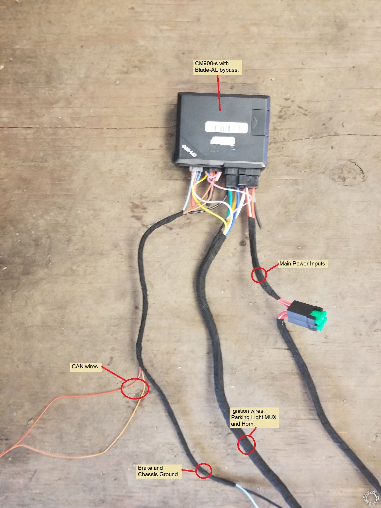
As shown in the Bench Prep photo, power for the R/S system was obtained from the fuse box and not at the main ignition switch harness. This is strictly an installer preference. There are two perfectly good +12V constant wires at the ignition switch but due to the limited access area and the tilt/telescopic steering wheel, I usually get power at the fuse box.
Disassembly :
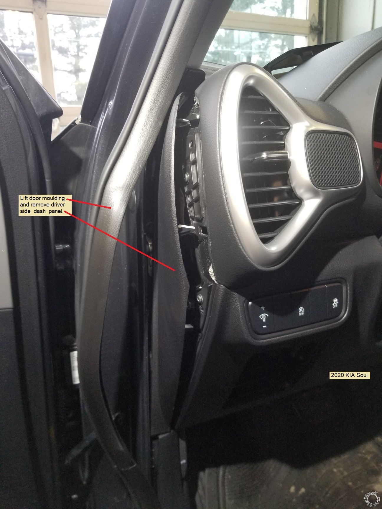
Lift the door molding along the drivers dash pillar. Remove the driver side dash panel with a non-marring trim tool. This will expose two Philips screws, allow antenna harness routing to the upper windshield and access to a good chassis ground location.
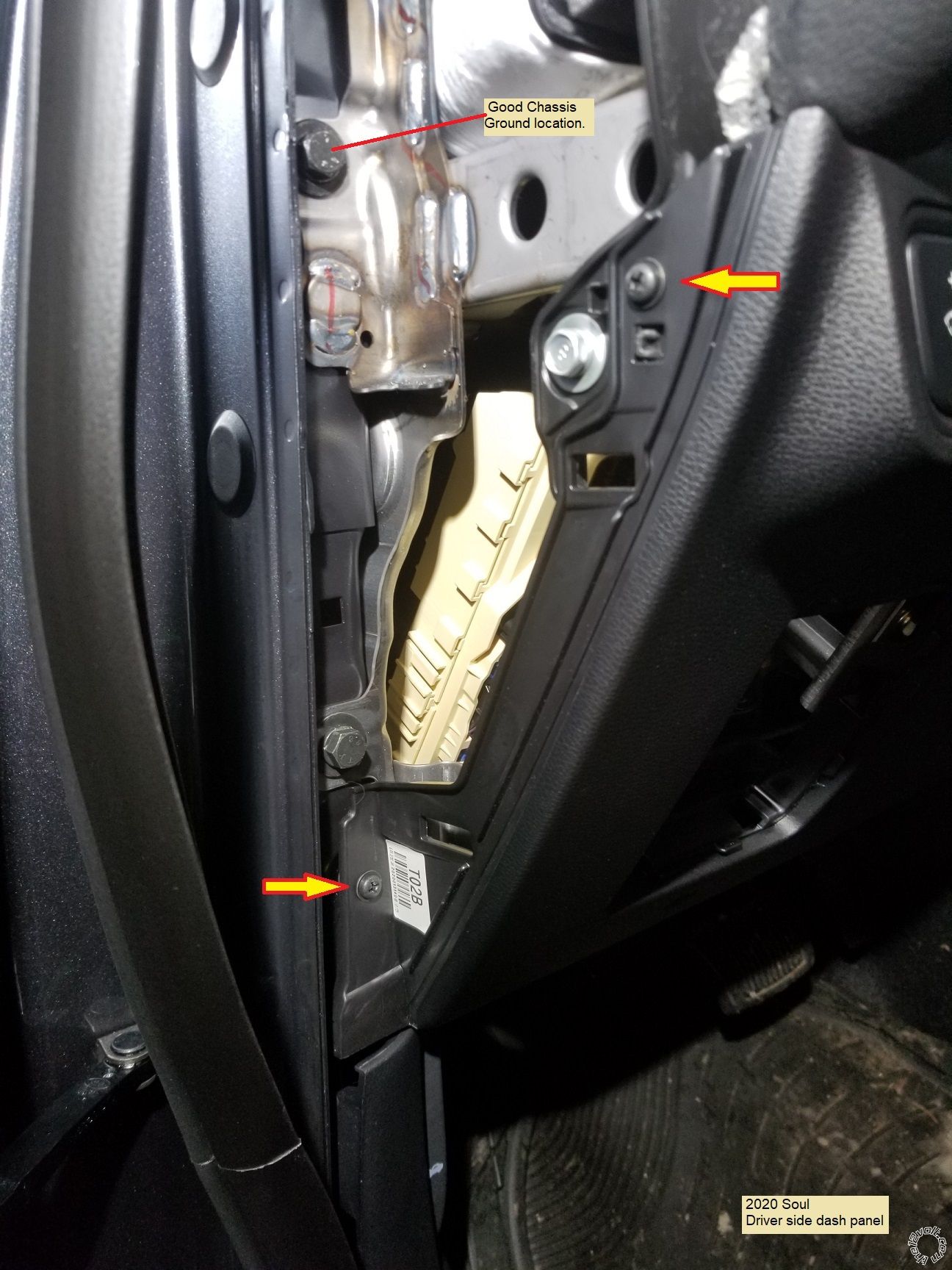
Remove the two Phillips screws indicated in the photo below.
Next remove the lower dash panel Philips screw indicated below.
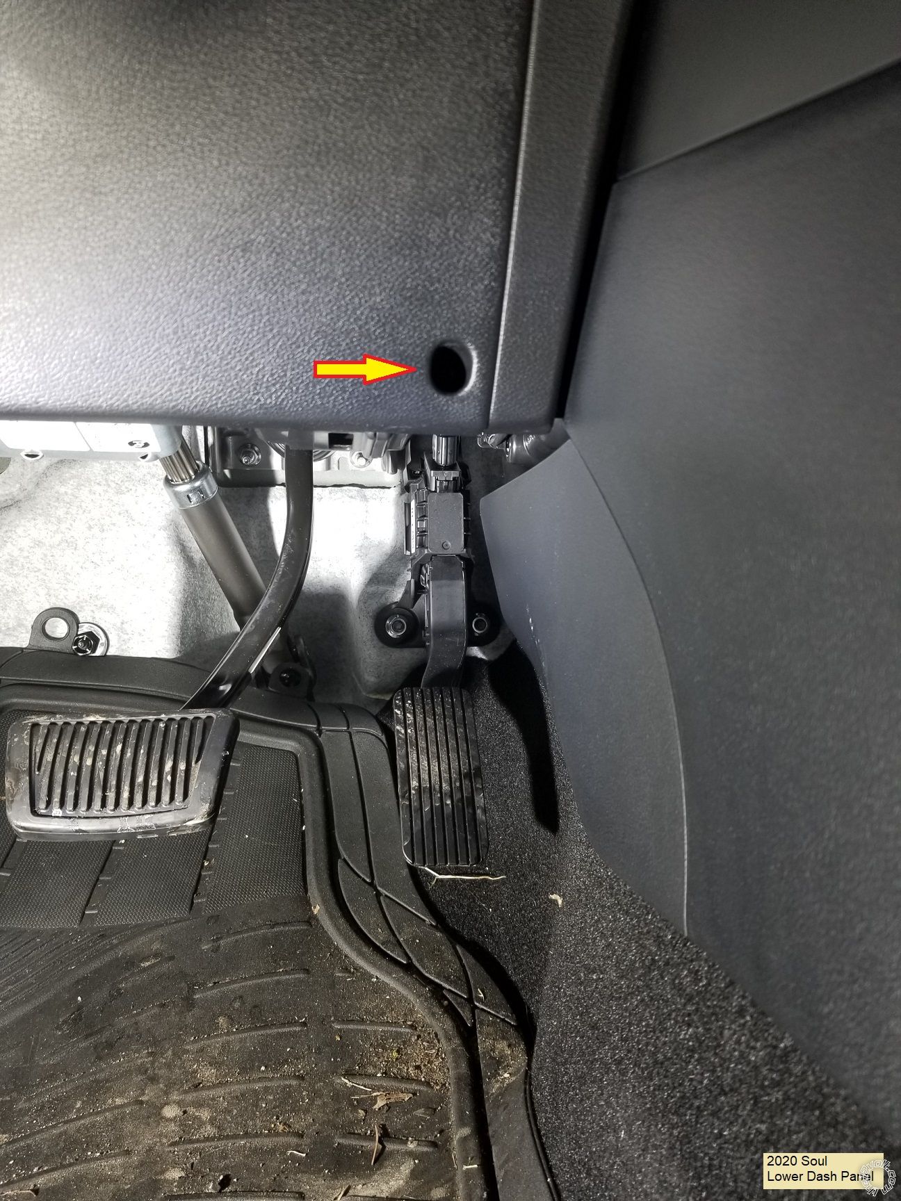
Release the lower dash panel at the door side and remove the panel. Pop the OBD2 connector out of the panel and unplug the other attached harnesses. Place the panel to one side.
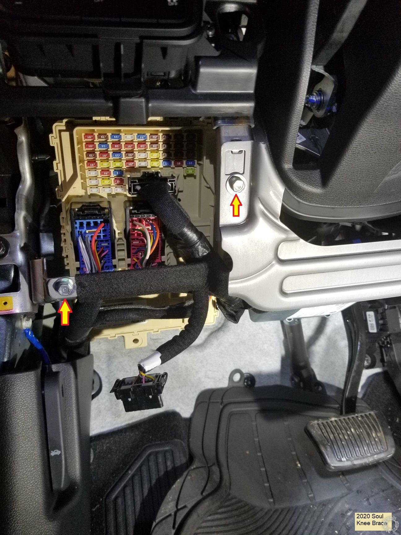
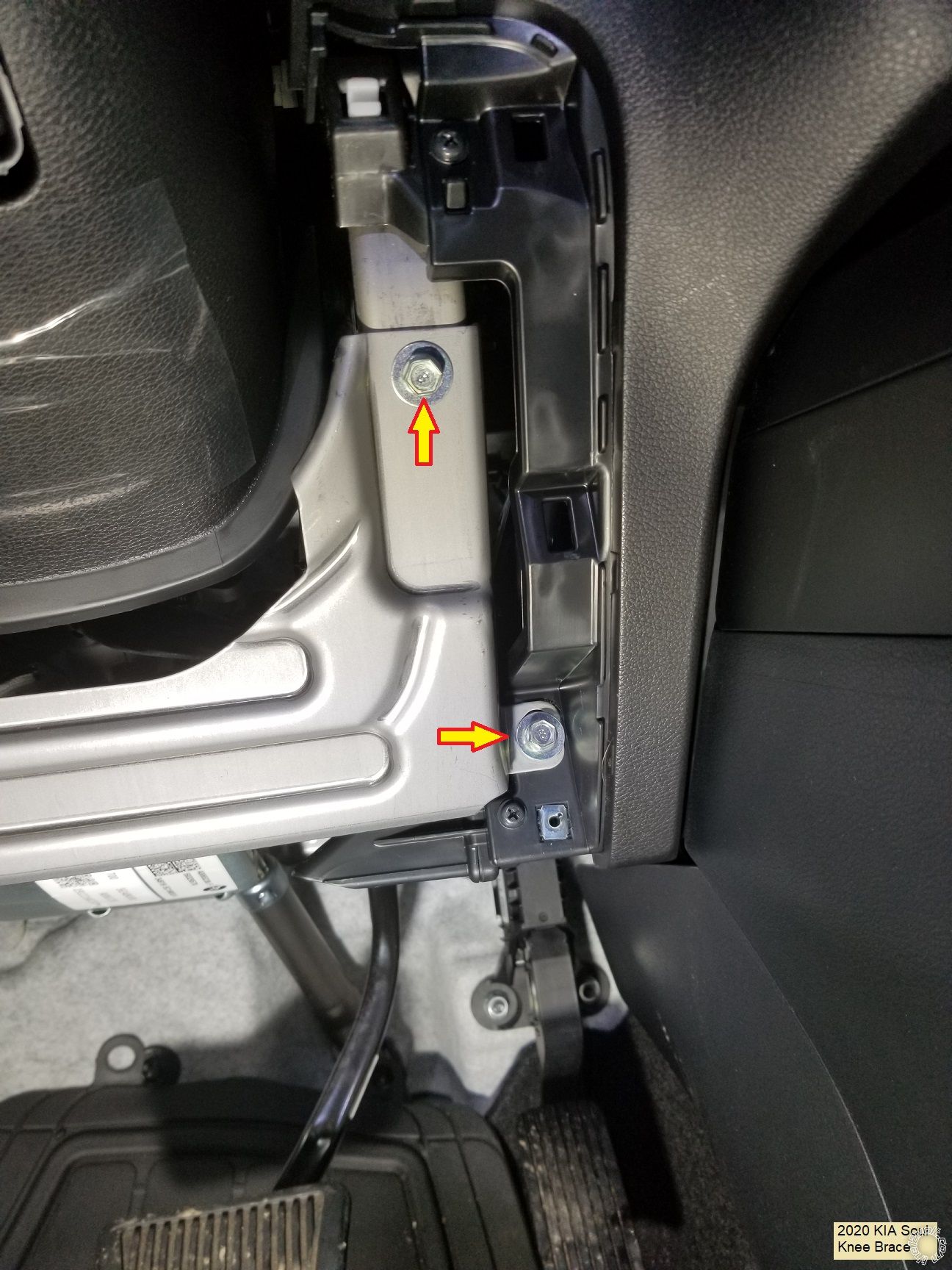
Remove the four 10mm bolts from the knee brace and remove to provide better access to the fuse box.
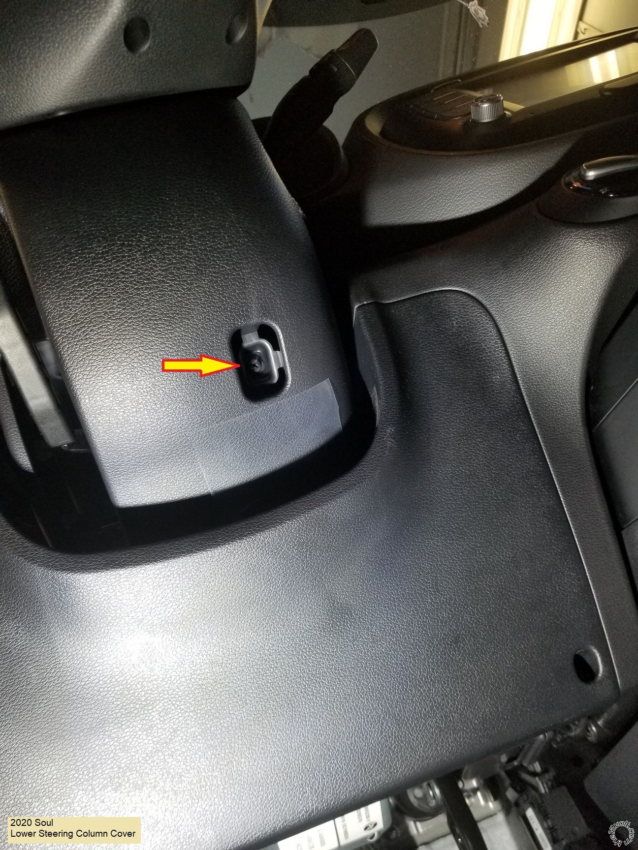
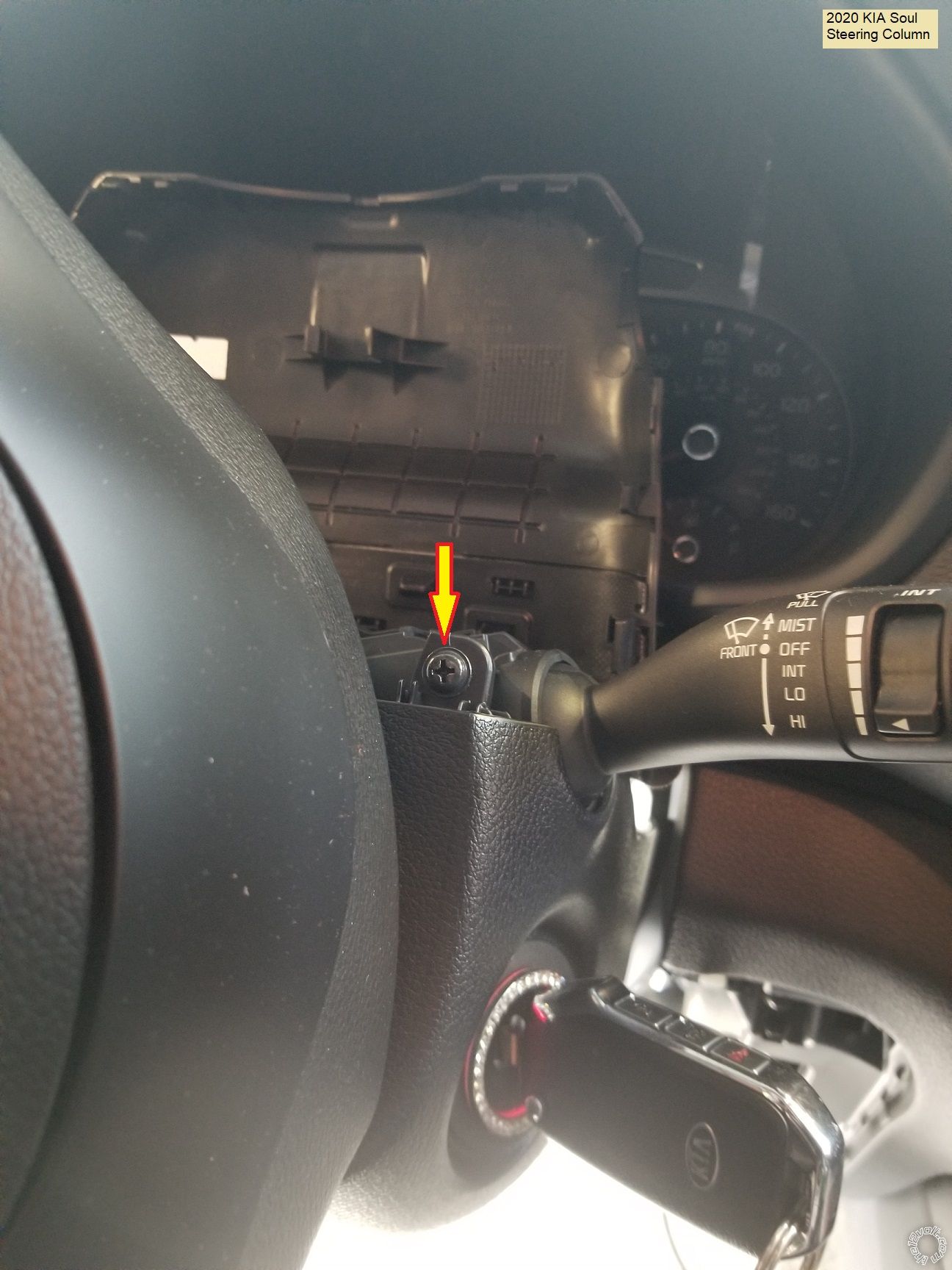
Remove the Phillips screw from the lower steering column trim.
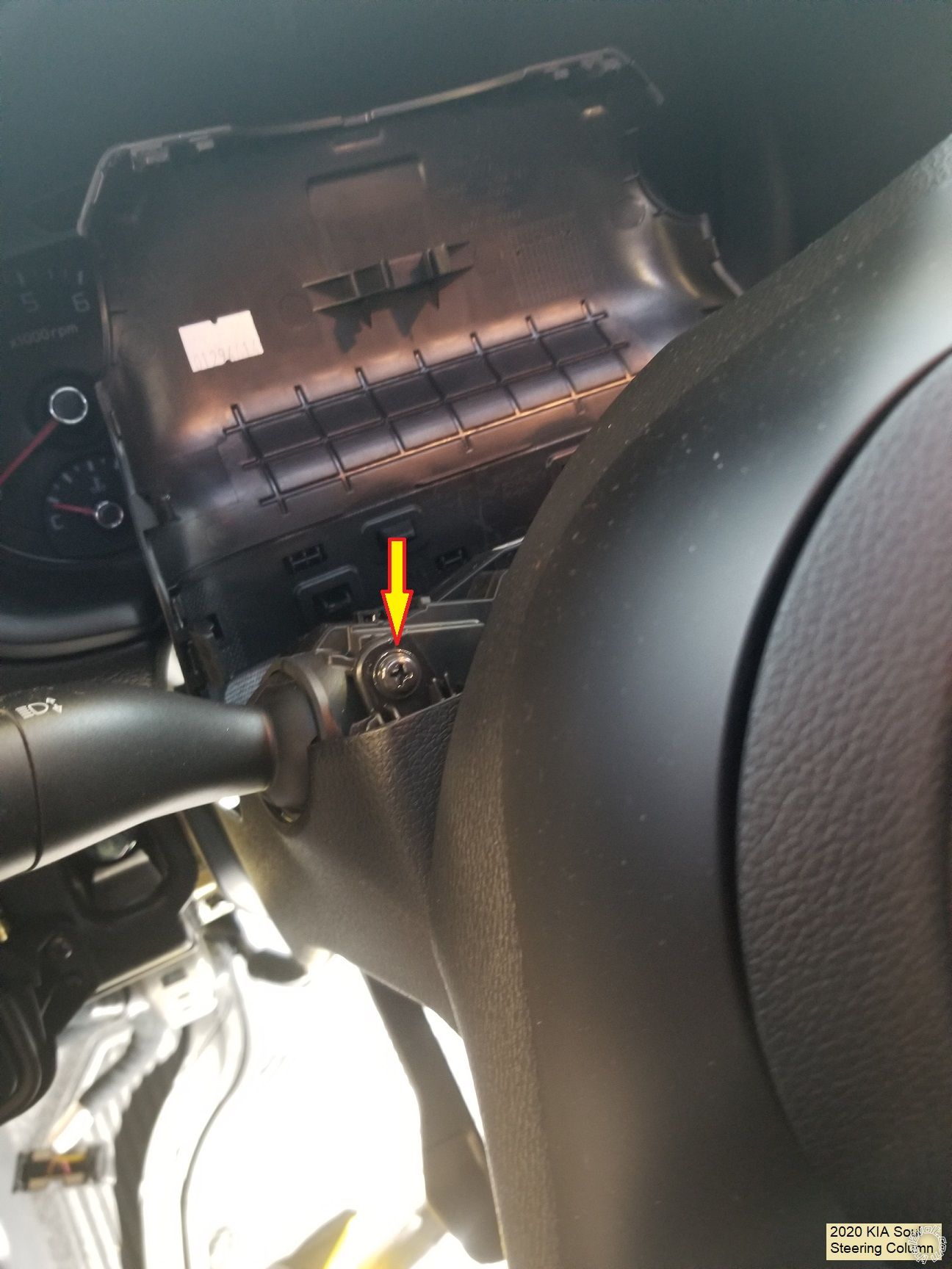
Use a non-marring trim tool to separate the upper steering column trim and tilt it up to expose two Phillips screws that retain the lower column trim panel. Remove these two Phillips screws and the lower trim piece.
Wire connections :
As mentioned above, I went to the main fuse box for +12V constant power. Below is a photo of the four +12V constant power wires. There are 4 available, use any two.
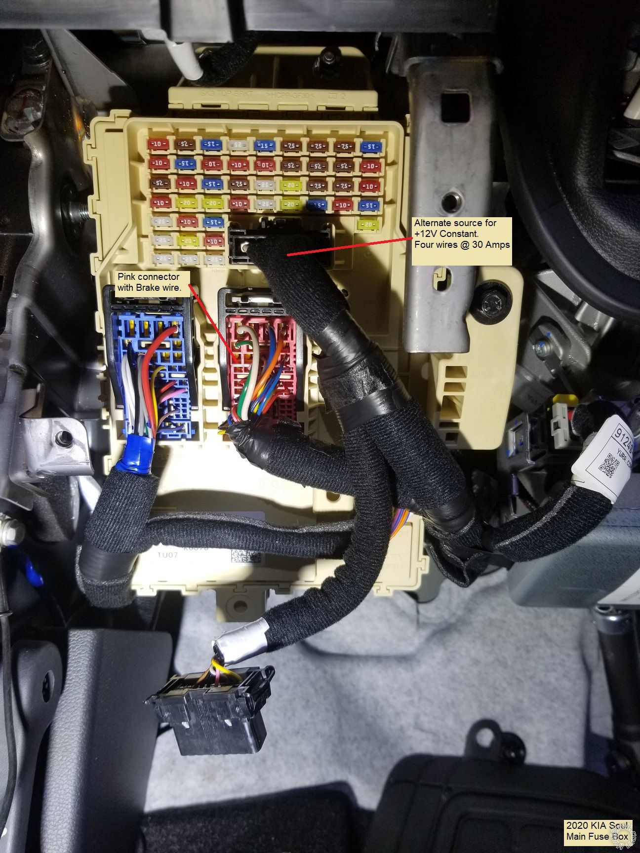
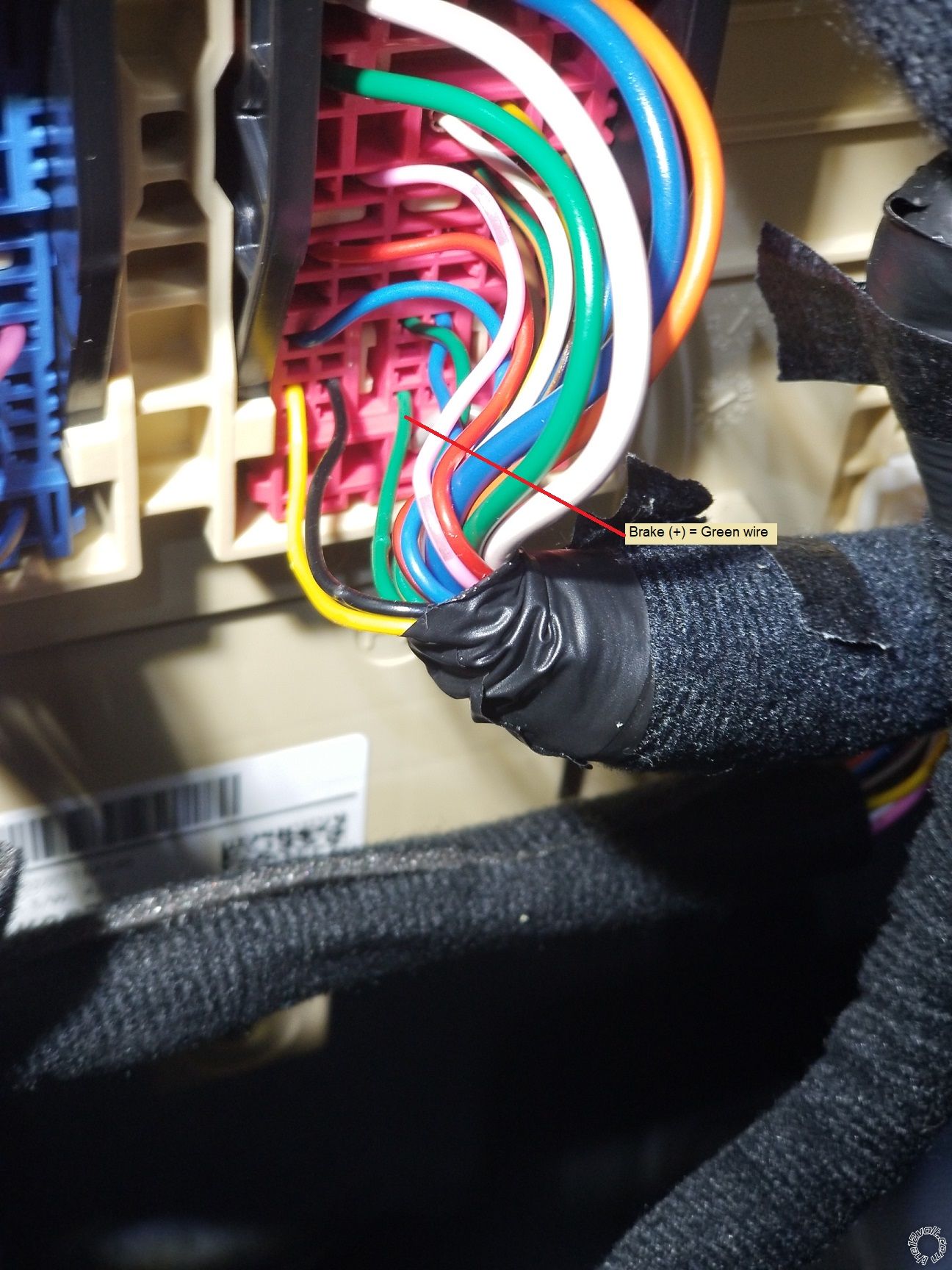
This vehicle did not have a transponder immobilizer system. The iDatalink install guide suggests using the Brake wire found near the transponder wire in the Driver Kick Panel but rather than remove more trim and run a longer wire, I used the Brake wire at the fuse box as shown below.
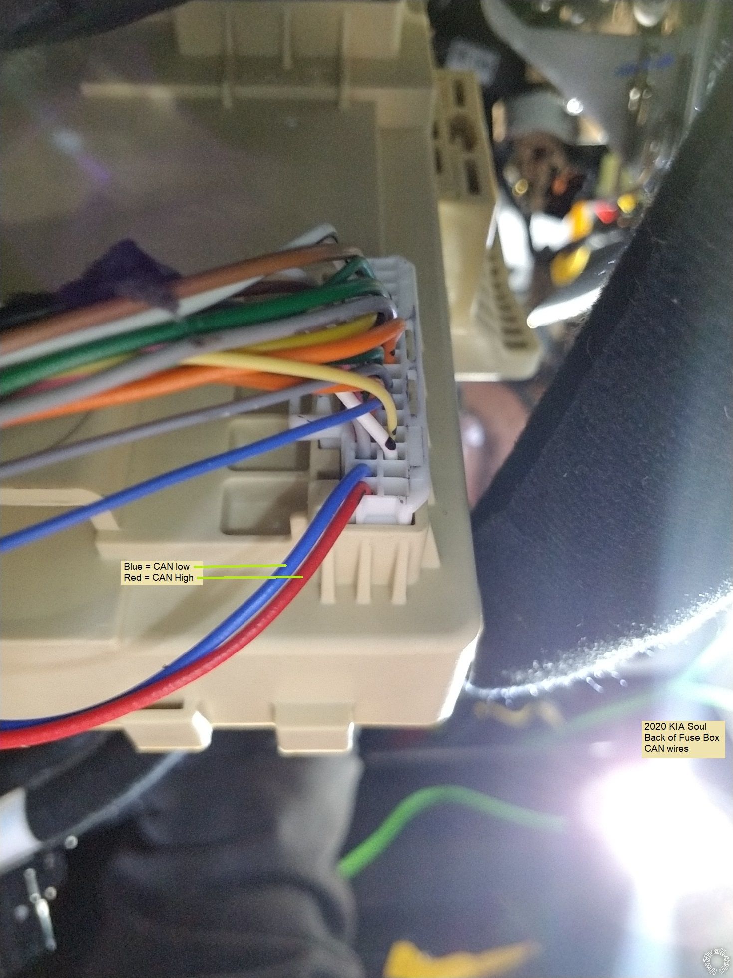
The vehicle CAN wires are found in the bottom connector at the back of the fuse box. While you could dismount the fuse box for easier access, I just went under the fuse box, exposed the two wires and made the connections.
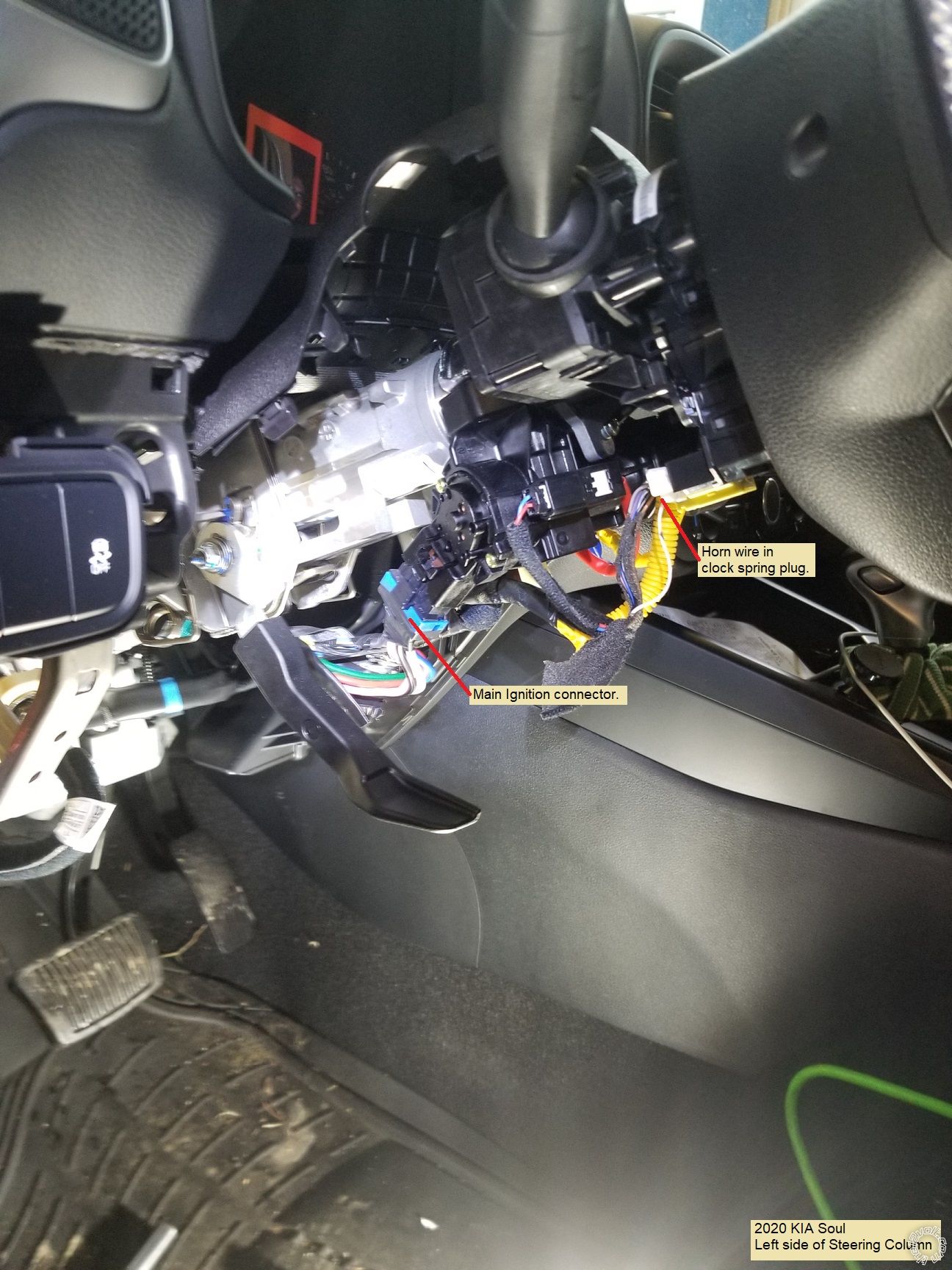
In the steering column are the remaining wires. This is a picture of the left side of the steering column with the horn and ignition wire locations marked.
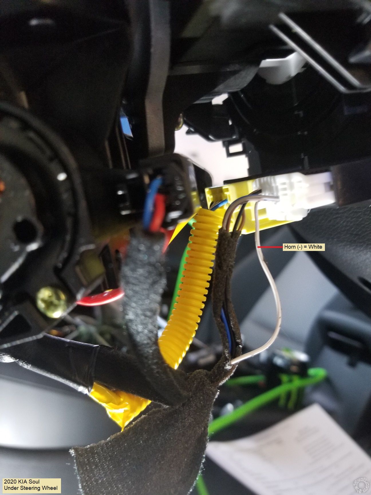
Next is a close up of the horn wire :
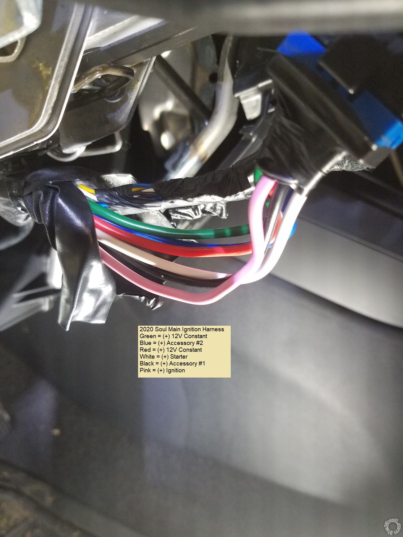
Here is shot of the ignition wires.
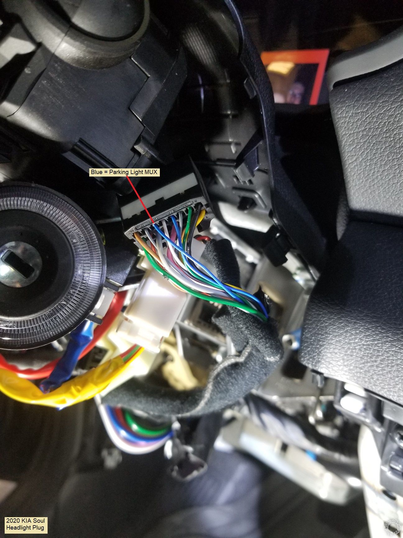
At the right side of the steering column is the Headlight Switch connector. Photo below :
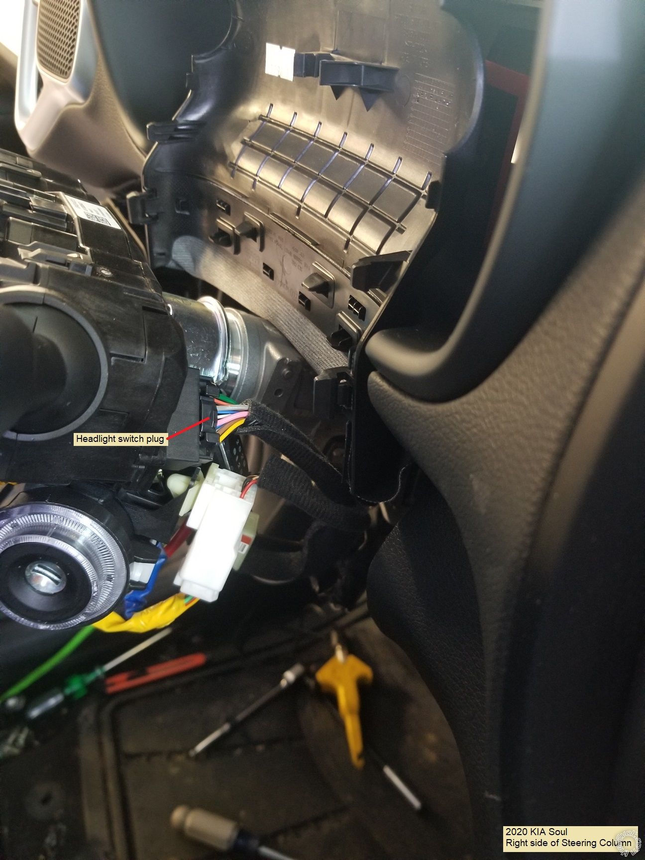
Standard installs require a 1680 ohm resistor on the (-) Parking Light output wire. The Blade-AL produces this signal so no external resistor is needed. Shown below is the Headlight connector unplugged and the Parking Light MUX wire :
Make the Chassis Ground wire connection with a soldered on terminal ring to clean, paint and rust free solid metal.
That's about it. Install the two 30 amp fuses and program the bypass module. Program the CM900-s to Engine Sensing = Tach, 2-10 Opt 2, and perform the Tach Learn process. Test everything, mount the CM900-s securely behind the fuse box and re-assemble the dash.
For the DIYer there are several online sellers that sell the Compustar system and will perform the necessary firmware flash on the Blade-AL bypass module. Depending on your needs, systems like the CS925-s and CS4900-s are solid basic R/S w/RKE units. Here is a wire listing for the CM900-s w/Blade-AL to 2020 KIA Soul. The Blade-AL must be flashed with the BLADE-AL(DL)-HK13 firmware.
CN1
Pin 1 Red - Constant 12V_______________________________Red at fuse box
Pin 2 Green/White - Programmable Output________________not used
Pin 3 Red/White - Constant 12V_________________________Blue at fuse box
Pin 4 White - Accessory 12V positive (+)_______________Black @ Ignition Switch Harness
Pin 5 Blue - Programmable Output_______________________Optional - set jumper to ACC - Blue @ Ignition Switch Harness
Pin 6 Yellow - Starter 12V positive (+)________________White @ Ignition Switch Harness
Pin 7 Green - Ignition 12V positive (+)________________Pink @ Ignition Switch Harness ( also Pink from Blade Harness )
Pin 8 Black - Ground negative (-) input________________Chassis Ground
CN3
Pin 1 Green/White - (fixed) Parking light 250mA negative (-) output_________________________not used - handled by Blade AL output
Pin 2 Blue/Lt. Green - [POC 2] Lock 250mA, 800mS (-) negative output________________________not used - handled by Blade AL via CAN
Pin 3 Blue - [POC 3] Unlock 250mA, 800mS (-) negative output________________________________not used - handled by Blade AL via CAN
Pin 4 Black - [POC 4] Status/Ground while running (GWR) 250mA latched negative (-) output______not used
Pin 5 Orange - [POC 5] Factory Alarm Arm (FAA) 250mA, 800mS negative (-) output_____________not used - handled by Blade AL via CAN
Pin 6 Orange/White - [POC 6] Factory Alarm Disarm (FAD) 250mA, 800mS negative (-) outpu_______not used - handled by Blade AL via CAN
Pin 7 White - [POC 7] Horn:250mA negative (-) output________________________________________White @ clock spring connector
Pin 8 Gray/Black - Hood Pin negative (-) (default setting) input____________________________not used - handled by Blade AL via CAN
Pin 9 Light Blue/White - Brake 12V positive (+) input_______________________________________Green at fuse box Pink connector
Pin 10 RED/White - Trigger start (-) input__________________________________________________not used
Pin 11 RED - Positive (+) input_____________________________________________________________not used
Pin 12 Yellow/Black - Engine sensing input (A/C)____________________________________________not used - handled by Blade AL via CAN
CN2 Blade-AL harness
WHITE/BLACK - DATA VEHICLE SIDE________________not used - U.S market vehicle without transponder
WHITE/RED - DATA CONNECTOR SIDE________________not used - U.S market vehicle without transponder
YELLOW - PARKING LIGHT (MUX) OUTPUT_____________to Blue at Headlight Switch plug
BROWN/RED - CANH_______________________________to Red at back of fuse box
BROWN/YELLOW - CANL____________________________to Blue at back of fuse box
PINK - IGNITION (+) INPUT________________________to CM900-s CN1 Pin 7 Green
GRAY/RED - DATA CONNECTOR SIDE_________________not used - U.S market vehicle without transponder
Bonus wire :
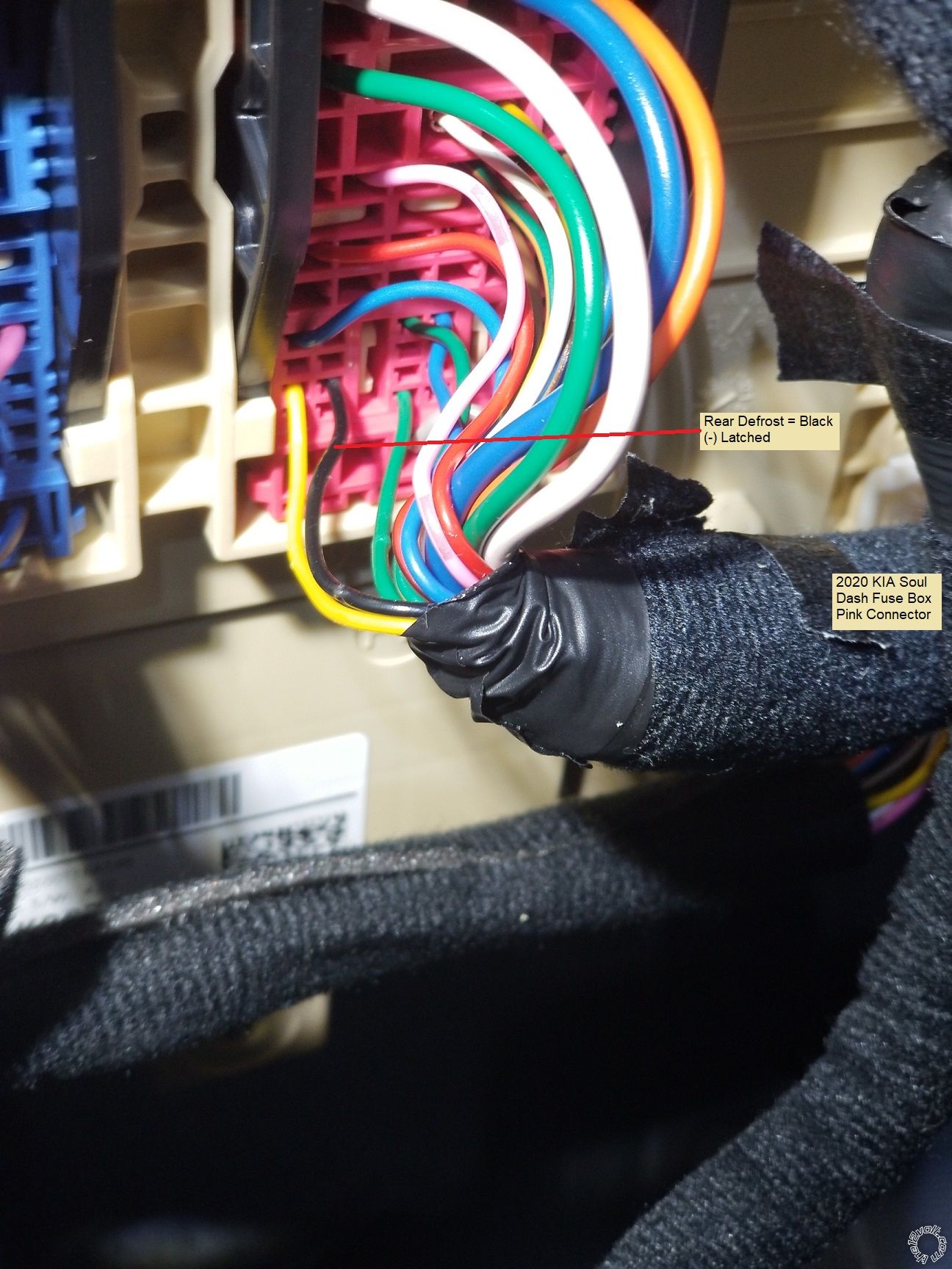
With the CM900-s and the OP-500 Programmer, you can reassign one of the unused POC wires in CN3 to Rear Defrost ( Value 17 ) and set 3-17 to Option 3 for a 7 minute latched output starting a few seconds after a Remote Startup. If you wanted to get extra fancy, you could get a Compustar FT-TEMP SENSOR THERMISTOR, plug it into the CM900-s port CN7 and set 3-13 to Option 2 or 3. This will turn on the rear defroster only if the temperature is below the set temp during a R/S.
-------------
Soldering is fun!
This vehicle was a 2020 KIA Soul with regular key ignition system. This vehicle had Auto Trans and the Factory Alarm system with Hood pin. Being a U.S. market vehicle, it DID NOT have a transponder based immobilizer system.
Notes on aftermarket system selected. On regular key vehicles the factory remote keyless entry system in inoperative during R/S engine run time. As such, a 4 button system was used to allow lock functions while the engine is remote started. Due to the factory alarm system and that the power locks go to sleep 30 seconds after vehicle is locked, a bypass module was used rather than making the additional wire connections and to save some install time. While there are many systems that meet the vehicle needs, a Compustar CS925-s unit with a Blade AL bypass module was chosen. The Blade-AL bypass module handles the alarm and locks plus provide a Tach signal and the Hood Pin input. A total of 11 wire connections is all that is needed for this install ( or 12 if ACC2 is powered ). Below is a photo of the CM900-s with Blade-AL after bench prep.
As shown in the Bench Prep photo, power for the R/S system was obtained from the fuse box and not at the main ignition switch harness. This is strictly an installer preference. There are two perfectly good +12V constant wires at the ignition switch but due to the limited access area and the tilt/telescopic steering wheel, I usually get power at the fuse box.
Disassembly :
Lift the door molding along the drivers dash pillar. Remove the driver side dash panel with a non-marring trim tool. This will expose two Philips screws, allow antenna harness routing to the upper windshield and access to a good chassis ground location.
Remove the two Phillips screws indicated in the photo below.
Next remove the lower dash panel Philips screw indicated below.
Release the lower dash panel at the door side and remove the panel. Pop the OBD2 connector out of the panel and unplug the other attached harnesses. Place the panel to one side.
Remove the four 10mm bolts from the knee brace and remove to provide better access to the fuse box.
Remove the Phillips screw from the lower steering column trim.
Use a non-marring trim tool to separate the upper steering column trim and tilt it up to expose two Phillips screws that retain the lower column trim panel. Remove these two Phillips screws and the lower trim piece.
Wire connections :
As mentioned above, I went to the main fuse box for +12V constant power. Below is a photo of the four +12V constant power wires. There are 4 available, use any two.
This vehicle did not have a transponder immobilizer system. The iDatalink install guide suggests using the Brake wire found near the transponder wire in the Driver Kick Panel but rather than remove more trim and run a longer wire, I used the Brake wire at the fuse box as shown below.
The vehicle CAN wires are found in the bottom connector at the back of the fuse box. While you could dismount the fuse box for easier access, I just went under the fuse box, exposed the two wires and made the connections.
In the steering column are the remaining wires. This is a picture of the left side of the steering column with the horn and ignition wire locations marked.
Next is a close up of the horn wire :
Here is shot of the ignition wires.
At the right side of the steering column is the Headlight Switch connector. Photo below :
Standard installs require a 1680 ohm resistor on the (-) Parking Light output wire. The Blade-AL produces this signal so no external resistor is needed. Shown below is the Headlight connector unplugged and the Parking Light MUX wire :
Make the Chassis Ground wire connection with a soldered on terminal ring to clean, paint and rust free solid metal.
That's about it. Install the two 30 amp fuses and program the bypass module. Program the CM900-s to Engine Sensing = Tach, 2-10 Opt 2, and perform the Tach Learn process. Test everything, mount the CM900-s securely behind the fuse box and re-assemble the dash.
For the DIYer there are several online sellers that sell the Compustar system and will perform the necessary firmware flash on the Blade-AL bypass module. Depending on your needs, systems like the CS925-s and CS4900-s are solid basic R/S w/RKE units. Here is a wire listing for the CM900-s w/Blade-AL to 2020 KIA Soul. The Blade-AL must be flashed with the BLADE-AL(DL)-HK13 firmware.
CN1
Pin 1 Red - Constant 12V_______________________________Red at fuse box
Pin 2 Green/White - Programmable Output________________not used
Pin 3 Red/White - Constant 12V_________________________Blue at fuse box
Pin 4 White - Accessory 12V positive (+)_______________Black @ Ignition Switch Harness
Pin 5 Blue - Programmable Output_______________________Optional - set jumper to ACC - Blue @ Ignition Switch Harness
Pin 6 Yellow - Starter 12V positive (+)________________White @ Ignition Switch Harness
Pin 7 Green - Ignition 12V positive (+)________________Pink @ Ignition Switch Harness ( also Pink from Blade Harness )
Pin 8 Black - Ground negative (-) input________________Chassis Ground
CN3
Pin 1 Green/White - (fixed) Parking light 250mA negative (-) output_________________________not used - handled by Blade AL output
Pin 2 Blue/Lt. Green - [POC 2] Lock 250mA, 800mS (-) negative output________________________not used - handled by Blade AL via CAN
Pin 3 Blue - [POC 3] Unlock 250mA, 800mS (-) negative output________________________________not used - handled by Blade AL via CAN
Pin 4 Black - [POC 4] Status/Ground while running (GWR) 250mA latched negative (-) output______not used
Pin 5 Orange - [POC 5] Factory Alarm Arm (FAA) 250mA, 800mS negative (-) output_____________not used - handled by Blade AL via CAN
Pin 6 Orange/White - [POC 6] Factory Alarm Disarm (FAD) 250mA, 800mS negative (-) outpu_______not used - handled by Blade AL via CAN
Pin 7 White - [POC 7] Horn:250mA negative (-) output________________________________________White @ clock spring connector
Pin 8 Gray/Black - Hood Pin negative (-) (default setting) input____________________________not used - handled by Blade AL via CAN
Pin 9 Light Blue/White - Brake 12V positive (+) input_______________________________________Green at fuse box Pink connector
Pin 10 RED/White - Trigger start (-) input__________________________________________________not used
Pin 11 RED - Positive (+) input_____________________________________________________________not used
Pin 12 Yellow/Black - Engine sensing input (A/C)____________________________________________not used - handled by Blade AL via CAN
CN2 Blade-AL harness
WHITE/BLACK - DATA VEHICLE SIDE________________not used - U.S market vehicle without transponder
WHITE/RED - DATA CONNECTOR SIDE________________not used - U.S market vehicle without transponder
YELLOW - PARKING LIGHT (MUX) OUTPUT_____________to Blue at Headlight Switch plug
BROWN/RED - CANH_______________________________to Red at back of fuse box
BROWN/YELLOW - CANL____________________________to Blue at back of fuse box
PINK - IGNITION (+) INPUT________________________to CM900-s CN1 Pin 7 Green
GRAY/RED - DATA CONNECTOR SIDE_________________not used - U.S market vehicle without transponder
Bonus wire :
With the CM900-s and the OP-500 Programmer, you can reassign one of the unused POC wires in CN3 to Rear Defrost ( Value 17 ) and set 3-17 to Option 3 for a 7 minute latched output starting a few seconds after a Remote Startup. If you wanted to get extra fancy, you could get a Compustar FT-TEMP SENSOR THERMISTOR, plug it into the CM900-s port CN7 and set 3-13 to Option 2 or 3. This will turn on the rear defroster only if the temperature is below the set temp during a R/S.
-------------
Soldering is fun!
Replies:
Posted By: ftb_soup
Date Posted: October 18, 2024 at 6:05 PM
Will the priority unlock work through the blade without adding a wire? I am try into get it going with no luck.
So far Ive held the oem fob lock + unlock button down for 5 seconds and successfully got priority unlock with the oem fob.
I would have guessed the blade could do it without needing a wire, since the factory remote can do it.
Priority unlock set in options on the cm900as (didnt see an option for priority unlock on the blade), along with changing the factory fob setting but no luck.
also THANK YOU VERY MUCH FOR THIS! It helped me add a compustar 2WQ900AS kit to one of my kias (2021) with a 2017 next up.
Posted By: kreg357
Date Posted: November 19, 2024 at 9:15 PM
I like to provide priority Unlock when possible. Much better owner safety in dark parking lots.
Typically, iDatalink will indicate if that function is possible on the Features Supported Chart at the beginning of the install guide. There is no column for "Priority Unlock" for this firmware application. The Lock, Unlock, Arm and Disarm functions are all handled by the CAN bus connections. I'm sure it's possible with the CM900-s controller and this vehicle wire :
Door Unlock Motor (Driver Only) WHITE DRIVER KICK PANEL GRAY 58 PIN CONN, PIN 42
While not indicated and wire testing is needed, usually this wire needs the 5 Wire REV relay wiring.
Happy to hear that this Pictorial helped you with the install. Enjoy your new and improved Soul! :)
-------------
Soldering is fun!
Posted By: ftb_soup
Date Posted: December 06, 2024 at 2:13 PM
Thank for the response. I decided to leave well enough alone :) Alarm has been a huge relief and the best feature I think is the BRIGHT blue led that lets everyone know (thats not a super professional thief) that its not worth the trouble. Upgraded to the shock/tilt/glass sensor also.
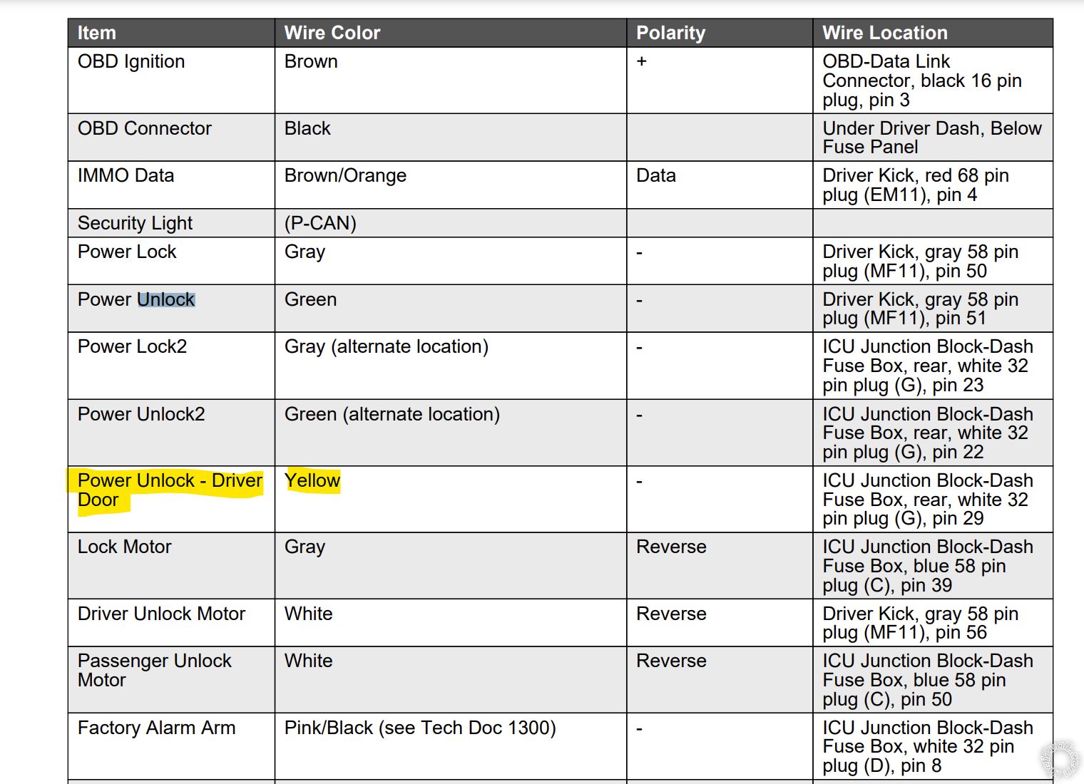
So Im looking over this newly received PDF for direct wire for this generation of vehicles and Im guessing that:
Power Unlock - Driver Door
Yellow - ICU Junction Block-Dash
Fuse Box, rear, white 32
pin plug (G), pin 29
may also work out of the box since its negative polarity, but havent tested.
Pulled the info from this PDF:
2021 KIA Soul DirectWire Vehicle Information (PDF)
-------------
2017 soul, 2021 soul