adding cockpit speakers to stereo
Printed From: the12volt.com
Forum Name: Marine Electronics
Forum Discription: Boat Stereos, Security, Navigation, Lights, Switches, Gauges, etc.
URL: https://www.the12volt.com/installbay/forum_posts.asp?tid=132514
Printed Date: March 28, 2026 at 2:36 PM
Topic: adding cockpit speakers to stereo
Posted By: peaboy
Subject: adding cockpit speakers to stereo
Date Posted: October 28, 2012 at 10:43 PM
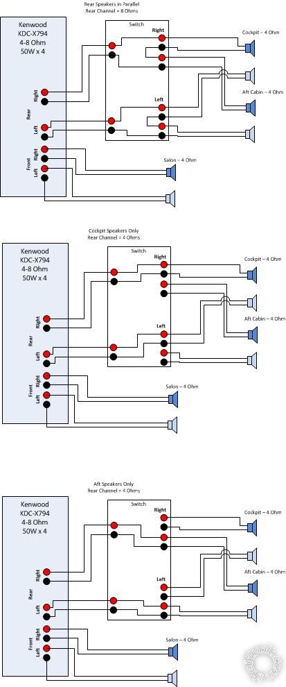
I have a Kenwood KDC-X794 which can handle 4-8 Ohm speakers and will deliver 50Wx4.
I currently have salon speakers (4 Ohm) on the front channel and aft cabin speakers on the rear channel (4 Ohm). I want to add a set of cookpit speakers to the rear channel (also 4 ohm). I know if I wire the new speakers in parallel with the aft cabin I will get 8 ohms and everything is fine. But the problem with that is I also want to be able to turn on\off the cookpit speakers or the aft cabin speakers so that I can have all four rear speakers or just one set of them on. Attached is a diagram which shows basically what each state should look like from a wiring perspective. I'm not sure the proper way top draw the switch schematically, but I think you get the idea. There don't seem to be any true 12V speaker selectors on the market. Anyone know of a switch which can handle this kind of configuration?
Thanks!
-patrick -------------
Replies:
Posted By: Ween
Date Posted: October 28, 2012 at 11:38 PM
hi,
use a SPDT 3 position center off switch, and 2 DPDT(or DPST) 12 volt relays, 5 amp contacts should be more than adequate. have the normally open contacts of each relay wire across each pair of speakers. wire the relay coils to the switch, each relay to one side of the switch.
the relays will shunt the pair of speakers they are connected to, giving you cookpit, both, and aft cabin settings.
mark
Posted By: peaboy
Date Posted: October 29, 2012 at 4:19 AM
Thanks a lot for the help. I modified my drawing to have two DPDT RElays and a SPDT switch and a 12VDC power surce. I've spent several hours trying to figure out how this shoudl be wired and I guess I'm not understanding it.
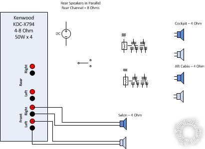
Can you walk me through how the output of the deck connects to the relays and then how the speakers connect to the relay. I think each relay will be controll Rear Left and Rear Right and if that's the case I could see how the relay could toggle between each pair of speakers by hooking one set to the NC and one to the NO on each relay, but I'm not seeing how I get Aft, cookpit, and Aft + cookpit.
I'm not that up on how relays work though.
Thanks,
Patrick -------------
Posted By: Ween
Date Posted: October 29, 2012 at 6:30 PM
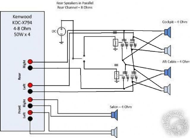
this should work
Posted By: peaboy
Date Posted: October 29, 2012 at 9:31 PM
I NEVER would have figured that out. I can't wait to get the pieces and give it shot. I'm on the boat in Mexico so getting things can take soem time, but I will definitely let you know how it goes.
Thanks a lot!
-patrick
Posted By: peaboy
Date Posted: November 23, 2012 at 1:51 PM
Finally got around to updating my drawing. TinyCad somuch better than Visio for this!
This week I'll be off to Steren and Autozone in Puerto Vallarta to try and find the parts. If not, then I'll have friends bring them in from the US. 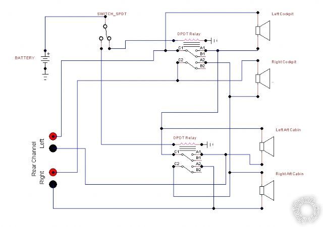
Posted By: peaboy
Date Posted: November 23, 2012 at 2:00 PM
I should mention one thing. I'm not 100% sure that SPDT id the right icon. It should be a SPDT ON-OFF-ON. I'm not sure if that is conveyed here or not.
Posted By: Ween
Date Posted: November 23, 2012 at 5:48 PM
put an extra circle between the lower two
Posted By: peaboy
Date Posted: December 27, 2012 at 5:26 PM
OK, finally got all the pieces and there was no surf so I got around to working on this.
Its all wired up, but its not working as planned. With it all wired up ALL the speakers are on regardless of the position of the switch. When I flip the switch though, I do see the green indicator relay and I do see the relay close. Very confusing...
The relays are IDEC RH2B-UL and the switch is an Amico 3 position on/off/on SPDT. I numbered the relay connections on the drawing to match the socket in the IDEC documentation.

You can see more pics in this Flickr Set for the Speaker Switch.
Any ideas?
Thanks a lot,
patrick
Posted By: Ween
Date Posted: December 27, 2012 at 9:29 PM
do the relays have sockets with screw terminals? manually add jumper wires to mimic the operation of the relay contacts to see if the speakers mute. or unplug relay and insert wires?
Posted By: peaboy
Date Posted: December 28, 2012 at 11:24 AM
Yes, if I jump the posts labeled 1 to 5 and 4 to 8 on a relay those speakers are disconnected.
Why is it with the switch in the circuit, I can see the relay close AND I see the indicator light come on but I don't achieve the same thing?
Thanks
-patrick
Posted By: peaboy
Date Posted: January 09, 2013 at 12:51 PM
Here is the final drawing of the working circuit.

Thanks a lot for all the help!
-patrick
Posted By: Ween
Date Posted: January 10, 2013 at 6:21 PM
you are welcome.
mark
Posted By: khill
Date Posted: September 04, 2013 at 9:29 AM
Here's the datasheet for IDEC RH2B-UL relays.
Posted By: khill
Date Posted: September 04, 2013 at 9:30 AM
|