528t pulse timer
Printed From: the12volt.com
Forum Name: Car Security and Convenience
Forum Discription: Car Alarms, Keyless Entries, Remote Starters, Immobilizer Bypasses, Sensors, Door Locks, Window Modules, Heated Mirrors, Heated Seats, etc.
URL: https://www.the12volt.com/installbay/forum_posts.asp?tid=100016
Printed Date: May 14, 2026 at 10:44 PM
Topic: 528t pulse timer
Posted By: c-west_civic
Subject: 528t pulse timer
Date Posted: December 14, 2007 at 4:07 PM
Im trying to install a light in my car ( 2 actually ) and I am using the 528T pulse timer, but am definetly not an electronic whiz. The lght Im trying to install goes on my steering column to iluminate my floor when the door opens. The other light is a key hole ring light. The harness that is used has 3 wires ( white, green, red ). Im pretty positive the white wire is ground, because it is split off into 2 wires that go to each light. Then the red and green wire go to one of the lights. See diagram below 
I need to install the timer so that when I open my door, the lights come on. When I shut my door, all interior lights go out, EXCEPT the column and key hole light. They are to stay light and then dim as to what ever I set the 528T at. Coming off the door switch, is 1 wire, which is green. Can anyone draw me up a diagram showing me how to install this so it works properly? I would be most appreciative.
Replies:
Posted By: c-west_civic
Date Posted: December 14, 2007 at 4:16 PM
Here is the 528T pulse timer wire codes. Sorry forgot to add them. 
Posted By: dualsport
Date Posted: December 16, 2007 at 7:55 AM
Do you still need the two lights to be independently controlled by whatever turns them on/off now? I assume since they have different color wires they aren't connected together.
If you want them to just turn on with the door opening and closing, it might be a bit easier; you could just use the door trigger for your timer module, setting up the module to trigger when it changes state from (-) to (+) (or however it changes when you shut the door).
Connect up common (term 30) going to the lights,
normally closed (87A) to the original wire that powers the lights,
and the normally open (87) to a 12V source.
This way the lights operate normally from whatever triggered them before, and when you open and close the door, the timer module gets triggered, and the relay kicks in for the delay time. The lights get powered directly from your 12V source, and turn off again when the timer module is done. If you want to keep the two lights separate you just have to use another relay, to keep them isolated.
Posted By: c-west_civic
Date Posted: December 16, 2007 at 8:55 AM
So I dont need to hook up the none of the 3 wires coming off the bottom of the diagram for the pulse tmer? Just connect yellow to both green and red coming off column light Connect orange to green wire that comes from dome light Brown into any 12 volt source that is constant Ground out the wite wires from the column light Thats it???
Posted By: dualsport
Date Posted: December 16, 2007 at 9:06 AM
You still have to connect up the power wires to the module, if that's what you mean.
And you have to connect up the trigger wire to your door switch connection, and check that your module is set up as needed to trigger when the door is closed. Depending on just how your door switch wire behaves, you may have to cut the blue loop wire to set it up.
If you can find out how it behaves when the door is opened or closed, it would determine how your module needs to be set up.
Posted By: c-west_civic
Date Posted: December 16, 2007 at 9:34 AM
Wow ok, Im lost again. So, red off timer to a constant power, black off timer to a ground. "you have to connect up the trigger wire to your door switch connection" i thought i did this when I connected the orange wire to the green dome light wire?
Posted By: dualsport
Date Posted: December 16, 2007 at 9:52 AM
I thought the lights you have now, for your column floor light and keyswitch light, were powered from some other kind of circuit separate from the door switch. If it's the same, then you would connect the same wire to two places on the module, also hooking your door switch wire to the trigger input to the module.
If you have a meter, you should measure the voltages of the wires you're planning to use to see if they work the way you expect.
The idea is that the module will provide the same connections as you have now, using the COM and normally closed terminals, and then when you trigger the module, it opens up the connection, and instead sends 12V from the normally open terminal to your light, connected to the COM.
It sounds complicated trying to describe it in words, but really the trickiest part is just making sure your module trigger is set up right, so that it only triggers when you close the door. Hotwaterwizard has a knack for drawing out things pictorially, maybe he can sketch it out to make it clearer.
Posted By: c-west_civic
Date Posted: December 16, 2007 at 9:52 AM
Posted By: c-west_civic
Date Posted: December 16, 2007 at 9:54 AM
Oh no the column light and key hole light wasnt an added feature on the car, so Im adding to it.
Posted By: dualsport
Date Posted: December 16, 2007 at 10:03 AM
If you confirm that the green (+ lead coming from dome light) wire is 12V when the door is open, and ground when the door is closed, then it should work, assuming you don't have some other convenience delays in the car that affect the light.
The green and red (+ leads coming from lights) should be the wires going to your lights, with +12 turning them on.
That should work, and you shouldn't need to cut the blue wire loop, so that it triggers when it goes low (when you shut the door and the light goes out)
Posted By: c-west_civic
Date Posted: December 16, 2007 at 10:17 AM
So then the diagram I drew up last, should work providing the confirmation of power when door open?
Posted By: c-west_civic
Date Posted: December 16, 2007 at 12:04 PM
Ok, found out ( and excuse my ignorance if I use wrong terms ) that when the door plunger is pushed in, it breaks the circuit, an when the door plunger comes out, it completes the circuit causing the light to come on. Also, if i hook it up the way drawn up, if its wrong, will I blow the pulse timer?
Posted By: c-west_civic
Date Posted: December 16, 2007 at 12:58 PM
Ok, wait, I just got some new info. The coumn light comes on when the doors open and shus off when door closes ( this I can wire up no problem )The key hole light is what will stay on for 10 seconds. SO, would I wire it like so: Door switch wire into yellow 30 common. red + from keyhole light to brown 87 normally open. black from timer ground and red from timer to constant power?
Posted By: dualsport
Date Posted: December 16, 2007 at 1:22 PM
So the only one you want to have timed is the keyhole light?
The diagram you drew ealier should still be okay, just remove wire to the column light if you don't want that on the timer. The common 30 should go to your keyhole light, not the door switch wire- reverse it from what you just described.
Posted By: c-west_civic
Date Posted: December 16, 2007 at 2:01 PM
Yes just the keyhole light needs the timing feature. Door switch to 87 brown normally open. Red + from keyhole light to 30 yellow common. Black from timer to a ground. Red from timer to a constant power. All other wires, orange 87a not used, black with stripe not used and leave the bue looped wire uncut.
Posted By: dualsport
Date Posted: December 16, 2007 at 4:00 PM
87a to Door Switch wire (this has to be 12V with door open, gnd when closed)
87 to constant power
black with stripe to the Door switch wire (this is the trigger)
Posted By: c-west_civic
Date Posted: December 16, 2007 at 8:33 PM
Ok, so lets see if got this straight this time ( sorry ) Black w/ stripe and 87a both to the door trigger wire 87 and red wire of timer to a constant ground 30 common goes to red + of keyhole light black goes to a ground If that looks right, Ill run the test tommorrow. Thanks for your patience
Posted By: dualsport
Date Posted: December 17, 2007 at 7:37 AM
Almost there-
87 and red wire of timer to constant 12V, not constant ground..
Posted By: c-west_civic
Date Posted: December 17, 2007 at 8:23 AM
Opps my bad, I meant to type power. :)
Posted By: c-west_civic
Date Posted: December 18, 2007 at 9:01 AM
dualsport, wired up like we talked about, but somthings not rght. First off, when I wire in the column light, its very dim, and also dims the dome light light. Second, when I have it all installed, the column light dont come on. Third, the keyhole light does do the timer delay, but not every time the door opens. Like I open the door and the light comes on, stays on for the duration set, then clicks off. If I open the door right after goin out, the light doesnt come back on. Its like the relay has to reset or something??? Im gonna go back out today and mess around with it, to see if I can cancel out any problems, but if you can think of something ( or anybody for that matter ) please post up. Thanks.
Posted By: dualsport
Date Posted: December 18, 2007 at 9:11 AM
Did you use a meter to check the voltage of your dome light switch wire to make sure it goes to 12V when the door is open, and ground when it's closed? If it's reversed it won't work properly, so you have to make sure before hooking it up.
Posted By: c-west_civic
Date Posted: December 18, 2007 at 10:33 AM
Yup. I even have an old door trigger that I opened up to see whats going on. When the trigger is in ( door closed ) the ground gets disonnected. When the trigger is out ( door open ) the ground is touching causng the circuit to complete. Am I wrong in my thinking?
Posted By: c-west_civic
Date Posted: December 18, 2007 at 10:42 AM
Ok, I also just did this Took it all apart, and ran just the column light postive to the door trigger positive and grounded out the column negative. Both the dome lght and column light came on but at half power. Soon as I let go of the column light positive, the dome light resumed its full brightness.
Posted By: c-west_civic
Date Posted: December 18, 2007 at 11:29 AM
Maybe this will help. So far I tried to hook the column light all by it self to the green on the driver door switch just before the integrated control unit and also the light green w/ red stripe on the passenger door switch. Both times, both lights dim. 
Posted By: c-west_civic
Date Posted: December 18, 2007 at 11:53 AM
Oh yea, trying to give you all the info, so without a factory radio installed in the car, the keyless entry doesnt work ( only by alarm, not yet istalled ) so in order for me to get the dome lights to work, I had to jump the light green wire with red strip coming from the keyless box to the light green wire with black strip coming from the keyless box ( just connecting the cicuit ). When I ran the multimeter on that connection, power outage only read about 3 volts. Yet power to the dome reads 12
Posted By: c-west_civic
Date Posted: December 18, 2007 at 2:33 PM
Ok, took my car further apart. 2 wires running from dome. White w/ red stripe ( wire 1 ) =12 volts constant. Light green w/ red strip ( wire 2 above diagram comin from dme light ) = 3 volts Ive tapped into so many wires coming from that diagram and stil cant find a solid light output. Only oneis the white w/ red strip, but by doing so, its just a constant on.
Posted By: c-west_civic
Date Posted: December 18, 2007 at 6:35 PM
Ok, Im super close but, something is wired wrong still. Everything is working properly except the keyhole light. And by this I mean, when the door opens, the light comes on, if door remains open, the timer will shut the light off. If I close my door before the timer duration is up the light will go off. Im thiking it has to do with the black strip maybe???
Posted By: c-west_civic
Date Posted: December 18, 2007 at 8:22 PM
Ok it wasnt. Here is what I got so far to make it 95% work 
Posted By: dualsport
Date Posted: December 18, 2007 at 8:43 PM
Your door switch is grounded when the door is open, and goes high when the door is closed; that's how most cars are, but it's reversed from what you described. I'll see if I can take your picture and make updates to it so you can try it out- stay tuned..
Posted By: dualsport
Date Posted: December 18, 2007 at 9:03 PM
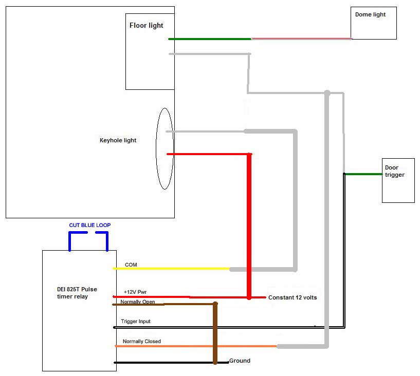
Try this:
Posted By: c-west_civic
Date Posted: December 18, 2007 at 9:17 PM
Am I still suppose to take the white ( grey in pic ) wire that comes from the floor light and go to the door trigger and the orange ( normally closed) wire or did you mean to erase it?
Posted By: c-west_civic
Date Posted: December 18, 2007 at 9:36 PM
Ok did it just like you showed in the photo. It works almost and if thats best I can get thats ok. Whats happening is. Door is shut, all lights off. Open door, dome and floor light come on only. When you shut the door, then the keyhole light comes on. I think its supose to be all 3 lights come on when door opens, and when door closes, the keyhole stays on by itself for specified time. Is that possible?
Posted By: dualsport
Date Posted: December 18, 2007 at 11:19 PM
Do you hear a click from the timer when you open the door, or only when you shut the door? I would expect it should only click when you close the door and the trigger line goes high.
Unless the wire colors are not as stated on the diagram you showed for the timer, the keyhole light should be on whenever the door is open, because it should ground the yellow COM wire going to the keyhole white wire. It wouldn't even make a difference if the timer triggered or not, since it would just be switching between two grounds
Make sure your Constant 12 volts wire is really constant and not connected to some switched source.
Posted By: c-west_civic
Date Posted: December 18, 2007 at 11:21 PM
Ok, if you give me second, Ill get all that info for you.
Posted By: c-west_civic
Date Posted: December 18, 2007 at 11:32 PM
Constant is a constant Click happens when I open the door, then after set time, it clicks again. That diagram I pulled from this site and its a match for the copy DEI sent me. I also just noticed that this set up works with my dome light swith in the off position ( guessing thats my fault for the choice of power wire )
Posted By: dualsport
Date Posted: December 18, 2007 at 11:46 PM
Did you cut the blue wire loop on the timer? According to the diagram it says it should trigger when the negative goes away, which I take to mean when the ground is removed (or when the door closes)
If you did that already, maybe you can try reconnecting the blue wire loop to see if the description is backwards.
Posted By: c-west_civic
Date Posted: December 18, 2007 at 11:48 PM
Yup I cut the blue, lll go try and connect and see what happens
Posted By: c-west_civic
Date Posted: December 18, 2007 at 11:51 PM
No change in reconnecting the blue loop.
Posted By: c-west_civic
Date Posted: December 19, 2007 at 12:04 AM
Also what is happening, when the keyhole is triggered, if I dont shut my door, the keyhole will still turn off. It should have power till I shut the door and then turn off by whatever is set by the timer.
Posted By: dualsport
Date Posted: December 19, 2007 at 12:05 AM
Suppose you test the module by disconnecting the BLACK/ white striped trigger wire from the door trigger wire, and just touch that trigger wire to ground. It should click on when you remove it from the ground, staying on until the timeout period. It shouldn't click when you first touch it to ground (though that could depend on whether they designed it with debouncing circuitry).
See how it reacts when you do this; maybe the timer module isn't detecting the change.
With the wire reconnected, take your meter and measure the voltage on the wire with the door closed, and open. It could be the door switch isn't grounding it enough for it to consider it to be a low (think you mentioned 3V earlier, with the door open). Are you measuring it from one of the passenger door switches, and testing it by opening the driver side door? There's a diode on the driver side door switch, so it won't provide as good a ground as the passenger doors.
Also try testing it by opening and closing a passenger side door instead of the driver side, if that's what you've been doing- that might be another clue.
Posted By: c-west_civic
Date Posted: December 19, 2007 at 12:09 AM
Ok, ill go do it now. Did you notice my last post?
Posted By: dualsport
Date Posted: December 19, 2007 at 12:13 AM
c-west_civic wrote:
Also what is happening, when the keyhole is triggered, if I dont shut my door, the keyhole will still turn off. It should have power till I shut the door and then turn off by whatever is set by the timer.
Are all three wires of the timer relay connected to ground? If the Normally Closed wire is not connected right, then when the timer times out, the relay opens up the connection to the yellow Common wire, and the keyhole will turn off. If it's connected to the door switch line, then it should be on as long as your door is open.
If everything looks connected properly, you can test if the timer relay contact for the Normally Closed is not working by just temporarily connecting the Normally Closed and the Common wires of the relay together, with the door open. If the keyhole then turns on as long as the door is open, then there's a problem with the timer relay.
Posted By: c-west_civic
Date Posted: December 19, 2007 at 12:30 AM
Passenger door doesnt effect any of the lights, except the dome. Disconnected black w/ strip it triggers the timer and keyhole light comes on. No clicking touching it to earth ground When touching the black w/ strp by it self to door trigger ground, it goes on with door opening. With everything wired back up like the diagram you drew, 12 volts door open and 12 volts when door closed.
Posted By: dualsport
Date Posted: December 19, 2007 at 12:42 AM
If it's 12 volts open whether the door is open or closed, then that trigger line isn't the right one. It has to be a line that goes to ground when the door is open, and goes back up to 12 when it's closed.
In that wiring diagram you have in an earlier post, it should be the LT GRN/RED wire. If you connected it to the WHT/RED, it won't switch.
Posted By: c-west_civic
Date Posted: December 19, 2007 at 12:45 AM
dualsport wrote:
Are all three wires of the timer relay connected to ground? If the Normally Closed wire is not connected right, then when the timer times out, the relay opens up the connection to the yellow Common wire, and the keyhole will turn off. If it's connected to the door switch line, then it should be on as long as your door is open.
If everything looks connected properly, you can test if the timer relay contact for the Normally Closed is not working by just temporarily connecting the Normally Closed and the Common wires of the relay together, with the door open. If the keyhole then turns on as long as the door is open, then there's a problem with the timer relay.
I have normally open and black going to earth ground and normally closed going to door trigger ground With everything hooked up as normal, I took the normally closed and touched the common and no light. Also as it sits right now, the lights are functioning the same with the normally closed not touching anything
Posted By: c-west_civic
Date Posted: December 19, 2007 at 12:48 AM
dualsport wrote:
If it's 12 volts open whether the door is open or closed, then that trigger line isn't the right one. It has to be a line that goes to ground when the door is open, and goes back up to 12 when it's closed.
In that wiring diagram you have in an earlier post, it should be the LT GRN/RED wire. If you connected it to the WHT/RED, it won't switch.
I tried that wire in several spots along that wire. Everytime I connected to it, the lights would just barely glow, as if it wast getting enough voltage. Thats when I was getting the 3 volts reading
Posted By: c-west_civic
Date Posted: December 19, 2007 at 3:49 PM
Hey guess what? Its good to go. Told you I was an idiot when it came to this stuff. I was out there today messing with it and I was reading one of the wires wrong. I still had the white ground of the keyhole to a ground instead the common, which had me not having the red to a constant. I also figured out which set of wires I need to plug into to make sure its off in the off position. Huge thanks man, if I could shake your hand I would. Also thanks for your patience thru this.
Posted By: dualsport
Date Posted: December 19, 2007 at 4:29 PM
Glad it finally worked out! 
|
