1999 dodge ram door locks
Printed From: the12volt.com
Forum Name: Car Security and Convenience
Forum Discription: Car Alarms, Keyless Entries, Remote Starters, Immobilizer Bypasses, Sensors, Door Locks, Window Modules, Heated Mirrors, Heated Seats, etc.
URL: https://www.the12volt.com/installbay/forum_posts.asp?tid=100158
Printed Date: May 14, 2026 at 8:15 PM
Topic: 1999 dodge ram door locks
Posted By: fingerbang
Subject: 1999 dodge ram door locks
Date Posted: December 18, 2007 at 2:12 AM
Good day everyone, as you can see first post, but i have looked for weeks not to find correct information and just want to verify something.
I have a 1999 Dodge ram 1500 5.2L.
I installed a remote/alarm and i am having troubles with my door locks, from what ive been reading alot of people do. And it seems, there is alot of false information out there.
Anyways, i have gone through 2 different wiring diagrams, both with 2 relays and i blew the fuse for my door locks many times.
Can someone post the CORRECT wiring diagram for me to follow?
I did search and THINK i now have the right one, but i really want to be sure that the next time i wire this up i don't blow any more fuses and hopefully i can put my truck back together.
ps. i think that the correct one is the DODGE RAM FULL SIZE 3/5 WIRE DOOR LOCK SYSTEM.
am i correct?
thanks alot for the assistance.
Replies:
Posted By: Twelvoltz
Date Posted: December 18, 2007 at 6:39 AM
If the 99 Ram came with keyless from the factory it would have a positive pulse for lock and a 5-wire for unlock. If it did not come with factory keyless it is 5-wire for both.
Here is a diagram for the positive pulse door locks: link
Here is a diagram for the 5-wire door locks: link
If you are blowing a fuse I would have to think you have it wired incorrectly. ------------- Installer, IT support, and FFL. I need less hobbies.
Posted By: fingerbang
Date Posted: December 18, 2007 at 1:27 PM
i keep forgetting to mention that it does not have factory keyless, just power door lock/unlock.
That is odd, i followed that diagram to a T and it blew fuses, i will get new relays and retry.
Posted By: thepencil
Date Posted: December 18, 2007 at 2:13 PM
Use the 5-wire door locks diagram without factory keyless. ------------- Be careful whose advice you buy, but be patient with those who supply it. 
Posted By: fingerbang
Date Posted: December 18, 2007 at 2:27 PM
now heres a question,
Doing the proper 5 wire diagram, if i did NOT have the +12V connected, would this cause an issue?
Posted By: JWorm
Date Posted: December 18, 2007 at 5:47 PM
fingerbang wrote:
now heres a question,
Doing the proper 5 wire diagram, if i did NOT have the +12V connected, would this cause an issue?
Yes, the issue would be the locks would not operate from the remote.
The likely problem you are having is that you reversed 87a and 30. How are you determining "motor" vs. "switch" side?
Posted By: fingerbang
Date Posted: December 18, 2007 at 6:00 PM
JWorm] wrote:
fingerbang wrote:
now heres a question,
Doing the proper 5 wire diagram, if i did NOT have the +12V connected, would this cause an issue?
Yes, the issue would be the locks would not operate from the remote.
The likely problem you are having is that you reversed 87a and 30. How are you determining "motor" vs. "switch" side?
with the 2 wires (lock/unlock) cut, i ground 1 end of my meter and the other goes to 1 wire of the 2 pairs, if there is +12v then that is the switch side, and the other is motor, i then repeat for the other set of wires.
Posted By: fingerbang
Date Posted: December 19, 2007 at 4:24 PM
fingerbang wrote:
with the 2 wires (lock/unlock) cut, i ground 1 end of my meter and the other goes to 1 wire of the 2 pairs, if there is +12v then that is the switch side, and the other is motor, i then repeat for the other set of wires.
correct?
Posted By: auex
Date Posted: December 19, 2007 at 4:31 PM
Are you the original owner of the vehicle? Are you certain that it didn't have the keyless entry option from the factory? At any rate to make sure, reconnect one of the motor wires and see if the locks work, try both lock and unlock. If it does either with only 1 wire disconnected then isn't 5 wire reverse polarity.
-------------
Certified Security Specialist
Always check info with a digital multimeter.
I promise to be good.
Tell Darwin I sent you.
I've been sick lately, sorry I won't be on much.
Posted By: fingerbang
Date Posted: December 19, 2007 at 11:16 PM
auex] wrote:
Are you the original owner of the vehicle? Are you certain that it didn't have the keyless entry option from the factory? At any rate to make sure, reconnect one of the motor wires and see if the locks work, try both lock and unlock. If it does either with only 1 wire disconnected then isn't 5 wire reverse polarity.
i am the second owner, i did get my build sheet and it did not show factory keyless on it, but i will try what you say.
So, if i get this straight.
leave 1 set of wires connected, and one set split.
if EITHER lock or unlock WORK then i HAVE factory keyless?
am i reading this correct?
Posted By: JWorm
Date Posted: December 20, 2007 at 4:48 PM
You should be testing for "switch" side when only 1 wire (the wire you are testing) is cut. Cutting both wires and then testing for "switch side" may give you misleading results.
Posted By: ralphtonka
Date Posted: December 20, 2007 at 10:21 PM
If factory keyless there will be brown box above gas pedal doorlocks are +, must pull dr door lock sw and install 3A diode on pink purple wire
Posted By: fingerbang
Date Posted: January 05, 2008 at 1:54 PM
ok now i really need help.
i have followed 3 similar diagrams and they all do pretty much nothing except blow my fuses.
heres what i do:
ORANGE / violet connected
pink/violet cut.
with my tester i connect black to ground and check the pink and violet wires for 12 volts when i hit the UNLOCK SWITCH, 1 of the wires will give me 12 volts on UNLOCK and the other will give me 12volts when i put the switch to LOCK. It will do this for both sets of wires.
IS THIS NORMAL???
I am soo bloody confused. I have verified my wires soo many times and they are correct.
am i using the wrong fuses? they are standard heavy duty 30amp auto relays
Posted By: JWorm
Date Posted: January 05, 2008 at 3:35 PM
fingerbang wrote:
ok now i really need help.
i have followed 3 similar diagrams and they all do pretty much nothing except blow my fuses.
heres what i do:
ORANGE / violet connected
pink/violet cut.
with my tester i connect black to ground and check the pink and violet wires for 12 volts when i hit the UNLOCK SWITCH, 1 of the wires will give me 12 volts on UNLOCK and the other will give me 12volts when i put the switch to LOCK. It will do this for both sets of wires.
IS THIS NORMAL???
am i using the wrong fuses? they are standard heavy duty 30amp auto relays
Yes, that is normal
Leave the ORANGE / purple connected. Cut the pink/violet. Connect the meter as you have been doing. Hit UNLOCK on the door. If it shows +12v, you have the switch side of the UNLOCK wire. Connect it to 87a of the relay. If it does not show 12v, you have the motor side of the UNLOCK wire. Connect it to 30. You are testing the UNLOCK wire. Pay no attention to what happens when you hit LOCK on the door.
After the pink/violet has been reconnected (or connected to the relay you are installing then you can cut the ORANGE / purple LOCK wire. Test as before, but only hit the LOCK button on the door. The side that shows 12v gets connected to 87a. The other side goes to 30.
I would use a smaller fuse. Either a 15 or 20 amp fuse. Two doorlock motors should never pull more current than that.
Posted By: moonliter
Date Posted: January 05, 2008 at 3:49 PM
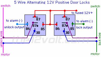
Here is how I would do to find out the switch side and the motor side of the lock & unlock wires. ORANGE / violet (lock wire), pink/violet (unlock wire) , cut both wires at the driver kick panel, according to my chart, the driver side is the master so you test with the master switch. put the red lead of your dmm on the ORANGE / violet (lock), the black lead on the pink/violet (unlock) on the same side of the cut wires. Test the side that when you press the lock button, your dmm shows +12v , read -12v when you press the unlock . When proven then this will be your switch side of the lock/unlock wires. Connect the switch side of ORANGE / violet to 87a of lock relay. the motor side to 30 of the lock relay. 86 & 87 to +12v, 85 to the lock output (-) from rs Connect the switch side of pink/violet to 87a of the unlock relay. the motor side to 30 of the unlock relay. 86 & 87 to +12v, 85 to the unlock output (-) from rs
Posted By: fingerbang
Date Posted: January 05, 2008 at 4:23 PM
Posted By: fingerbang
Date Posted: January 05, 2008 at 4:32 PM
ahhh i cant edit....
unlock side is pink/violet
lock side is ORANGE / violet
with pink/violet cut, and i hit the unlock i can get the 12V+ on one of the 2 wires that is the switch side (87a) of unlock and therefore the other goes to 30 (motor)
with ORANGE / violet cut, and i hit the lock i can get the 12V+ on one of the 2 wires that is the switch side (87a) of lock and therefore the other goes to 30 (motor).
i have wired 100% exactly as above and when i do that, it blows the 12V+ fuse right away, without pressing anything.
but reverse the 87a and 30 on each relay and the fuse does not blow, but lock wont work.
Posted By: fingerbang
Date Posted: January 05, 2008 at 4:36 PM
fingerbang wrote:
ahhh i cant edit....
unlock side is pink/violet
lock side is ORANGE / violet
with pink/violet cut, and i hit the unlock i can get the 12V+ on one of the 2 wires that is the switch side (87a) of unlock and therefore the other goes to 30 (motor)
with ORANGE / violet cut, and i hit the lock i can get the 12V+ on one of the 2 wires that is the switch side (87a) of lock and therefore the other goes to 30 (motor).
i have wired 100% exactly as above and when i do that, it blows the 12V+ fuse right away, without pressing anything.
but reverse the 87a and 30 on each relay and the fuse does not blow, but lock/unlock wont work.
but reverse the 87a and 30 on each relay and the fuse does not blow, but lock/unlock wont work.
Posted By: moonliter
Date Posted: January 06, 2008 at 10:55 PM
fingerbang wrote:
i have wired 100% exactly as above and when i do that, it blows the 12V+ fuse right away, without pressing anything.
i hope you didn't connect the 12v+ to pin 30's instead of pin 87 of the relays. that would be a disaster, it will blow the fuse right away. 12v+ must connect to pin 87 of the relay only. Check your connections of the lock/unlock wires again.... switch side of the lock wire must go to pin 87a, motor side goes to pin 30 of the lock relay. switch side of the unlock wire must go to pin 87a, motor side goes to pin 30 of the unlock relay.
Posted By: fingerbang
Date Posted: January 07, 2008 at 1:04 AM
ive wired the relays EXACTLY as above's picture. with 12V+ going to the 4 pins.
Posted By: moonliter
Date Posted: January 07, 2008 at 1:20 AM
If you disconnect the wires at pin 30 & pin 87a on each relay, will the fuse still blow ?
Posted By: fingerbang
Date Posted: January 07, 2008 at 2:38 AM
i will try that, havent tried that yet.
|