rfid central locking.
Printed From: the12volt.com
Forum Name: Car Security and Convenience
Forum Discription: Car Alarms, Keyless Entries, Remote Starters, Immobilizer Bypasses, Sensors, Door Locks, Window Modules, Heated Mirrors, Heated Seats, etc.
URL: https://www.the12volt.com/installbay/forum_posts.asp?tid=106024
Printed Date: May 12, 2026 at 6:19 PM
Topic: rfid central locking.
Posted By: katq22
Subject: rfid central locking.
Date Posted: July 09, 2008 at 7:31 PM
I have purchased a cheap RFID kit off eBay that connects a relay (Basically outputs a small 12V current) when the token is put near the receiver, and disconnects after a time once the token is taken away.
How would I be able to set this up so that
1. When the relay is active a pulse is sent on the unlock signal
2. When removed a pulse is sent on the lock signal.
Thanks
Ben
Replies:
Posted By: i am an idiot
Date Posted: July 09, 2008 at 7:46 PM
That is going to be a piece of cake. I will post you a picture in a couple hours. Unless somebody beats me to it. It is going to take 3 relays, 2 capacitors 2 diodes and 2 resistors. Hint Hint
Posted By: katq22
Date Posted: July 09, 2008 at 8:44 PM
I am guessing it will use two of this setup linked together somehow. As it will be in a car it will need to be zero draw when in the locked state so as not to flatten the battery.
What program do you used for drawing diagrams? Are there any programs that you can make virtual circuits to test by turning the switch on and off?
Posted By: i am an idiot
Date Posted: July 09, 2008 at 8:46 PM
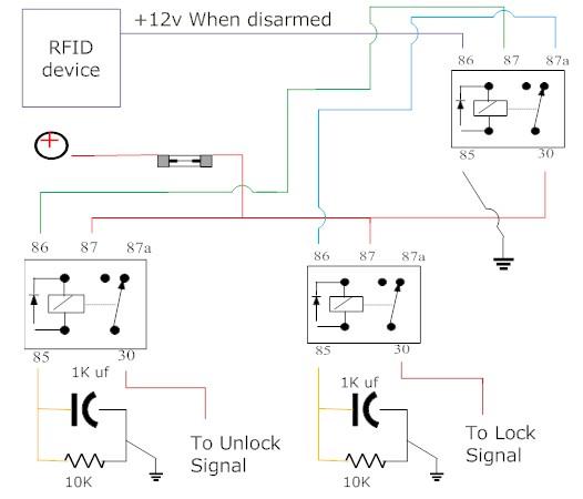
You will have to build 2 of the above. 1 will be for lock and the other for unlock. There needs to be a third relay wired as follows. If your rfid device outputs a positive voltage, that output wire to terminal 86 of the relay. Ground terminal 85. A Fused 12 volt constant source to terminal 30. 87A goes to the lock momentary relay pictured above. It connects to the wire labeled Switched 12v (+) 87 goes to that same wire on the momentary unlock relay pictured above. If your device provides you a ground output or if you have any other questions, let me know.
Posted By: i am an idiot
Date Posted: July 09, 2008 at 8:53 PM
There will be minimal current draw when in the locked position. It will be fractions of what an energized relay draws.
Posted By: katq22
Date Posted: July 10, 2008 at 1:13 AM
thanks for your rapid replys. Will this drain the battery if left for say a week or 2???
Posted By: i am an idiot
Date Posted: July 10, 2008 at 5:02 AM
The RFID device will pull way more current than the relay setup pulls. On paper the relays will draw 1.2 Milliamps of current. I will try to remember to build one today and give you an exact number. The 1000 mic cap may change the number a bit, but I do not think so. An energized relay draws 160 milliamps.
Posted By: howie ll
Date Posted: July 10, 2008 at 5:34 PM
Craig what am I not seeing here? Does the RFID unit supply the line to 85?
Posted By: i am an idiot
Date Posted: July 10, 2008 at 5:42 PM
He said it puts out a small 12 volt when the transmitter is in range. Yes I am assuming that it puts out a positive voltage. In my long post above, there is a third relay. I have the RFID output wire going to 86 and ground to 85. That relay depending on it's state will supply 12 volts to either one of the constant to momentary relays.
Posted By: katq22
Date Posted: July 10, 2008 at 9:19 PM
So is this basically how it would work? and what sort of a pulse would that deliver? How long? long enough to drive door locks? Can the cap or resistor be changed to change the pulse length, and what Wattage should the resistor be?
Thanks so much for your help.
Ben
P.S. I found a Demo of Smart Draw to make this drawing. Man that program is expensive.
Posted By: i am an idiot
Date Posted: July 10, 2008 at 9:28 PM
That looks like it.
Posted By: katq22
Date Posted: July 11, 2008 at 12:19 AM
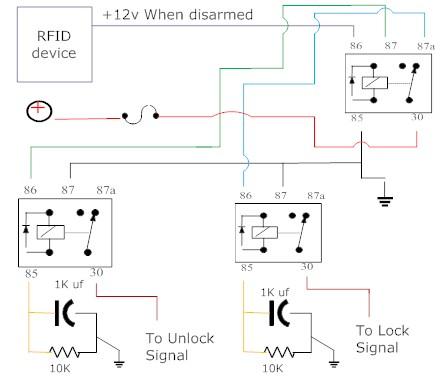
And this version would work with a Negative Pulse just like a standard car alarm yes?
Also you never responded about durations of the pulse. Is it possible to alter it by changing the Capacitor or Resistor?
Thanks
Ben
Posted By: i am an idiot
Date Posted: July 11, 2008 at 4:05 AM
Sorry I didn't see the question about the pulse length. Yes changing the capacitor will shorten or lengthen the pulse. 1000 mic around 1/2 second. 470 mic should be 1/4 second. 2200 mic 2 seconds. That is all theory, you may have to experiment. The only purpose of the resistor is to drain the cap and get it ready for the next cycle, changing the resistor will do nothing for the pulse length.
Your latest diagram, as is the first one is exactly what you need for the situation you described.
|