understandin this alarm diagram
Printed From: the12volt.com
Forum Name: Car Security and Convenience
Forum Discription: Car Alarms, Keyless Entries, Remote Starters, Immobilizer Bypasses, Sensors, Door Locks, Window Modules, Heated Mirrors, Heated Seats, etc.
URL: https://www.the12volt.com/installbay/forum_posts.asp?tid=106324
Printed Date: March 31, 2026 at 12:39 AM
Topic: understandin this alarm diagram
Posted By: h04n9
Subject: understandin this alarm diagram
Date Posted: July 23, 2008 at 4:35 PM
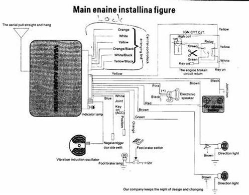
Hi everyone, i'm a 1yr auto apprentice mechanic and this is my first time to attempt installing an alarm. The alarm I have is a LJ-8(no name I guess) alarm system that I receive from a friend, he purchase it a year ago online somewhere. I'm trying to install this onto a 2003 Eclipse RS. I just needed something, a simple alarm system(keyless entry...) I'm having trouble with understanding the instruction of this diagram, sorry i'm very newbie!!:) I've included the diagram(below) for this alarm. But i'm not sure how/where to, the Relay get hook up to...also in the 2nd image link, I dont understand how to power lock goes. Could someone please show me where to hook the relay and the power lock for this system onto 03Eclipse. As I have alldata and Mitchell on demand so i can look up for thing if needs too. thanks in advance
Replies:
Posted By: h04n9
Date Posted: July 23, 2008 at 4:40 PM
sorrie, the link works but I didn't know how to add it properly have to copy and paste into address bar for it to work. thanks
Posted By: the12volt
Date Posted: July 23, 2008 at 5:20 PM
Use this button to add images to your post:  -------------  the12volt Support the12volt.com the12volt Support the12volt.com
Posted By: h04n9
Date Posted: July 24, 2008 at 2:50 AM
Posted By: KarTuneMan
Date Posted: July 24, 2008 at 11:46 AM
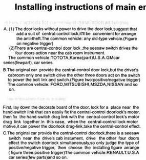
You unit has built in lock/unlock relays. This is why there are 6 wires. The six wires represent pins on a standard relay. 87, 87a, and 30. Normally open, normally closed, and common. You locks are negative pulse. Take the 2 wires labeled N.O. and ground them. One of the 2 is for lock, the other for unlock. You will NOT USE the N.C. This leaves the common.... on is your lock trigger, the other is unlock. There is a black plug in the drivers kick. Lock is purple, unlock is GREEN/ red. -------------
Posted By: h04n9
Date Posted: July 26, 2008 at 12:14 AM
This is the other diagram that i couldn't upload, I resize them differently, hopefully it will work this time. 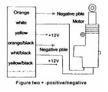
Posted By: h04n9
Date Posted: July 26, 2008 at 12:35 AM
Hi Kartune, THANKS for the reply. I took a look at the black plug and have locate the Lock/Unlock wires. I won't work on this until I know where to connect all the wires. From the diagram, N.O which is the Orange+ORANGE / blck to ground. Which one should i leave out? Also the diagram in the third post, there's a relay in the top-right corner. I dont understand how to connect them. I dont know if this is right, so Yellow from alarm to Yellow of Relay, White of alarm to White of relay, Green of Relay to Green(+) of Ignition switch Harness??? Then there is another Green of Relay and Green from alarm that doesn't show going anywhere. What is this relay for, starter kill? thanks
Posted By: KarTuneMan
Date Posted: July 26, 2008 at 12:40 AM
Leave out BOTH normally closed. (87a)
-------------
Posted By: h04n9
Date Posted: July 26, 2008 at 12:57 AM
KarTune, I don't know much about electrical yet. Can you be abit patient with me... How do i know out of the six wires which one is 87a NClosed? I have posted a new diagram 2 post up, please take a look? Could you also explain to me for the relay in the first diagram please?
Posted By: h04n9
Date Posted: July 27, 2008 at 2:42 PM
How/where do i connect the relay, for the first diagram in the 4th post (right top corner), please someone help? thnaks
|