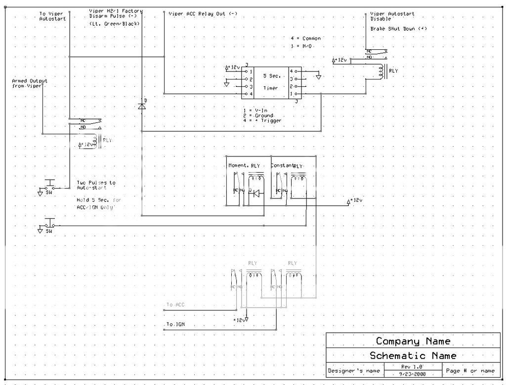
I redid my design using a pair of SPDT relays for momentary/constant output instead of that industrial AB latch relay in my previous schematic....
This one should be much easier to build. Have a look, let me know if you see any problems....thanks
https://i102.photobucket.com/albums/m91/WuNgUn/Misc/Autostart.jpg
The relay on the left hand side appears to be energized whenever the alarm is armed - if using a standard bosch relay that will kill the battery in a matter of days.
I'm guessing that this allows you to drive the car without any key at all? What did you do about the mechanical steering wheel lock? What kind of car did you install this in?
-------------
Kevin Pierson
KPierson wrote:
The relay on the left hand side appears to be energized whenever the alarm is armed - if using a standard bosch relay that will kill the battery in a matter of days.
I'm guessing that this allows you to drive the car without any key at all? What did you do about the mechanical steering wheel lock? What kind of car did you install this in?
The relay on the left is only to disable the start button when the alarm is armed...when it's disarmed, the start button functions normally...maybe I should use a micro power relay?
Yes, no key...removing the key barrel/mechanical wheel lock from the car completely.
This is going into an SVT Focus...it had PATS, so I need to wire in the DEI bypass into the system as well. I wish I could retain the PATS but be able to have it pick up the key in my pocket!! The field energizer isn't that strong however...
You will need a relay that draws the absolute least amount of current that you can find.
Most cars, from the factory, draw around 35mA at rest. The general rule of thumb is to keep all current draw under 50mA at rest, so you only have 15mA to work with, and you know the alarm system itself will pull some power when the car isn't on.
I think I would go as far to drop the relay all together and replace it with an NPN transistor. You can wire the emitter to ground through the swithch, wire the base to the ground when armed output with a 10K pull up resistor to constant 12vdc, and the the collector would be your (-) output. If you find a quality transistor with a beta close to 100 you'll have about 120mA of current on the output, and it will only pull 1.2mA when the alarm is armed.
Basically, the 10K resistor will turn the transistor on and allow the ground to pass through it. However, when the ground when armed output turns on the 10K resistor will turn from a pull up resistor to a load resistor and the transistor will shut off, as no current will flow to it.
That might be worth looking in to, if you can get away with only 120mA of (-) output.
-------------
Kevin Pierson
Wow...I like the idea of that!
Could you show me a schematic?
I'm also integrating a 5W solar panel in the sunroof visor to help with the 'sleep mode' draw on my carputer...it'll BARELY cover that draw, but for extended
periods with the car at rest, I'll put it into normal shutdown...
#erh, there's no sleep draw on the cars computor, after 2001 over here they all had sleep modes.
I'm guessing he is installing a carPC and it in standby mode will still require some power!
-------------
Kevin Pierson