diode to door trigger
Printed From: the12volt.com
Forum Name: Car Security and Convenience
Forum Discription: Car Alarms, Keyless Entries, Remote Starters, Immobilizer Bypasses, Sensors, Door Locks, Window Modules, Heated Mirrors, Heated Seats, etc.
URL: https://www.the12volt.com/installbay/forum_posts.asp?tid=108598
Printed Date: May 10, 2026 at 11:11 PM
Topic: diode to door trigger
Posted By: chadstrawn
Subject: diode to door trigger
Date Posted: November 01, 2008 at 5:00 PM
ok, so i work on police cars installing things for a to z. recently doing an alarm i did some research and found out you have to put a diode going to the door input trigger( -) , stripe away so like this...
-------|<------- to trigger input on alarm(negative input)
why is it that the diode has to face this way and not ----------->|-----------
is it because the trigger input wire is more possitive then the negative signal from the door triggers
i am puzzled
thanks for any help
Replies:
Posted By: i am an idiot
Date Posted: November 01, 2008 at 5:14 PM
Posted By: chadstrawn
Date Posted: November 01, 2008 at 6:38 PM
i found that link but is what i thot right? alarm side is more positive so thats why the diodes are reversed like that? if i am wrong , i am looking for an answer, ty
Posted By: reax222
Date Posted: November 01, 2008 at 6:44 PM
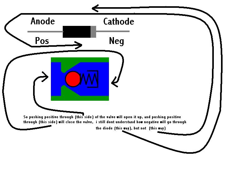
I get confused on diodes too, it helps to only think of it flowing positive. Positive flows from the anode to the cathode (strip side), The door trigger sees a negative, so positive has to flow from the alarm to the door wire. When the door is opened the power goes from the alarm to ground making the wire a ground.
Am I close?
Posted By: i am an idiot
Date Posted: November 01, 2008 at 6:58 PM
What kind of vehicle? Does the vehicle have 4 seperate door open indicators on the dash of the vehicle? If so the reason for the diode isolation is to keep the door open indicators working properly. The diode is a directional device, if it is installed backwards the signal from the pinswitch will not reach the alarm. The link I posted earlier has the 4 pictures of the diodes that show which way a particular voltage will or will not flow through the diode.
Posted By: chadstrawn
Date Posted: November 01, 2008 at 7:18 PM
what i am trying to say is the alarm has a negative door trigger input, and i have to put a diode on each door trigger in the BCM of an impala, but i understand that a diode flows positive to neg, anode to cathode, but i am confused on how when u need to send a negative output to the alarm u have to have the diode looking like this
this end is negative trigger from BCM when door opens---------|<-----------this is the door trigger input to the alarm
so this means, if u are sending a ground signal to the alarm, u have to have the diode opposite to what u would normally put it( --------->|-------- )
its just so confusing trying to learn new things
Posted By: chadstrawn
Date Posted: November 01, 2008 at 7:20 PM
reax222 wrote:
I get confused on diodes too, it helps to only think of it flowing positive. Positive flows from the anode to the cathode (strip side), The door trigger sees a negative, so positive has to flow from the alarm to the door wire. When the door is opened the power goes from the alarm to ground making the wire a ground.
Am I close?
this kinda makes sense but doesnt at the same time lol :P
Posted By: i am an idiot
Date Posted: November 01, 2008 at 7:24 PM
Third picture down shows which way negative voltage travels through the diode. When you put the diode in the other direction, you must have positive voltage traveling through it. Positive voltage flows in the opposite direction. The ( - ) indicates negative voltage applied to that point. The output/no output on the other end indicates whether or not the voltage goes through the diode. 
Posted By: chadstrawn
Date Posted: November 01, 2008 at 7:41 PM
i am an idiot wrote:
Third picture down shows which way negative voltage travels through the diode. When you put the diode in the other direction, you must have positive voltage traveling through it. Positive voltage flows in the opposite direction.
ty i seen this but i was hoping i could get an answer telling me why this works this way, doesnt make sense to me lol maybe i have been told by u guys, i must not be reading what u guys are writing right lol
Posted By: i am an idiot
Date Posted: November 01, 2008 at 7:46 PM
I added a line to my last post after you read it. It may help explain the pictures. https://en.wikipedia.org/wiki/Diode
Posted By: chadstrawn
Date Posted: November 01, 2008 at 7:55 PM
i am an idiot wrote:
I added a line to my last post after you read it. It may help explain the pictures. https://en.wikipedia.org/wiki/Diode
i still dont understand how /why , that if u want a negative signal to pass through a diode u cant do anode to cathode, u have to do cathode to anode for it to pass thru, just isnt making sense to me, sry i am probably annoying most of u lol
Posted By: i am an idiot
Date Posted: November 01, 2008 at 7:59 PM
Posted By: chadstrawn
Date Posted: November 01, 2008 at 8:01 PM
[QUOTE=i am an idiot]Do you know what a check valve does? [/QUOTE
i have a basic idea, but plz explain]
Posted By: i am an idiot
Date Posted: November 01, 2008 at 8:02 PM
Once again I edited my last post after you read it.
Posted By: chadstrawn
Date Posted: November 01, 2008 at 8:33 PM
i am an idiot wrote:
Once again I edited my last post after you read it.
Posted By: mikvot
Date Posted: November 01, 2008 at 9:25 PM
Here ya go man.... I'm like you, I know how they work in my applications...but didn't know they work internally. This should answer your question.
https://www.howstuffworks.com/diode.htm
-------------
Posted By: chadstrawn
Date Posted: November 05, 2008 at 9:46 PM
 ok so anyone else that didnt understand what i didnt understand, i have done some research and have come to a conclusion, i asked my college teacher ELECTRON THEORY Current flows from negative to positive, current flows thru a diode from cathode to anode so the red arrows above are conventional(positive to negative) and the black arrows are electron theory(negative to positive), in my opinion, electron theory makes things so much easier to understand. so as long as u have the most negative side of the circuit on the cathode side current will flow,as soon as u have more positive on the cathode side , no current will flow, its so simple now
Posted By: i am an idiot
Date Posted: November 05, 2008 at 9:51 PM
i am an idiot wrote:
https://www.the12volt.com/diodes/diodes.asp
Copied and pasted from the top of the above page.
1. Cathode (side with the stripe)
2. Anode (side without the stripe)
3. Anytime the cathode is more positive than the anode, no current will flow.
Posted By: howie ll
Date Posted: November 06, 2008 at 12:48 AM
Start with basics; having found the door contact wire, open a second door and shut the first, if your meter shows door open still, you won't need diodes and so on for all 4 or 5 doors. Secondly if your domelight goes out immediately on closing driver's door same again. If the above isn't true then the door contacts (called pin switches) are on separate circuits, eg to do with key sense, door open warnings on instrument panel etc. Thus you would connect to each one and then join together via diodes. With few exceptions these door contacts are negative going or the wire goes to ground on opening, thus band towards your alarm, what you've done is to prevent any false signals going back to the car and messing up processors etc. The second adaptation is where the BCM like on nearly all newer cars "goes to sleep" to conserve juice. These units will send a self check pulse around the car at various times often once an hour, causing your alarm to trigger, thus use blocking diodes, the famous DEI 1076. Think current flow, pos to neg, band from source, block pos, reverse band, I know it's hard to explain unless you can picture the circuit intuitively in your mind.
Posted By: chriswallace187
Date Posted: November 11, 2008 at 3:45 AM
Chad, judging by your earlier post I think you've misjudged which way the current goes on the door trigger wires to the BCM.
The (-) door triggers are inputs to the BCM, not outputs(it uses them to determine the outputs for domelight and other stuff). The purpose of isolating diodes when connecting an aftermarket alarm to separate door triggers is twofold:
1. To keep the door triggers separated from each other.
2. On some vehicles, to isolate the aftermarket alarm from random voltage changes inside the BCM which tend to send enough of a ground to the alarm's door trigger input to set it off.
-------------
C Renner's Auto Electronix
My service is cheap, quick, and good - pick any two
|