rs 1000 in 2001 chevrolet silverado
Printed From: the12volt.com
Forum Name: Car Security and Convenience
Forum Discription: Car Alarms, Keyless Entries, Remote Starters, Immobilizer Bypasses, Sensors, Door Locks, Window Modules, Heated Mirrors, Heated Seats, etc.
URL: https://www.the12volt.com/installbay/forum_posts.asp?tid=109566
Printed Date: March 30, 2026 at 3:46 AM
Topic: rs 1000 in 2001 chevrolet silverado
Posted By: bertleaf
Subject: rs 1000 in 2001 chevrolet silverado
Date Posted: December 08, 2008 at 12:37 AM
Hi,
This my first remote start/alarm install so I'm going to need some help throughout the process. I want to start this coming weekend but I need to straighten out some things first.
I decided to go with the relay and resistor bypass as I don't have any more money for a module. I found this diagram somewhere (not sure where, all credit to the original author).
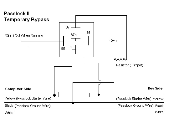
But I am a little confused as to where my starter wires from the remote unit go. So if someone could point me in the right direction, it would be much appreciated.
Truck: 2001 Chevy Silverado LT 5.3L
Wiring info from the install manual.
H1:
Violet - Starter output (this wire wants +12v when ignition is in start only and no voltage when in any other position)
Red (2 wires connected together) - +12v Power input (do i need to seperate these or in there only one wire in the truck to hook it up to?)
Yellow - Ignition 1 ( wants 12 volts when in run or start)
Pink - Ignition 2 ( same as yellow but some vehicles need 2, do I need this one?)
Brown - Accessory ( I understand this connects to orange wire in truck?)
H10:
Yellow - (-)200mA Ignition 3 output ( I think this goes to pin 85 on the relay?)
The thing that confusing me is I don't where the wires from H1 go when using the resistor bypass. So if someone could explain where one goes and also where the ones from the relay go, that would be very appreciated.
Thanks,
Bertleaf
Replies:
Posted By: bertleaf
Date Posted: December 09, 2008 at 7:52 PM
I did some more research and reading around and got mostly cleared up on this one I think. The bypass and ignition wires are actually separate.
Wire on Remote start | Wire in truck
-----------------------------------------------
Violet | Yellow (+)
Red | Red (+)
Red | Red (+)
Yellow | Pink (+)
Pink | White (+)
Brown | Orange (+)
H10: Yellow | Pin 85 on bypass relay
I still have a few questions:
1. Does anyone care to confirm the above information?
2. What would be a good place for a +12v source for pin 86 on the bypass relay? Would one of the red ignition wires work?
3. I have a 30/40A 12V relay that came with the remote starter. Will that work as the bypass relay?
4. Should I diode isolate any of the wires in the bypass circuit or even any of the connections made to the ignition wires?
Thanks and sorry about all the questions but I'm new.
Bertleaf
Posted By: ckeeler
Date Posted: December 09, 2008 at 8:40 PM
1. the info is true, but......Always test yor wires using a DMM 2.the red wires are fine to use for this, thats what i would use. i also fuse mine. you might also do this. its a good idea. 3.that relay is just what you need. 4.you dont need to diode isolate any of those wires.
Posted By: bertleaf
Date Posted: December 09, 2008 at 9:31 PM
Thanks for the reply.
So you would just hook pin 86 up to either (not both) of the red wires?
What size fuse would be good for this?
Both wires have a fuse holder and 20 amp fuse before the enter the remote unit's brain. I'm assuming you mean yet another fuse holder and fuse, that is in the wire going to pin 86.
Posted By: ckeeler
Date Posted: December 09, 2008 at 10:11 PM
yes, another fuse for the wire going to term 86 on the relay. either wire is fine. and use no larger than an 10a fuse
Posted By: bertleaf
Date Posted: December 09, 2008 at 10:28 PM
Thank You ckeeler.
I am stuck on how to do the doors. I've tried searching but it seems that every post I end up at uses some sort of module and again, I didn't budget for any extra parts so I would like to do it without if possible.
Is it possible to just tap into different wires?
Does anyone have any links or diagrams handy that could get me started with this? Or does anyone know and can explain?
There are a number of wires on the remote start unit which can be used for doors but for most it says you may need them, but you may not so I am not sure where to even start.
Any info you got is helpful, I need a place to start looking, thanks.
Posted By: chriswallace187
Date Posted: December 10, 2008 at 12:34 AM
The lock and unlock wires on the '01 Silverado are low current positive trigger at the BCM - light blue and white respectively...what kind of outputs does your RS1000 have?
The doorlocks on Silverados and other full-size GM trucks didn't require a data module until '03 model year.
-------------
C Renner's Auto Electronix
My service is cheap, quick, and good - pick any two
Posted By: bertleaf
Date Posted: December 10, 2008 at 10:47 AM
Are lock and rearm and unlock and disarm factory security considered the same thing?
The unit has the following wires.
H10/16 violet wire - Positive door switch sensing input (zone 3)
This wire is the positive trigger input wire for positive door pin switch. This wire is connection for "positive" type factory door pins. Locate the "common wire"for all door pins and make the connection of the violet here.
H10/17 Green wire - negative door switch sensing unit input (zone 3)
This wire is the ground trigger input wire for negative door pin switch. This wire is connection for "grounding" type factory door pins locate the "common wire" that connects the door pin switches. Make the connection of the green wire here.
H10/3 Pink wire - (-) 200mA Programmamble Output
This one can be programmed as either:
2 Steps Unlock Output or
Factory Security Disarm Signal Output or
Start Status (Shock Sensor By-Pass Control) Output
H10/8 Brown wire - 200mA Pprogrammable Output
Factory Security Rearm Signal Output - This wire will supply a pulse whenever the remote start times out or is shut down using the transmitter and remote door locking.
Posted By: chriswallace187
Date Posted: December 10, 2008 at 1:33 PM
No they're not at all the same. None of those wires, the pink H10/3 excepted, is specifically going to operate doorlocks.
The first two are inputs to let the alarm know when a door is opened so that it triggers. The pink is only designed to unlock the passenger doors on the second press of the button if you program it that way.
There absolutely has to be some other connector on your alarm with lock/unlock wires, if they are saying a wire can be programmed for 2nd unlock. Who's the manufacturer of this RS1000?
-------------
C Renner's Auto Electronix
My service is cheap, quick, and good - pick any two
Posted By: bertleaf
Date Posted: December 11, 2008 at 1:54 AM
The brand is Autopage. Autopage RS-1000
I saw the first two were inputs but I looked through the install manual twice and couldn't find anything, maybe I'm just missing something really obvious. I was not able to find a copy of the manual online for you to have a look.
Posted By: bertleaf
Date Posted: December 11, 2008 at 1:59 AM
ahhh.... found it. It is a seperate harness for the locks and I was overlooking it. Sorry about that.
H7:
Blue Wire - (-)Unlock Pulse / (+)Lock Pulse
Red Wire - Not used
Green Wire - (+)Unlock Pulse / (-)Lock Pulse
Posted By: chriswallace187
Date Posted: December 11, 2008 at 2:04 AM
There absolutely has to be...I'd put money on it if I could. If there's a back page of the install manual which just has the wire pinouts, that would explain a lot.
Does your RS by chance have a 3-pin white H6 plug?
-------------
C Renner's Auto Electronix
My service is cheap, quick, and good - pick any two
Posted By: bertleaf
Date Posted: December 11, 2008 at 2:28 AM
There is, I think you missed my last post, first post on page two
Posted By: chriswallace187
Date Posted: December 11, 2008 at 10:25 AM
yep...typed it up at the same time you were posting judging by the clock there.
-------------
C Renner's Auto Electronix
My service is cheap, quick, and good - pick any two
Posted By: bertleaf
Date Posted: December 12, 2008 at 3:21 AM
Thanks for that information chriswallace187. So if I have it right, the blue wire from H7 would go to the light blue at the BCM and the green on the unit to the white at the BCM.
A few other questions.
1. Where would I hook up the input sensing wire for door locks? And since this is positive trigger, I would use H10/16 and not use H10/17 at all, right?
2. Factory arm and rearm, is that just what sets off the horn when you open the door without using the electric locks or key doohickey? Do I even need this since I have a security system in the the r/s? From information I have read else where I think I do need it because it is always mentioned but I'm still not clear on what exactly it is.
3. On the relay that came with the r/s, there is a diode across pin 86 and 85. I read here somewhere that this was to prevent voltage spikes or something like that. Do I want to do this to all the relays I'll be using or does it not work in all cases or is it just not required?
4. Any recommendations on locations to mount the brain and the shock/glass sensor?
5. Is soldering the best way to connect? Doesn't it crack from temperature changes? Would butt connectors be OK.
Sorry for all the questions but I didn't know there would be quite this much involved or that I know so little.
Posted By: chriswallace187
Date Posted: December 12, 2008 at 8:38 PM
bertleaf wrote:
Thanks for that information chriswallace187. So if I have it right, the blue wire from H7 would go to the light blue at the BCM and the green on the unit to the white at the BCM.
A few other questions.
1. Where would I hook up the input sensing wire for door locks? And since this is positive trigger, I would use H10/16 and not use H10/17 at all, right?
Right on with the lock output wires.
As far as the "door inputs" a bit of clarification - they are used for the alarm features, and have nothing whatsoever to do with the operation of the power locks, which are operated as a keyless entry feature. What the "door sensing input" tells the RS-1000 is whether or not any doors are opened, which it uses for alarm triggering as well as possibly for changing the programmed settings.
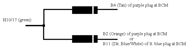
You should use the H10/17 wire, since the "door open" switches are negative. Also, the truck has separate door triggers for the left and right door - see here for the specific wire colors/locations. You should diode isolate your connections to those wires; you can follow the link to "Mobile Electronics Basics: Diodes" on the left of this site, or just post back for more info on that subject.
bertleaf wrote:
2. Factory arm and rearm, is that just what sets off the horn when you open the door without using the electric locks or key doohickey? Do I even need this since I have a security system in the the r/s? From information I have read else where I think I do need it because it is always mentioned but I'm still not clear on what exactly it is.
It depends - I'd at least connect the factory disarm because it's just one wire, right at the BCM where you're making other connections anyway. Handy when the factory alarm's been inadvertently armed (if you lock the doors, using the power lock switch or your RS-1000 remote, with a door opened, this will arm the factory alarm).
Factory re-arm is redundant since you've got aftermarket security. It's also slightly more complicated to connect. I'd say don't worry about it.
bertleaf wrote:
3. On the relay that came with the r/s, there is a diode across pin 86 and 85. I read here somewhere that this was to prevent voltage spikes or something like that. Do I want to do this to all the relays I'll be using or does it not work in all cases or is it just not required?
It doesn't hurt anything to always use a suppression diode such as that. I generally don't bother because I think most of the equipment I install is not that sensitive.
bertleaf wrote:
4. Any recommendations on locations to mount the brain and the shock/glass sensor?
Brain - behind the instrument cluster or radio/HVAC controls may work if there's room. Make your harnesses look as factory as possible(taped and run alongside the factory wiring is good).
Shock and glass sensor mounting locations are according to the manufacturer of the sensor. I won't comment because I've never done AutoPage
bertleaf wrote:
5. Is soldering the best way to connect? Doesn't it crack from temperature changes? Would butt connectors be OK.
I like soldering personally, and it doesn't crack when done properly(it's used internally in each of the several dozen OEM control modules on your truck). You may be thinking of a cold solder joint? I'm not sure.
There are several posts on this site about which is better, but both are acceptable when done correctly. Make sure the connections are thoroughly concealed whichever way you go.
bertleaf wrote:
Sorry for all the questions but I didn't know there would be quite this much involved or that I know so little.
Your honesty is commendable. There are some people who come in here and think they're entitled to free and quick help and act accordingly. I'm happy to help others get things done. It takes lots of practice to do this stuff very quickly in any case. ------------- C Renner's Auto Electronix
My service is cheap, quick, and good - pick any two
Posted By: bertleaf
Date Posted: December 13, 2008 at 1:58 AM
Thank You for all that. I do appreciate that you are taking this much time to help me out as I'm sure you are pretty busy with getting ready for the holidays and winter etc.
So I checked out the links and came up with this:
The H10/3 pink wire is programmable as a factory disarm output. I don't really care for the two-step unlock but I'm not sure if I need the shock sensor bypass output. I don't see where I would use it as the shock sensor has it's own harness with no open wires. Maybe it is for a separate or another shock sensor? The manual just says the wire has a signal 4 seconds before starting and while running, one would assume the unit should do this bypass automatically for it's own shock sensor since a running vehicle is certainly going to vibrate. If that is the case then I will program it to be a factory disarm output and I believe it hooks it up to the lt. green at purple BCM plug.
The wire diagram you linked to has a lock motor, unlock motor, and disarm defeat. I'm not sure what these are, is there any thing else they might be known as? I don't remember seeing them in the install manual. Or maybe I don't need them at all.
I also had a question about the parking light hookups but I don't have my manual with me so I'll have to get that in later.
Posted By: chriswallace187
Date Posted: December 13, 2008 at 2:24 AM
Right on again with the diode layout.
Lock motor, unlock motor, and disarm defeat are specifically included by Directed Electronics (the company whose wiring info is copied/pasted there) because they are used for an OEM keyless upgrade alarm install.
Apart from that, I've used the lock motor wire to have a factory keyless entry system start the car remotely with 3 presses of the lock button; I've used the unlock motor wire to do progressive unlocking.
-------------
C Renner's Auto Electronix
My service is cheap, quick, and good - pick any two
Posted By: tedmond
Date Posted: December 13, 2008 at 5:43 AM
bertleaf wrote:
Sorry for all the questions but I didn't know there would be quite this much involved or that I know so little.
[QUOTE Chriswallace]
Your honesty is commendable. There are some people who come in here and think they're entitled to free and quick help and act accordingly. I'm happy to help others get things done. It takes lots of practice to do this stuff very quickly in any case.
i agree on that !
Posted By: joch1314
Date Posted: December 13, 2008 at 12:58 PM
ChrisWallace187 pretty much has you taken care of, but one thing i'd like to chime in with is the concealing of the brain. I'm not sure how big your alarm brain is, but in those vehicles I like mounting the brain behind the very left a/c vent. The vent is together with the light switch and dimmer and that whole piece just pops out. Once you get that out there is plenty of room to place your brain. I just did a 2000 GMC sierra(same truck) two days ago and it was a breeze. Really easy to route your wires to the ignition harness too. One thing that i found odd was the starter wire....most starter wires are the same gauge as the other ignition wires but the yellow starter wire in this case was like 18 gauge. Also, you'll see two wires in yellow loom plugged in the bottom of the steering column. STAY AWAY FROM THOSE WIRES!!! those wires are for the airbag...and any wires in yellow loom, for future reference, are airbag wires.
-------------
...half of the truth can be worse than a lie. <----Roger Russell said that..
Posted By: jrilla
Date Posted: December 13, 2008 at 4:41 PM
I have to say this. I just realized it has been six years since I found this site, and I don't visit as often as I did when I first started, but when I saw the passlock bypass diagram you posted, I had a good, loud laugh and I had to let you know that I drew that diagram back when I first found this site, and I posted on this free webserver site and I can't believe anyone ever found it.
Good luck with the install.
Posted By: bertleaf
Date Posted: December 13, 2008 at 5:44 PM
joch1314 wrote:
ChrisWallace187 pretty much has you taken care of, but one thing i'd like to chime in with is the concealing of the brain. I'm not sure how big your alarm brain is, but in those vehicles I like mounting the brain behind the very left a/c vent. The vent is together with the light switch and dimmer and that whole piece just pops out. Once you get that out there is plenty of room to place your brain. I just did a 2000 GMC sierra(same truck) two days ago and it was a breeze. Really easy to route your wires to the ignition harness too. One thing that i found odd was the starter wire....most starter wires are the same gauge as the other ignition wires but the yellow starter wire in this case was like 18 gauge.
Thanks for that, and ChrisWallace187 has indeed been a great help.
I frequently see installs mentioning that the brain is behind the instrument cluster, ChrisWallace187 mentioned that place as well but this brain won't fit there especially once all the harnesses are plugged in and I haven't checked behind the Hvac for sure but I don't recall the space behind there being deep or high enough. So I will check out the space behind the vent like you said.
joch1314 wrote:
Also, you'll see two wires in yellow loom plugged in the bottom of the steering column.
Are these positive or negative trigger? Should put them on a time delay and it's sure to surprise any would-be thief.
Posted By: bertleaf
Date Posted: December 13, 2008 at 5:50 PM
jrilla wrote:
I have to say this. I just realized it has been six years since I found this site, and I don't visit as often as I did when I first started, but when I saw the passlock bypass diagram you posted, I had a good, loud laugh and I had to let you know that I drew that diagram back when I first found this site, and I posted on this free webserver site and I can't believe anyone ever found it.
Good luck with the install.
That is funny. I'm not even sure where I got that from, I saved it on my computer a few weeks ago.
Well it has certainly been a helpful diagram for me and you can feel good knowing your work from years ago is still helping new guys like me.
Posted By: joch1314
Date Posted: December 13, 2008 at 5:53 PM
not sure...but i think they'll probably be positive trigger.
-------------
...half of the truth can be worse than a lie. <----Roger Russell said that..
Posted By: bertleaf
Date Posted: December 14, 2008 at 5:10 PM
Yeah.... I'll just stay away from them. Thanks for the heads-up.
Well I didn't get too much done on the r/s install but I mounted most of the components and got through the firewall and ran all the wires and some cables for an amp so by the time I had that done and out of the way I was out of time as I had other things planned so I will continue another weekend. In the meantime I would just like to get cleared up on most of the connections.
So as usual I have a few questions again:
1. Since I'm not going to use the factory rearm, I'd like to use H10/8 as the horn output so that it also sounds when the alarm is triggered. The wire supplies a transistorized low current output, and should only be connected to the low current ground output from the vehicle's horn switch. So can I connect it to the black wire in the brown plug at the BCM?
2. Is it best to hook up as tachometer check, timer check, or volt check to see if engine is running?
3. In the programing guide there is something mentioned about passive or active arming. I'm not sure what that means.
Posted By: another-kelly
Date Posted: December 14, 2008 at 8:18 PM
1) yes
2) tachometer
3) active - arms with remote only
passive - arms with remote OR arms after (x) amount of time after the alarm sees the last door shut automatically
Posted By: bertleaf
Date Posted: December 30, 2008 at 5:39 PM
Thanks another-kelly. I've got some more time this week so I'm back at it. H2/1 - RED / white wire - This wire is the input to the flashing parking light relay. The connection of the this wire will determine the output polarity of the flashing light relay. IF the vehicle has +12v switched parking lights, you don't need to connect this wire as it is already connected to a +12v source. If the parking lights are ground switched, cut the wire and connect it to chassis ground. H2/2 - white wire - (+12V 10A output) - connect this wire to the parking light wire coming from the headlight switch. do not connect it to the dashboard lighting dimmer switch as the dimmer will be damaged. The limitation of this wire is 10 amp max, do not exceed this limit or damage to the alarm and parking relay will result. 1) The way I understand this vehicle has +12v switched parking lights at the brown wire in the light blue plug at the BCM. Can I connect the white wire to the brown wire at the BCM? It shouldn't ever pull 10amps from there? 2) Since they are positive switched parking lights I suppose I leave the RED / white wire connected to the red wire and hook it up to a constant +12V. 3) Speaking of constant +12v, when I was connecting H1 to the ignition wires, I found only one thick red wire, I tested ti with a DMM and it is constant +12, but I need two, I did see a thin red wire and tested it and it also had +12v with the ignition off and key removed. So is this the second +12v wire(the one with the red clip)? I just wasn't sure because it was a smaller wire compared to the other one(with the green clip) and compared to the wire it connects to in H1. 4) Can I connect all the wires that need +12v all the time to the red ignition wires? Probably to the bigger one? 
Thanks
Posted By: joch1314
Date Posted: December 30, 2008 at 6:25 PM
I think that the RED / white wire also has 12V+ constant...Try testing that, but i don't see any problems hooking other wires (as long as they're not thicker gauge remote start wires) to the red wire you mentioned. Why not get the parking light wire at the switch...it should be light blue (+). Make sure you hook up both ignition wires (pink and white).
-------------
...half of the truth can be worse than a lie. <----Roger Russell said that..
Posted By: bertleaf
Date Posted: December 30, 2008 at 8:09 PM
Thanks joch1314. I did check the fat RED / white but I didn't get anything, I'll try agian tomorrow, maybe I misssed. The reason I wondered about hooking the parking wire at the BCM is because I thought it might be easier and I wouldn't have to worry about how much current it draws but I suposse the switch is right where I am working and I could always use a fuse.
Posted By: chriswallace187
Date Posted: December 30, 2008 at 10:11 PM
The brown wire will draw the same current whether or not you connect it at the BCM or the switch - I think the only reason it goes to the BCM is as a signal input for the "lights-on" reminder chimes and such. Unless your truck's got extra lighting (running boards, cab markers, etc.) or a trailer connector wired directly to that parking light circuit (I believe that '99-up Silverado has a separate fuse for the factory trailer wiring), you should be allright with the direct connection. If it blows the fuse on the RED / white, you can always put in a relay for the parking lights. The angry warning about relay/control module damage only applies to idiots who blow that 10A fuse and then replace it with a 20A instead of wiring in a relay - and you don't strike me as the type :-). Also I agree with joch1314 on the RED / white at the harness being 12V constant. Basically all GM vehicles with heavy gauge ign. switch wires have red and RED / white, or 2 separate red as their constant 12V feeds. ------------- C Renner's Auto Electronix
My service is cheap, quick, and good - pick any two
Posted By: CutDog504
Date Posted: December 31, 2008 at 12:01 AM
I'd like to chime in on this with a few tips. I've installed a autopage rs660 (VERY similar to yours) on my 01 suburban. I agree with joch1314 on placement of the brain, thats where I put mine. Just firmy pul at the whole corner panel with the headlight switch and AC vent and that lil storage pocket. That whole section is held in with clips and you can pop it straight out and see a huge empty void behind there. Looking up from underneath the dash by the brake pedal, you can't see this area. It was a tight squeeze working the brain in thru the opening, but once I got it past that AC duct, its got plenty of room back there. Kind of a pain to get it secured with some zip ties tho.
On another note, the autopage alarms have the parking light wire fused at the power wire (I think it was RED / white) that supplies power to the internal parking light relay. But there is no fuse on the white wire that connects to the parking light wire in the vehicle. You should add a 10 amp fuse to this white wire. I didn't on mine and I wish I had. I frequently tow a trailer, and have remote started my truck with the trailer connected. So not only was was white wire powering my parking lights, but all the running lights on my trailer. It eventually melted that white wire and caused me problems. I finally figured it all out(after days of digging into my dash and probing) and had to replace that section of wire. So I HIGHLY reccommend you fuse that white parking light wire, especially in you use your truck to tow a trailer.
Posted By: bertleaf
Date Posted: December 31, 2008 at 4:09 PM
Thanks guys. I'm not sure what I did yesterday but the RED / white in the truck does definately have constant +12v. How would I test for the factory disarm wire, I tried the lt. green in the purple plug but I just get constant power and it doesn't seem to change when I unlock with the remote or the switch. CutDog504 where did you end up putting your shock sensor? My manual doesn't say much about it.
Posted By: chriswallace187
Date Posted: December 31, 2008 at 6:16 PM
Light green in the purple plug should go to ground when you turn the key to unlock in the driver's door cylinder. The power lock switch and remote don't affect it.
-------------
C Renner's Auto Electronix
My service is cheap, quick, and good - pick any two
Posted By: CutDog504
Date Posted: January 01, 2009 at 9:19 AM
I beleive I just zip tied it around a wire harness under the dash, but its still accessible if i lok up from the brake pedal area. That way I can fine tune the sensitivity if I ever choose to, without having to tear apart my dash.
Posted By: another-kelly
Date Posted: January 01, 2009 at 9:21 PM
bertleaf wrote:
How would I test for the factory disarm wire, I tried the lt. green in the purple plug but I just get constant power and it doesn't seem to change when I unlock with the remote or the switch.
test it by unlocking with the key in the drivers door
Posted By: CutDog504
Date Posted: January 02, 2009 at 7:45 AM
Also, to test the factory disarm wire, the drivers door has to be closed. OR the latch has to be closed so that the BCM thinks the door is closed.
Posted By: bertleaf
Date Posted: January 03, 2009 at 9:49 PM
Thanks guys, that worked. I just assumed that it disarms the factory security when you unlock with the switch or the remote but i guess the circuitry for that is elsewhere. I've been kinda busy but I got everything hooked up and it locks, unlocks, arms, disarms, triggers, starts, and shuts off as expected so I'm happy with it. I just gotta clean up all the wires tomorrow and reassemble the interior of the truck.
Thanks everyone for your help, probably wouldn't have happened without. Chriswallace187 I have found your service to be cheap, quick, and good - all three.
Posted By: chriswallace187
Date Posted: January 04, 2009 at 5:01 AM
bertleaf wrote:
Chriswallace187 I have found your service to be cheap, quick, and good - all three.
Crap...I better start charging for this stuff.  ------------- C Renner's Auto Electronix
My service is cheap, quick, and good - pick any two
Posted By: bertleaf
Date Posted: January 18, 2009 at 2:05 PM
Well it's been a few weeks now and everything is working dandy, well mostly.
I think I must have done something wrong with the Passlock bypass. It starts fine when using the remote but when I put the key in the ignition and turn it to on and then hit the brake, the security light comes on and stays on till I shut the truck off and start again. When using the key to start it works normally. Everything works fine but as I understand the security light shouldn't come on at all if the bypass is done correctly?
Just another quick question, is it possible to add more sirens to this system? I recently saw sirens for a few dollars at a store that look like they are made by the same company that made the one that came with my alarm. They come in the same white box with no name or anything and they look identical except for a few different numbers on the stickers(6-tone) and the one with the alarm is 1-tone. I'm not sure the wire from the unit supplies enough power for more sirens and I think the siren needs some sort of driver (or whatever it's called) because just giving it 12volts does nothing.
|