I am about to install an Ultra Start 1280 in a 1998 Altima GXE. Car has no factory alarm system and I think the doors are electrically locked/unlocked when key is turned in door. What is the best method/location for connecting door lock/unlock.
I have seen a wiring sheet that says the ACCESSORY /HEATER circuit must be isolated with relay to prevent starter run on? I have also seen a wiring sheet that did not mention this. Does anyone out there know first hand if any special isolation on this circuit is necessary. Thanks for your time.
Wayne
-------------
Ajusted
There is probably a post on that subject in this forum under vehicle wiring, you could look at that first.
Well I did numerous searches on this site in all forums and did not find the answer that is why I was looking for someone that has experience with this install. Below is a link to a diagram I located that shows a relay wired for this isolation. On that diagram I do not fully understand the purpose of connecting relay contact 30 and the accessory output wire from the remote starter to the same end of the cut wire. Or is this isolation even necessary?
https://64.85.6.129/extrainfo/diagrams/14301_ALTIMA_NISSAN%20ACCESSORY%20ISOLATION%20CIRCUIT.pdf
-------------
Ajusted
Ok, the reason you need to do this is because of the design of the ignition switch the RS will backfeed voltage thru it to the starter wire and hold the starter on. Because of this you must add the relay as described in the diagram with one exception. The yellow wire makes no sense as it gives the accessory wire voltage whenever the RS is activated instead of just accessory. Leave 87 disconnected. As for contact 30, think of it like a starter kill relay but instead of killing the starter you are killing the accessory wire whenever the RS is on. Follow the diagram and you will be fine.
As for the locks, go to the Smart Entrance Control module. When you remove the knee bolster look to the right of the steering column and you will see it. LOck is gray, unlock is purple. You can also get all your triggers, lights, horn at this module...
-------------
Mike M2
Tech Manager
CS Dealer Services
Yes this is correct. You get the same ending whether you connect to 87 or to 30.....
-------------
Mike M2
Tech Manager
CS Dealer Services
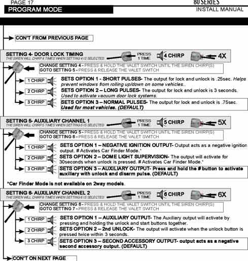
Ok one more question about this install. The Ultra Start 1280 installation manual gives the following regarding programing an output for additional (-)ignition output. The description is confusing to me. From the manual as depicted below, Setting 5 - Auxiliary Channel 1, Option 1 states:
"Output acts as a negative ignition output. # Activates car finder mode."
If the RS output is providing (-) ignition output anytime the RS is active how can this output provide any other function at the same time. For example if the RS has car running and thus the RS is providing (-) ignition for my relay what happens when the # button is pushed on the remote control.
The first statement below is a description of the Auxiliary output from the remote installation manual and the second is the programming instruction for this output. This is NOT a 2 way model:
WHT/VIOLET Auxiliary Output 1/ Programmable Output Auxiliary output when the # button is held. Programmable to (-)Ignition/ Car Finder and Dome Light Supervision with Car Finder. (Car Finder and Auxiliary 1 are not available on 2way models)
-------------
Ajusted
Hopefully someone else here can help as i am not familiar with Ultrastart. I'm not sure what car finder mode even is...
-------------
Mike M2
Tech Manager
CS Dealer Services