2009 Honda CR-V Remote Start And Wiring
Printed From: the12volt.com
Forum Name: Car Security and Convenience
Forum Discription: Car Alarms, Keyless Entries, Remote Starters, Immobilizer Bypasses, Sensors, Door Locks, Window Modules, Heated Mirrors, Heated Seats, etc.
URL: https://www.the12volt.com/installbay/forum_posts.asp?tid=110248
Printed Date: May 10, 2026 at 9:44 AM
Topic: 2009 Honda CR-V Remote Start And Wiring
Posted By: cpgoose
Subject: 2009 Honda CR-V Remote Start And Wiring
Date Posted: January 01, 2009 at 11:26 PM
Howdy folks...good to be back :) I've been gone for a while, but it's cool to see a lot of the same names around still.
I recently bought a 2009 Honda CR-V, and I was curious if anyone has the wiring diagram because I want to install a remote starter. It came with the factory alarm, so I'm sure I'll need additional parts to install it. I've done about 5 or 6 remote starters, and none of the cars had real alarms in them to begin with. So...any ideas would be great, too (like bypasses, transponders, etc).
Thanks!
Replies:
Posted By: dtk1
Date Posted: January 02, 2009 at 1:41 AM
the info I have is for an 08 but am sure its the same as an 09 for the bypass you can use a KEY-OVERRIDE-ALL made by fortin electronics HERE
2008 Honda CRV
Item Wire Color Polarity Wire Location
12 Volts white (50A) + ignition switch, brown 6 pin plug, pin 3
Second 12 Volts N/A
Starter yellow + ignition switch, brown 6 pin plug, pin 1
Second Starter N/A
Ignition blue + ignition switch, brown 6 pin plug, pin 6
Second Ignition N/A
Third Ignition N/A
Accessory orange + ignition switch, brown 6 pin plug, pin 4
Second Accessory red + ignition switch, brown 6 pin plug, pin 5
Third Accessory N/A
Keysense gray - ignition key cylinder, green 7 pin plug, pin 1
Data Bus green (data), lt. blue (ignition), brown (ground) data Immobilizer Module, white 7 pin plug, pins 3, 2, and 7
The Immobilizer Module is around the ignition key cylinder.
Can Bus High N/A
Can Bus Low N/A
Can Bus Sw pink data Immobilizer Module, white 7 pin plug, pin 4
The Immobilizer Module is around the ignition key cylinder. Also found at the fuse box, rear, 16 pin plug, pin 6.
Power Lock blue - driver kick or MICU, green 34 pin plug, pin 28
The MICU (Multiplex Integrated Control Unit) is attached to the back of the fuse box, under the driver side dash.
Power Unlock gray - driver kick or MICU, green 34 pin plug, pin 27
The MICU (Multiplex Integrated Control Unit) is attached to the back of the fuse box, under the driver side dash.
Lock Motor pink 5 wire driver kick or fuse box, green 42 pin plug, pin 21
Driver Unlock Motor gray 5 wire driver kick or fuse box, rear, 14 pin plug, pin 13
Passenger Unlock Motor yellow 5 wire driver kick or fuse box, green 42 pin plug, pin 14
Parking Lights (-) blue - headlight switch, 12 pin plug, pin 11
Also found at the MICU, green 20 pin plug, pin 13. The MICU (Multiplex Integrated Control Unit) is attached to the back of the fuse box, under the driver side dash.
Parking Lights (+) red + driver kick or fuse box, rear, 10 pin plug, pin 3
Hazards purple + hazard switch, green 6 pin plug, pin 5
Turn Signal (Left) orange + driver kick or fuse box, green 42 pin plug, pin 40
Turn Signal (Right) brown + driver kick or fuse box, green 42 pin plug, pin 39
Headlight pink - headlight switch, 12 pin plug, pin 10
Also found at the MICU, green 20 pin plug, pin 11. The MICU (Multiplex Integrated Control Unit) is attached to the back of the fuse box, under the driver side dash.
AutoLights N/A
Reverse Light brown + driver kick or fuse box, green 42 pin plug, pin 15
Left Front Door Trigger green - driver kick or fuse box, green 42 pin plug, pin 37
Right Front Door Trigger lt. green - pass kick or fuse box, green 42 pin plug, pin 3
Left Rear Door Trigger white - driver kick or fuse box, green 42 pin plug, pin 17
Right Rear Door Trigger gray - pass kick or fuse box, green 42 pin plug, pin 2
Dome Supervision purple - driver A pillar or fuse box, rear, 8 pin plug, pin 4
Trunk/Hatch Pin pink - driver kick or fuse box, green 42 pin plug, pin 36
Rear Glass Pin N/A
Hood Pin yellow/red to lt. blue - hood pin switch or fuse box, blue 21 pin plug, pin 9
Trunk/Hatch Release white - driver kick or fuse box, green 42 pin plug, pin 13
Meter this wire while opening the hatch from the handle on the rear hatch.
Trunk Release Motor green 5 wire driver kick or fuse box, green 42 pin plug, pin 20
Fuel Door Release N/A
Power Sliding Door (Left) N/A
Power Sliding Door (Right) N/A
Factory Alarm Arm pink - driver kick or MICU, green 34 pin plug, pin 32
The MICU (Multiplex Integrated Control Unit) is attached to the back of the fuse box, under the driver side dash. Meter this wire while turning the key in the driver door key cylinder.
Factory Alarm Disarm brown - driver kick or MICU, green 34 pin plug, pin 31
The MICU (Multiplex Integrated Control Unit) is attached to the back of the fuse box, under the driver side dash. Meter this wire while turning the key in the driver door key cylinder.
Disarm No Unlock see factory alarm disarm
Trunk Alarm Shunt N/A
Tachometer NOT yellow/black ac any fuel injector
Wait to Start N/A
Neutral Safety N/A
Clutch Pedal N/A
Fuel Pump green + driver kick or fuse box, green 42 pin plug, pin 9
Rear Defroster lt. green - latched heater control panel, gray 28 pin plug, pin 20
Mirror Defroster same as rear defroster
Left Front Heated Seat blue + latched driver seat heater switch, white 6 pin plug, pin 3
Right Front Heated Seat red + latched passenger seat heater switch, white 7 pin plug, pin 4
Speed Sense blue ac radio, gray 17 pin plug, pin 13
Brake Wire lt. green + switch or fuse box, green 42 pin plug, pin 34
Parking Brake purple - parking brake switch
Horn Trigger orange - horn switch, yellow 20 pin plug, pin 1
Wipers orange (L), white (H) - wiper switch, 8 pin plug, pins 2 (L) and 4 (H)
Also found at the MICU, green 20 pin plug, pins 10 (L) and 20 (H). The MICU (Multiplex Integrated Control Unit) is attached to the back of the fuse box, under the driver side dash.
Left Front Window (Up/Down) pink - gray A power window master switch, gray 22 pin plug, pins 10, 9
Right Front Window (Up/Down) orange - brown A driver kick, door harness
Left Rear Window (Up/Down) green - purple A driver kick, blue 18 pin plug, pins 10 and 15
Right Rear Window (Up/Down) lt. blue - red A driver kick, door harness
Sun Roof (Open/Close) motor part of module
Sun Roof (Limit/Close) N/A
Memory Seat 1 N/A
Memory Seat 2 N/A
Memory Seat 3 N/A
Radio 12V orange or lt. green + radio, gray 17 pin plug, pin 17
Radio Ground black - radio, gray 17 pin plug, pin 9
Radio Ignition white + radio, gray 17 pin plug, pin 14
Radio Illumination gray (parking lights), red (dimmer) +,- radio, gray 17 pin plug, pins 10 and 1
Factory Amp Turn-on red + radio, gray 20 pin plug, pin 20
Power Antenna N/A
Left Front Speaker (+/-) lt. green - green +,- radio, gray 17 pin plug, pins 12 and 3 or amplifier
If equipped, the amplifier is under the middle of the dash.
Right Front Speaker (+/-) white - yellow +,- radio, gray 17 pin plug, pins 15 and 7 or amplifier
Left Rear Speaker (+/-) gray - brown +,- radio, gray 17 pin plug, pins 11 and 2 or amplifier
Right Rear Speaker (+/-) blue - orange +,- radio, gray 17 pin plug, pins 16 and 8 or amplifier
Center Channel (+/-) N/A
Subwoofer (+/-) pink - blue +,- amplifier under middle of dash
Aux. Audio Input Left (+/-) white - black (common) +,- radio, gray 20 pin plug, pins 13 and 3
Aux. Audio Input Right (+/-) red - black (common) +,- radio, gray 20 pin plug, pins 14 and 3
RSE Video (+/-) N/A
RSE Audio Left (+/-) N/A
RSE Audio Right (+/-) N/A
Satellite Radio 12 Volts orange + XM Receiver, white 14 pin plug, pin 1
The XM Receiver is in the passenger kick.
Satellite Radio Ground lt. blue - XM Receiver, white 14 pin plug, pin 11
Satellite Radio Ignition purple + XM Receiver, white 14 pin plug, pin 2
Satellite Radio Antenna black RF XM Receiver, black 1 pin plug, pin 1
Satellite Audio Left (+/-) green - black +,- XM Receiver, white 14 pin plug, pins 6 and 14
Satellite Audio Right (+/-) red - white +,- XM Receiver, white 14 pin plug, pins 5 and 13
Item Size Depth Location
Headunit irregular center of dash
Left Front Speaker 6.5 left front door
Left Front Tweeter left front dash
Right Front Speaker 6.5 right front door
Right Front Tweeter right front dash
Left Rear Speaker 6.5 left rear door
Left Rear Tweeter N/A
Right Rear Speaker 6.5 right rear door
Right Rear Tweeter N/A
Center Channel N/A
Subwoofer under front passenger seat
Left Front Headrest
Right Front Headrest
Left Rear Headrest
Right Rear Headrest
Satellite Radio Tuner passenger kick
Posted By: cpgoose
Date Posted: January 02, 2009 at 12:11 PM
Excellent, thanks for the info!
Since I'm new the bypass arena, I just want to make sure I have this right. Since the key has a chip in it, the bypass module allows me to remotely start the car without having the key in the car, right?
Do you know what type of system the CRV has? In other words, I see PATS, PASSLOCK, etc.
Oh, and the install instructions you linked me to have a step for installation "with Data Link" or without it. What is Data Link :) If it helps, my CRV doesn't have navigation.
Thanks again!
Posted By: t&t tech
Date Posted: January 02, 2009 at 1:29 PM
how come this guy's member status is gold? no offence cpgoose, anyway, ur cr-v has a transponder immobiliser system, and ur question about the data link, for ur remote start to operate properly, it requires interfacing with the databus system on the vehicle. happy new year by the way.
-------------
Posted By: cpgoose
Date Posted: January 02, 2009 at 1:44 PM
If you're going bust on someone, at least spell the words correctly.
Posted By: t&t tech
Date Posted: January 02, 2009 at 1:54 PM
i said no offence dude, i just find it strange ur questions about the transponder and the data link to be somewhat basic, so i was just wondering how come ur (spelt that way intentionally) status is gold. i humbly apologize if u were offended in any way.
-------------
Posted By: chriswallace187
Date Posted: January 02, 2009 at 4:38 PM
I think my status is silver and that the12volt and other moderators stopped caring about the status indicators a year or two ago. I want an upgrade! 
Perhaps cpgoose posts a lot about audio? Not sure. At any rate -
"Datalink" is a feature of some remote starters which allows them to supply power, ground, and data codes through a 4-pin cable to an interface module. This saves the installer from having to make several wire connections between the RS and the interface module.
Honda just refers to the system as the "Immobilizer Theft-Deterrent System". However if you look at this sticky post on the subject, written by a supremely brilliant contributor to the site, your CR-V's system would be type 3(Transponder). PATS is also a transponder-based system, but it's only found on Ford products. It works the same way in principle.
Using a module like the one recommended above would spare you from having a key in the vehicle during remote start. ------------- C Renner's Auto Electronix
My service is cheap, quick, and good - pick any two
Posted By: t&t tech
Date Posted: January 02, 2009 at 4:43 PM
oh by the way, happy new year chris
-------------
Posted By: chriswallace187
Date Posted: January 02, 2009 at 7:36 PM
You too t&t!
-------------
C Renner's Auto Electronix
My service is cheap, quick, and good - pick any two
Posted By: tedmond
Date Posted: January 02, 2009 at 8:46 PM
i almost have as many post as you chris, i want an upgrade too, afterall i should get some recognition for being the youngest installler on this site.  btw, thanks for the info about the rs. i found in my garage an add on rs unit which i dont even know who made or or where i came from. you got anything that just sends out an aux signal? i just need to trigger that unit. i think its a DEI build but not sure.
Posted By: cpgoose
Date Posted: January 02, 2009 at 10:46 PM
Hey, thanks for the reply Chris...very helpful! I read the other post, too, by the supremely brilliant contributor ;) Thanks, that was good, too. So I guess that bypass module listed above is considered a "vehicle-specific data bypass", right?
Alright, so now I have a better understanding of Data-Link. Depending on which remote starter I pick, is it all the same idea, but with different names? Or do I have to get one that specifically has "Data-Link"?
Are there remote starters now that also have a "data-link" type hookup to the vehicle itself, too? Almost like when you install a headunit and you can use a wire harness so you don't have to make so many connections?
Thanks! (Sorry for all the questions)
Posted By: chriswallace187
Date Posted: January 03, 2009 at 9:41 AM
cpgoose wrote:
So I guess that bypass module listed above is considered a "vehicle-specific data bypass", right?
We are talking vehicle-specific data bypass here, yes.
cpgoose wrote:
Alright, so now I have a better understanding of Data-Link. Depending on which remote starter I pick, is it all the same idea, but with different names? Or do I have to get one that specifically has "Data-Link"?
I'll be honest and say I have no experience at all installing any data link system from any manufacturer with a direct data cable connection. I've done installs using bypasses which have that capability; however I've always just connected the individual wires.
I've done some research for this post and figure I'll have to try using a data cable for an install in the near future. Hopefully another contributor can make up for my lack of knowledge here in this regard.
Data link bypass manufacturers include Bypasskit(owned by Directed Electronics since 2007 sometime), Idatalink, and Fortin. To my knowledge that's all of them, and everyone else selling data bypasses simply rebadges one of those 3 manufacturers' products.
As far as the remote start brands which have the data link capability, the following names seem to pop up on bypass manufacturer websites - Audiovox, AutoPage, Compustar, Directed(Viper/Python), Astrostart, Code Alarm, and several others.
Now for what appears to be the key part, and where I hope someone else can clarify. The interface protocol between the bypass modules and the remote start/alarm host units does NOT appear to be standardized across the industry. All 3 manufacturers appear to use a 4-pin RS232 cable for their data link connections; however RS232 only means that the connection is the same and not necessarily the actual data being transmitted.
In other words, the hardware is compatible; the software may not necessarily be, and anyone looking to use a data link connection for a remote start install needs to be careful to make sure they are buying remote starts and bypasses which can work with each other.
Of course if they don't work data-to-data you always have the option of just connecting the individual wires - but just plugging the cable could definitely save serious time for an installer.
cpgoose wrote:
Are there remote starters now that also have a "data-link" type hookup to the vehicle itself, too? Almost like when you install a headunit and you can use a wire harness so you don't have to make so many connections?
In answer to your last question, as far as a quick connection to the vehicle itself - Bulldog (and possibly others) made a T-harness a few years ago which was supposed to do that. The basic idea was that you'd disconnect the factory ignition switch plug, put one end of the T-harness into each end, and plug the rest into the Bulldog remote starter.
A neat idea in theory, but in practice it wouldn't plug directly into every remote starter they made, added a god-awful amount of wiring to the underdash area, and didn't include ground, brake, parking lights, hood, tach, doorlocks, and other connections.
Bypasskit, whose bypasses I've used more than others, makes a remote start specifically designed for push-to-start late model Nissans, as well as upgrade kits for GM vehicles with OEM remote starters (these add a 2-way remote and longer range antenna), which are much easier to install(3 wires at the diagnostic plug). It's likely that other vehicles will have remote starts like these available in the near future. ------------- C Renner's Auto Electronix
My service is cheap, quick, and good - pick any two
Posted By: loneranger
Date Posted: January 04, 2009 at 5:25 PM
chriswallace187, you hit the nail on the head. This was the type of information I was hoping to get started in my thread. However, it started going south. Appreciated the replies but, because of the structure of my first post, the replies were mainly about my specific vehicle and it's integration options. I tried to explain what the thread was about but, it didn't get across. Thanks for your input here. As a correction, the term "iData Link" is used by Automotive Data Solutions, "Data Link" is used by Fortin Electronic Systems, and "D2D/ED2D" is used by Directed Electronics Canada Inc.
Posted By: cpgoose
Date Posted: January 28, 2009 at 11:48 AM
Ok, I'm still in the process of researching which remote starter to buy (or alarm/rs combo). I've read in a few places that if I just install a RS unit, then the factory FOB won't work anymore to unlock the door. But then if I install an alarm/RS unit, I can use the new remote to unlock the doors.
Does anyone know how to figure this out before I buy?
Oh, and I think I'm pretty much set on buying the Honda-SL3 bypass :)
Posted By: chriswallace187
Date Posted: January 28, 2009 at 12:42 PM
If you want to verify that for yourself, put the key in the ignition, turn to run, and try to operate the factory remote. It will not do anything at that point.
Just to clarify, the addition of a remote start doesn't stop the factory remote from working altogether. The factory remote simply won't work with the ignition on, whether it was switched on by the key or by the remote start.
-------------
C Renner's Auto Electronix
My service is cheap, quick, and good - pick any two
Posted By: cpgoose
Date Posted: January 28, 2009 at 12:55 PM
Ohh....I gotcha. So, if I want to add a RS and want to open the doors without using the key, then I have to get either a RS/alarm combo, or at least a RS that has KE?
Thanks Chris!
Posted By: howie ll
Date Posted: January 28, 2009 at 4:41 PM
Please can I be a Platinum and I'll stop being silly I'm already the only European Gold ( sounds like Olympic Sprinting) . All the guys talking about by-passes, we never got past the 556U here so like Chris I still prefer to hardwire. As a wierd sideline Honda USA uses French Valeo transponders as does Honda UK except the by-pass for the US version doesn't work with the UK version, also since I can't access any product but DEI, I'm very grateful for your views. Naughty T&T I know you are being tongue in cheek but others may not get our little in-joke, bro. And who are you Mother Goose?
Posted By: loneranger
Date Posted: January 28, 2009 at 5:19 PM
cpgoose wrote:
Ohh....I gotcha. So, if I want to add a RS and want to open the doors without using the key, then I have to get either a RS/alarm combo, or at least a RS that has KE?
Thanks Chris!
It's possible to use a relay operated by the GWR, to interrupt the ignition input to the factory K/E module. While the ignition is on, the only time the K/E will operate is when the R/S is active. This will keep the safety features Honda designed intact. ------------- Ideal - cmon dude, add to topics in a useful manner, not stuff that is obvious.
Story - Phzzzt! Hey, what happened?! ... Isn't it obvious?
Moral - Never dismiss the obvious.
Posted By: cpgoose
Date Posted: February 19, 2009 at 11:14 AM
Howdy...
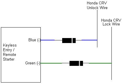
Another quick follow-up question. I'm installing a Python 1400xp keyless entry and remote starter. In that manual, it says that H4 is the "Door Lock Harness", and it says H4/1 is green and (-)Lock (+)Unlock, and the H4/3 is blue and is (+)Lock (-)Unlock. They also included a 450m doorlock module.
Do I need to use the 450m, or can I just connect the blue and green wires from the 1400 to the car's lock and unlock wires?
Thanks!
Posted By: loneranger
Date Posted: February 19, 2009 at 12:57 PM
You can connect direct to the lock/unlock switch wires. However, I always recommend you diode isolate the R/S lock/unlock wires, when it's a flip-flop circuit.
-------------
Ideal - cmon dude, add to topics in a useful manner, not stuff that is obvious.
Story - Phzzzt! Hey, what happened?! ... Isn't it obvious?
Moral - Never dismiss the obvious.
Posted By: cpgoose
Date Posted: February 20, 2009 at 6:31 AM
Cool, thanks loneranger. Since it's been a while that I've used diodes, let me just confirm that I will hook it up correctly:
Posted By: loneranger
Date Posted: February 20, 2009 at 1:20 PM
Flip your diodes around. They are backwards. ------------- Ideal - cmon dude, add to topics in a useful manner, not stuff that is obvious.
Story - Phzzzt! Hey, what happened?! ... Isn't it obvious?
Moral - Never dismiss the obvious.
Posted By: cpgoose
Date Posted: February 20, 2009 at 1:24 PM
Crap...I always get that backwards. So by flipping them around it makes it so that the 1400xp can only send the negative pulse TO the unlock and lock wires, right? It prevents signal going TO the 1400xp?
Posted By: loneranger
Date Posted: February 20, 2009 at 2:56 PM
Your concept is correct. DEI, as well as other designs, uses a flip-flop circuit for the outputs. If the factory switch in the vehicle is inadvertently locking, at the same time the flip-flop circuit is unlocking, the module could be severely damaged; or visa-versa. The diodes prevent the positive voltage from grounding, through the factory lock/unlock switches.
-------------
Ideal - cmon dude, add to topics in a useful manner, not stuff that is obvious.
Story - Phzzzt! Hey, what happened?! ... Isn't it obvious?
Moral - Never dismiss the obvious.
Posted By: howie ll
Date Posted: February 20, 2009 at 3:21 PM
We had loads of iritations with DEI/Clifford early G5 product with those flip flop driven lock outputs, I got to "conditioning" every install! Thanfully they listened to our complaints and made them relay driven last year.
Posted By: loneranger
Date Posted: February 20, 2009 at 3:39 PM
DEI is no longer using a trasistorized circuit, for the lock/unlock outputs on 2-wire models? Which models are you speaking of? I haven't seen any on-board relays yet, much less 5-wire outputs. Maybe they mis-informed you and they are using current-limiting instead, or I could be completely off base. ------------- Ideal - cmon dude, add to topics in a useful manner, not stuff that is obvious.
Story - Phzzzt! Hey, what happened?! ... Isn't it obvious?
Moral - Never dismiss the obvious.
Posted By: howie ll
Date Posted: February 20, 2009 at 4:22 PM
The Euro Cat G5 AKA Concept 650 was based on the Concept 550 with various upgrades to turn it into a UK Cat1*. The siren becomes battery back up, the CPU gets an armoured case which must be bolted/screwed or cable tied home, dual circuit passive immobilisers, all immob and power and ground lines black, mandatory hood, trunk and door contacts. And of course stealth wiring, solder joints etc. We had loads of complaints centred around the lock outputs, high sensitivity to sleep circuits, and the Wiz V2.2 was a nightmare when adding Intellistart. They modded it 18months ago, to the Concept 650 Mk ll with the new silver remotes, effectively an Intelliguard 850 modded as above. Now it has relay driven outputs, a total (comfort close) option and it's step sister Viper 500XV is similar except for two way remote. Just a point for your clarification, the rest of the world outside North America uses amber indicators front and back, thus we don't wire to the lights, we wire to the indicators or hazards. *UK Cat l is recognised everywhere but Australia/NZ. They require 3 cut . The insurers started Cat l, especially for fast and furious type Japapnese imports, without transponders etc. The (irritating) passive immobilisation is thanks to German TUV.
Posted By: loneranger
Date Posted: February 21, 2009 at 3:39 PM
Wow! Thanks for schoolin' me!
-------------
Ideal - cmon dude, add to topics in a useful manner, not stuff that is obvious.
Story - Phzzzt! Hey, what happened?! ... Isn't it obvious?
Moral - Never dismiss the obvious.
Posted By: cpgoose
Date Posted: March 17, 2009 at 8:46 PM
Hey guys...hopefully you're still subscribed to this post...I just had a few questions now that I'm almost done.
1. I'm trying to figure out whether the Python brain in setup for + or - output for the doorlocks. I see that it can do both, but I'm not sure which one it's set to at the moment. Do you know how to check? I never understand how to check with a DMM since I'll get one signal with the 2 wires going one way, and I'll get the opposite (-) signal if I swap them.
2. I found a blue/white wire next to the ECM that I'm assuming in the tach wire. Actually I found 2. One doesn't respond at all to the RPMs, and the other one shoots up very briefly with the RPMs, and then falls back down. I couldn't really get it to hover between 1 and 6v, but I think it's probably the wire.
3. As I've seen in a lot of other posts, the door lock spot refers to the TechTip 1041, but I don't have access. Does that have anything that I'd need to know?
Thanks!~
Posted By: chriswallace187
Date Posted: March 17, 2009 at 9:17 PM
cpgoose wrote:
Hey guys...hopefully you're still subscribed to this post...I just had a few questions now that I'm almost done.
1. I'm trying to figure out whether the Python brain in setup for + or - output for the doorlocks. I see that it can do both, but I'm not sure which one it's set to at the moment. Do you know how to check? I never understand how to check with a DMM since I'll get one signal with the 2 wires going one way, and I'll get the opposite (-) signal if I swap them.
This isn't a programmable option. When "lock" is pressed on the remote the green wire will output a (-) pulse and the blue will output (+). When "unlock" is pressed the opposite will happen. Most cars with positive or negative 3-wire door lock systems can be directly connected to these wires and the (in your case) positive pulse will have no effect since the wires rest at 12V+ through the factory relays/lock controller. cpgoose wrote:
2. I found a blue/white wire next to the ECM that I'm assuming in the tach wire. Actually I found 2. One doesn't respond at all to the RPMs, and the other one shoots up very briefly with the RPMs, and then falls back down. I couldn't really get it to hover between 1 and 6v, but I think it's probably the wire.
You could try "tach-find-by-fire", if you don't mind the name I've just coined for it. Connect the violet/white from the Python temporarily to the suspected tach wire, and attempt to program it to the Python. If the LED never comes on, it won't work. If the LED lights up, it's probably good and you can attempt a remote start to verify that the cranking time is sufficient and not excessive.
cpgoose wrote:
3. As I've seen in a lot of other posts, the door lock spot refers to the TechTip 1041, but I don't have access. Does that have anything that I'd need to know?
Thanks!~
1041 is in the Downloads section of this site. Look at it if you like - it's simply a guide to the different types of lock systems. ------------- C Renner's Auto Electronix
My service is cheap, quick, and good - pick any two
Posted By: howie ll
Date Posted: March 18, 2009 at 4:15 AM
Adding a thought to what Chris said, with those flip flop low current outputs, I found a few years ago to always diode them to avoid silly problems. They wouldn't even work on BMWs or UK Fords with factory KE systems. I noticed on DEI's latest install manuals that they NOW tell you to use diodes as well. Chris, "your find by fire" is a great system, been using the "let's hope it's this one, connect the tach wire to it and see if it programmes" approach for sometime now, then if it works solder and seal off. Trouble is I sometimes forget to solder! (The Danny Crane Syndrome)
Posted By: cpgoose
Date Posted: March 18, 2009 at 1:17 PM
Thanks again guys...I'll try the find-by-fire method :) Three more questions for you if you don't mind.
1. Would you guys happen to know if there is a "hood" wire for the car? This way I don't have to use that dumb hoodpin switch that comes with it.
2. I was going to hook up a siren to the brown wire instead of the car's horn. I can do this without a relay, right?
3. I have what I'm assuming are the "progressive" door locks where the first time I hit unlock it opens the driver's door, and the second time I hit it all the doors unlock. If I want to keep them progressive, can I just not use H1/6 Blue wire and it will act normally (when the car is running remotely)?
Thanks!
Posted By: loneranger
Date Posted: March 18, 2009 at 3:35 PM
- 1. I'm unsure.
- 2. No. The output does not supply enough current.
- 3. The vehicle's K/E does have 'progressive unlock'. I'm not fully understanding what you're asking. Re-phrase your question.
------------- Ideal - cmon dude, add to topics in a useful manner, not stuff that is obvious.
Story - Phzzzt! Hey, what happened?! ... Isn't it obvious?
Moral - Never dismiss the obvious.
Posted By: cpgoose
Date Posted: March 18, 2009 at 3:43 PM
2. The manual only says I need a relay if I need to convert the signal from (-) to (+). I was assuming if I didn't need a relay for the horn, then I wouldn't need one for the piezo, but I guess that's wrong thinking?
3. Basically if I hook up the Python KE/RS and I want to maintain the vehicle's progression unlock, is it ok to just tape off the H1/6 BLUE wire?
Thanks for the reply!
Posted By: howie ll
Date Posted: March 18, 2009 at 4:13 PM
You don't need a relay for the Siren, you might well for the horn unless the horn lead at the steering column has a relay after. First does horn work without ignition if not forget the rest. Find horn lead at steering column, first see if it's pos or neg, if pos lead to 85 on relay, 12v+ to 86 and 87, 30 to horn wire. If neg, place your meter in DC 10amp test mode, red to horn wire, black to ground see how much current is drawn when it sounds the horn. If 100milliamps or less you're OK to wire directly. To maintain progressive lock, use the alarm's green to lock and blue via a relay to DRIVER's unlock motor wire as follows blue to 85, 7amp fused 12v+ to 86 and 87, car side of driver's unlock wire to 87a and motor side to 30. Take your secondary unlock wire to 85, 15amp fused 12v+ to 86 and 87 car side of passenger unlock wire to 87a and motor side to 30. That's it.
Posted By: chriswallace187
Date Posted: March 18, 2009 at 4:27 PM
1. Audiovox states hood trigger is light blue, in harness in driver kick panel.
2. The horn switch wire is low current and activates a factory relay - that's why you don't need to add your own to control it with the Python's low current horn output. A siren would draw more current than the horn output is capable of supplying; therefore a relay is necessary.
3. With the car running remotely, the factory keyless entry won't work at all (Honda factory keyless entry stops working when the ignition is on). Therefore you'll need to use the Python's remote for keyless entry. If you want it to unlock progressively, you'll need to utilize the H1/6 blue "2nd unlock" output as well as a relay, and make the following wiring changes:
Blue " (-)unlock, (+) lock" will go to pin 85 of the relay.
Pins 86, 87 will go to constant fused 12V+.
Pins 87a and 30 will go to the driver's door unlock motor lead, which should be gray with silver dots in the harness going into the driver's door. To verify that you have the correct wire, cut the suspected wire in half and operate the power lock switch in both directions. The driver's door should not operate but all the others should.
30 from the relay will go towards the actuator in the door, 87a will go away from it.
Last - the H1/6 "2nd unlock" output will go to the (-) unlock switch wire on the car.
-------------
C Renner's Auto Electronix
My service is cheap, quick, and good - pick any two
Posted By: cpgoose
Date Posted: March 18, 2009 at 9:15 PM
Thanks for the replies guys...you're really helping me out a lot.
I believe I've reached the testing/aggravation stage :)
I have all the wires temporarily hooked up, and nothing happens when I hit the Python remote (in terms of the lock/unlock button or the remote starter. If I hold the lock button, the panic kicks in, so at least I know it's getting the signal. If I disconnect the RS ribbon connection, then the Python "clicks" when I hit the lock/unlock on the Python remote, but the doors don't lock/unlock.
I'm using the blue wire and grey wire for the door locks. They seem to respond with the multimeter and when I use the switch on the door. But when I hook them up to the Python, nothing happens.
Can't I supply ground to the wires that I'm using for the lock / unlock to make sure it's the right wires? Now that I think about it, maybe I can't. Ugh, it's too late to be doing this. I'm probably missing something totally stupid. Oh, and I'm using the Fortin electronics bypass by the way.
Posted By: loneranger
Date Posted: March 19, 2009 at 5:49 AM
cpgoose wrote:
They seem to respond with the multimeter and when I use the switch on the door.
What exactly do you mean by "respond"? cpgoose wrote:
Can't I supply ground to the wires that I'm using for the lock / unlock to make sure it's the right wires?
Yes. However, I highly recommend you fuse the GROUND at ~1A or less. ------------- Ideal - cmon dude, add to topics in a useful manner, not stuff that is obvious.
Story - Phzzzt! Hey, what happened?! ... Isn't it obvious?
Moral - Never dismiss the obvious.
Posted By: cpgoose
Date Posted: March 19, 2009 at 6:51 AM
loneranger wrote:
cpgoose wrote:
They seem to respond with the multimeter and when I use the switch on the door.
What exactly do you mean by "respond"?
I mean that as I'm probing the wires and I hit the lock/unlock button on the door, the meter jumps all the way up and then falls back down. I can't really tell how many volts it shows because it happens so fast. That's why I'm assuming I have the right wires.
cpgoose wrote:
Can't I supply ground to the wires that I'm using for the lock / unlock to make sure it's the right wires?
Yes. However, I highly recommend you fuse the GROUND at ~1A or less.
I literally take a spare wire and touch one end to the car's chassis and touch the other end to the wire that I'm testing, but unfortunately it doesn't do anything. Is this because it uses a transponder?
Posted By: cpgoose
Date Posted: March 19, 2009 at 3:33 PM
I've also skipped a bunch of wires that I don't want to use. I'm assuming that's ok, and it's not causing the system to not respond.
For example, I skipped:
1. H1/1 (RED / White) Channel 2
2. H1/3 (Brown) Horn honk
3. H1/7 (Blue) Second unlock
4. H1/9 (BLACK/ White) Domelight Supervision
5. H1/10 (WHITE/ blue) Remote start activation input
6. H1/11 (white) Selectable Light Flash Output
7. Relay satellite wire: RED / white (12v input)
8. H2/1 (Violet/black) Channel 4 output
9. H2/2 (GREEN / WHITE) factory rearm output
10. H2/3 (Gray/Black) Diesel wait-to-start bulb input
11. H2/4 (Light GREEN/ Black) Factory alarm Disarm
12. H3/1 (BLACK/ White) Neutral Safety Switch Input (I grounded this)
13. H3/4 (Gray) Hood pinswitch input (I taped this off)
14. H3/5 (Blue/White) Status/Defogger output
I also didn't plug in the LED or VALET SWITCH.
Is it ok to do this, or do some of those wires have to be used regardless?
Posted By: howie ll
Date Posted: March 19, 2009 at 6:33 PM
Here's where you take it to a reputable install shop where you pay to have it ripped out and re-installed properly. Of course it uses a transponder, just remove the steering column cowling and look at that nice antenna around the ignition switch. By the way your testing method two posts ago is so irresponsible if someone working with were doing that I'd have fired them immediately. I call it testing by fire.
Posted By: cpgoose
Date Posted: March 19, 2009 at 7:30 PM
Yea, thanks...I'll never take it to someone. Talk about ripoff. I've figured out the last 4, and I'll get this one too.
|