93 ford f150, crimestopper cs
Printed From: the12volt.com
Forum Name: Car Security and Convenience
Forum Discription: Car Alarms, Keyless Entries, Remote Starters, Immobilizer Bypasses, Sensors, Door Locks, Window Modules, Heated Mirrors, Heated Seats, etc.
URL: https://www.the12volt.com/installbay/forum_posts.asp?tid=110722
Printed Date: January 29, 2026 at 10:25 PM
Topic: 93 ford f150, crimestopper cs
Posted By: usman13
Subject: 93 ford f150, crimestopper cs
Date Posted: January 16, 2009 at 7:06 PM
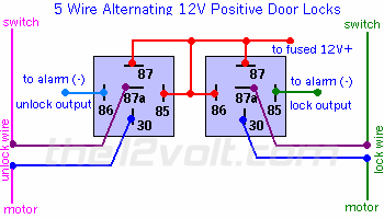
i'm installing a crimestopper cs 2014 dp II in a 93 ford f150. I know it has reverse polarity locks and i tried to hook up the wires according to the relay diagram ( 5 wire ). No luck ...the crimestopper has negative lock/unlock any suggestions.. | 5 Wire Alternating 12 Volts Positive Door Locks | Like the configuration above, the switch, when moved in either direction, applies both power and ground directly to motor legs without the use of any relays. Except, at the switch in this case, both motor legs rest at ground . Therefore it is only necessary to change the polarity of one motor leg to lock or unlock the vehicle.
 |
Replies:
Posted By: monty_77
Date Posted: January 16, 2009 at 7:47 PM
if you did wire it like above are you sure you have the motor and the switch side right. if not you may want to try to switch 87a and 30 around on both and try it again.
This diagram is set up for negative outputs.
Posted By: 91stt
Date Posted: January 16, 2009 at 8:17 PM
What do you mean "no luck?" Are the relays tripping? Are you blowing fuses? Does the factory lock switch still operate the locks? It is probably wired incorrectly.
Posted By: usman13
Date Posted: January 16, 2009 at 8:31 PM
relays click .. factory locks still work from either door ...but not from the remote..the lcd changes to lock and unlock ....??? I'm going to double check the lock and switch position on the relay s tomorrow and update thanks all
Posted By: advanced
Date Posted: January 17, 2009 at 9:41 AM
LCD changes don't mean the door locks are working. If the relays click when you hit lock & unlock on your transmitter, and you are not blowing fuses, and the door lock switches still work, then it sounds like you don't have 12V+ at both pins 87 of your relays. Where are you getting your 12V+ source? ------------- Good Enough Isn't!
Posted By: usman13
Date Posted: January 17, 2009 at 4:40 PM
ok tested both 87 pins they are getting 12 v constant checked the door lock wires according to instructions push and hold the button, the side of the wire when cut is getting 12 v is the switch side the other the motor side. The switch side goes to 87a and the motor side to 30. repeat for both lock / unlock https://www.bulldogsecurity.com/pdf/typec.htm
Posted By: 91stt
Date Posted: January 17, 2009 at 10:01 PM
check to make sure terminal 30 goes to +12V they are suppose to when the remote is activated for both relays.
Posted By: usman13
Date Posted: January 18, 2009 at 4:55 PM
it's only showing 3-4 volts when the remote is pushed ...relays are only making a buzzing sound..
Posted By: 91stt
Date Posted: January 18, 2009 at 8:37 PM
May sound like an odd question but what kind of relays did you get? Try removing the neg. lock/unlock wires and apply ground to the relays one at a time to see if the locks operate. It almost sounds like you are using 24V relays.
Posted By: usman13
Date Posted: January 19, 2009 at 9:19 AM
i'm installing a crimestopper cs 2014 dp II in a 93 ford f150. The truck will not remote start. I unhooked the hood pin switch thinking it was the problem no luck. The strange thing is I have idle down mode (truck running hit remote start button and take keys out truck stays running ) that works perfect ??
Constant 12V+ Yellow Ignition Switch Harness
Starter RED / Light Blue Ignition Switch Harness
Ignition RED / Light Green Ignition Switch Harness
Accessory Gray / YELLOW Ignition Switch Harness
Tach Tan / YELLOW Coil
Posted By: usman13
Date Posted: January 19, 2009 at 11:00 AM
I tried posting this as a new topic but got moved ?
Posted By: usman13
Date Posted: January 19, 2009 at 11:20 AM
the relay is 961A-1C-12DM NO:40A/NC:30A 12VDC
Posted By: 91stt
Date Posted: January 19, 2009 at 1:33 PM
That seems to be a regular 12V relay. If it is wired according to the diagram, it should work. Try activating the relay with a jumper wire to ground as I mentioned earlier to see if it works. Are you using a relay socket or just quick disconnects to connect the relay for keyless entry? Where are you sourcing your 12 volts from? Have you check all the connection to make sure they are solid and not loose?
Posted By: usman13
Date Posted: January 19, 2009 at 2:05 PM
ok tried that just buzzing sound. I'm getting my 12 v power supply right off the main power going into my alarm which is hooked up to the battery. I noticed something that the wires that are supposed to be hooked to my (-) input on the relays are testing 12v positive ???
Posted By: usman13
Date Posted: January 19, 2009 at 2:06 PM
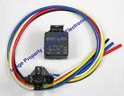
by the way i'm using a relay socket
Posted By: 91stt
Date Posted: January 19, 2009 at 3:35 PM
It is ok to read 12volts on the neg side of the coil when it is not energized. Take a look at the diagram that is stamped on the relay. Is there a diode pictured across the coil? If there is, which direction is it facing, is the stripe towards terminal 85 or 86? If there is a diode and the stripe is towards 86 than this may be your problem. If this is the case you need to swap the wires between 85 & 86 on both relays.
Posted By: usman13
Date Posted: January 19, 2009 at 4:31 PM
nope no diode 
Posted By: 91stt
Date Posted: January 19, 2009 at 4:55 PM
Pull the relays and measure the resistance across the coil both ways and post up your results.
Meter (+) to 85, (-) to 86
and
Meter(+) to 86, (-) to 85
Posted By: ckeeler
Date Posted: January 19, 2009 at 6:39 PM
do your relays have 2 terminals marked 87? or one marked 87, and one marked 87a? they should be 87 and 87a.
Posted By: usman13
Date Posted: January 19, 2009 at 9:27 PM
87 and 87a
Posted By: usman13
Date Posted: January 24, 2009 at 10:33 AM
i'm getting 85.6 - 86.2 on both relays both ways
Posted By: 91stt
Date Posted: January 24, 2009 at 8:21 PM
The resistance is good.
The only think I can think of is that the output from the brain is poor.
Have you tried energizing the relays with a jumper to ground yet?
Posted By: loneranger
Date Posted: January 24, 2009 at 8:33 PM
91stt] wrote:
s there a diode pictured across the coil? If there is, which direction is it facing, is the stripe towards terminal 85 or 86? If there is a diode and the stripe is towards 86 than this may be your problem. If this is the case you need to swap the wires between 85 & 86 on both relays.
If that is the case, both outputs on the module are now damaged. Once again, look on the back of the relay socket, not the relay, and see if there is a diode across the #85 and #86 wires. ------------- Ideal - cmon dude, add to topics in a useful manner, not stuff that is obvious.
Story - Phzzzt! Hey, what happened?! ... Isn't it obvious?
Moral - Never dismiss the obvious.
Posted By: usman13
Date Posted: January 24, 2009 at 10:18 PM
thanks for the reply ...yes double checked ho diodes anywhere. I return the brain box and try again
|

