dei 712t with 5 wire actuators
Printed From: the12volt.com
Forum Name: Car Security and Convenience
Forum Discription: Car Alarms, Keyless Entries, Remote Starters, Immobilizer Bypasses, Sensors, Door Locks, Window Modules, Heated Mirrors, Heated Seats, etc.
URL: https://www.the12volt.com/installbay/forum_posts.asp?tid=110730
Printed Date: May 09, 2026 at 7:06 PM
Topic: dei 712t with 5 wire actuators
Posted By: jamin76
Subject: dei 712t with 5 wire actuators
Date Posted: January 17, 2009 at 12:25 AM
Okay, i am installing a Spal power door lock kit and the actuators are 5-wire. I am also going to install a DEI 712t Keyless entry system and i have no idea how to connect the two units so that they function properly. Any help would be greatly appreciated!
Replies:
Posted By: howie ll
Date Posted: January 17, 2009 at 1:44 AM
The spal kit should come with a control relay, then low current neg lock outputs from the 712t would be sufficient, if no relay you wouldn't need 5 wire actuators because you won't be able to control from outside by turning a key in front door locks. If the 712t has a 2 wire lock output you will need two relays or a 450t relay package from DEI, if not i.e. 6 wire poutput from 712t you won't need relays, just follow the instructions from the 712t.
Posted By: jamin76
Date Posted: January 17, 2009 at 1:52 AM
The Spal kit has a control relay but there are not any inputs on it for a keyless entry system. The 712t has a built in relay on it. If i were to cut the purple, brown and green wires from the actuators would the 712t act as a central lock control with manual lock operation? If i cut them, how then would i wire them to the 712t, would i need additional relays?
Posted By: jamin76
Date Posted: January 17, 2009 at 2:53 AM
I think this is what i am looking for but i am not positive! 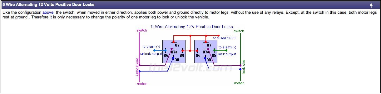
Posted By: howie ll
Date Posted: January 17, 2009 at 11:11 AM
You really are going around the houses, if there are 5 wires going to each actuator 2 are motor wires, probably either green and blue for far east sourced or red and blue for European sourced. Of the other three wires, 1 will go to ground probably black, set up your motors, wire them up then join the black in turn to either of the two remaining wires near the relay control unit. this will actuate lock/unlock. Once you work out which is which connect your green lock and your blue unlock wires from the 712t with the 712t locks set up as neg switching, ie purple and PURPLE / black to ground, WHITE/ black and BROWN / black unused. As a tip only connect the 5 wires to your driver's actuator, as positioning problems mess around with the internal switch in the atuator. You will save yourself a lot of time and effort taking that piece of advice. There no relays required. What is it with DIYers and relays? You will probably find those two switching wires in the loom near the control relay, I recognise it. It's far east sourced if black and Euro sourced if blue. Now go ahead and don't drive me mad.
Posted By: jamin76
Date Posted: January 17, 2009 at 5:03 PM
I was showing the picture of the relays to represent the built in relays on the 712t and not in addition to it. I apologize for the confusion, as i am new to this side of electronics. Let me try and explain more clearly the entire set up so that i make sure that i understand you correctly. The Spal power lock kit consists of 2 5 wire actuators with red, blue, purple, brown and black wires and it has a control unit So if i understand you correctly i will install the Spal kit with the supplied control relay, then splice the green lock and blue unlock wires from the 712t to the blue and red wires on the Spal harness near the control relay and ground the two #87 N.O. inputs. Then i will only hook up the red and blue wires on the passenger actuator to the control relay. Sorry to be a bother but i just want to make sure that i understand you correctly and i really appreciate you taking the time to explain this to me!
Posted By: howie ll
Date Posted: January 18, 2009 at 4:40 AM
The brown and purple are the leads that you are looking for they are the neg lock/unlock switching wires just connect to blue/black and GREEN/ black from the 712 set to neg output. It seems that you have the Italian made kit, there should be 2 tails at the relay end, with brown and purple, if not join at the relay. The blue and reds going to the motors are MOTOR WIRES, don't join your 712 to them and STOP thinking about relays.
Posted By: jamin76
Date Posted: January 20, 2009 at 1:46 AM
Thanks for helping me out, i really appreciate it!
|