electronic turn signal substitute?
Printed From: the12volt.com
Forum Name: Car Security and Convenience
Forum Discription: Car Alarms, Keyless Entries, Remote Starters, Immobilizer Bypasses, Sensors, Door Locks, Window Modules, Heated Mirrors, Heated Seats, etc.
URL: https://www.the12volt.com/installbay/forum_posts.asp?tid=111590
Printed Date: May 06, 2026 at 4:18 AM
Topic: electronic turn signal substitute?
Posted By: angelars
Subject: electronic turn signal substitute?
Date Posted: February 14, 2009 at 11:21 AM
Can you guys refresh my memory? Its been a while since I've bought anything like this. I'm looking for something that would be an electronic version of a turn signal relay. It needs to be adjustable so that I can set it to any time interval between 1 and 30 seconds. Like a turn signal it would be triggered, turn on, turn off, wait for how ever long you set it for, and then repeat the process. I'm sure DEI or PAC makes something like this. Can you direct me to part numbers? Thanks!
Replies:
Posted By: Chris Luongo
Date Posted: February 14, 2009 at 11:51 AM
Look around for the people who sell sequential turn signal kits for cars. Try sequentialturnsignals.com, but there are other sites too. They might be able to point you in the right direction.
Also, not to sure if they'll do what you want, but some part numbers to look at are: DEI 528T, and PAC TR-7.
Posted By: angelars
Date Posted: February 14, 2009 at 12:08 PM
Chris Luongo wrote:
some part numbers to look at are: DEI 528T, and PAC TR-7.
Thanks Chris! Can you verify that the DEI 528T will pulse on/off repeatedly? It needs to go on, off, on, off...ect at a pre-set interval. Thanks.
Posted By: KPierson
Date Posted: February 14, 2009 at 1:19 PM
What are you putting this all in? Whatever it is it sounds like an interesting project.
-------------
Kevin Pierson
Posted By: angelars
Date Posted: February 14, 2009 at 1:26 PM
I am working on developing a system that vibrates the drivers seat when the radar detector goes off. Everything else is finished being developed, I just need a less mechanical way (than a relay and turn signal flasher) of pulsing the signal. I have several other projects in development too.
Posted By: KPierson
Date Posted: February 14, 2009 at 1:40 PM
What kind of current will the vibrator pull?
-------------
Kevin Pierson
Posted By: angelars
Date Posted: February 14, 2009 at 1:57 PM
Very little. Typically less than 2 amps, but final testing won't be until 4-6 weeks as I haven't decided on what to use for the 'pulsing' of the power.
Posted By: KPierson
Date Posted: February 14, 2009 at 4:27 PM
I have some circuit boards here that have two "single turn" adjustment pots and onboard 2A relays. The boards are about 2" x 2". It wouldn't take much code to turn the pots in to ON and OFF time controllers and use the onboard relay to output 12vdc. What kind of output do you have from the radar detector?
-------------
Kevin Pierson
Posted By: angelars
Date Posted: February 14, 2009 at 5:44 PM
It's a negative trigger, but we could also tap off of the LED if needed.
Posted By: howie ll
Date Posted: February 15, 2009 at 10:30 AM
Do they sell Velleman kits in the US? Part no 100 I think will give you trigger on/off repeated. Costs about $8 here.
Posted By: howie ll
Date Posted: February 15, 2009 at 11:02 AM
Here we are,Velleman do three kits, K8015, MK111 and VM141 all with adjustable start, pause, restart functions, all available in North America, I think they would be more suited than a 528t. I'm sure sometime I've built and used an MK111 for this purpose.
Posted By: angelars
Date Posted: February 15, 2009 at 12:00 PM
Wow THANKS howie ll, those all look interesting! Appreciate the information 
Posted By: ckeeler
Date Posted: February 16, 2009 at 12:35 PM
i also have a simple circuit design you could use if interested. it uses 2 NE555U IC's and two adjustable pots to control the timing of the pulses and the duration of each pulse.
Posted By: angelars
Date Posted: February 16, 2009 at 12:57 PM
That would be great Ckeeler! Please PM us or post the schematic 
Posted By: ckeeler
Date Posted: February 16, 2009 at 7:10 PM
C1 and C2 are used in conjuction with the adjustable resistors to control U1 and U2. U1 controls how often the pulses happen and U2 controls how long each pulse is. with this setup you can run up to a 20amp load. 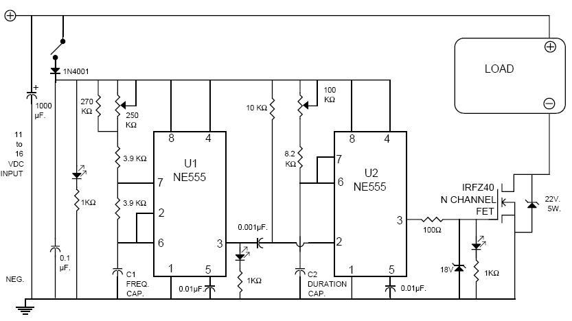
Posted By: angelars
Date Posted: February 16, 2009 at 7:42 PM
THANKS ckeeler. Appreciate the schematic :)
|