keyless entry negative trigger issue
Printed From: the12volt.com
Forum Name: Car Security and Convenience
Forum Discription: Car Alarms, Keyless Entries, Remote Starters, Immobilizer Bypasses, Sensors, Door Locks, Window Modules, Heated Mirrors, Heated Seats, etc.
URL: https://www.the12volt.com/installbay/forum_posts.asp?tid=111940
Printed Date: March 26, 2026 at 6:08 PM
Topic: keyless entry negative trigger issue
Posted By: burn350219999
Subject: keyless entry negative trigger issue
Date Posted: February 25, 2009 at 11:02 PM
I've got an Audivox 996a with a faulty unlock wire. The unit has two wires, one red that pulses a ground on lock and +12v on unlock, the other green which pulses +12v on lock and ground on unlock. The green wire is the one that isn't working. Rather than replace the brain is there a way to use the one red wire to lock and unlock the doors? I've found that I can use a relay to reverse the +12v pulse on unlock to a ground but when I split the red wire into two (one directly to the door lock wire, and the other to the relay and then to the door unlock wire) it seems to confuse the hole system. Is there a configuration I can use to isolate each pulse and if so how would I wire that up?
Replies:
Posted By: 91stt
Date Posted: February 26, 2009 at 12:15 AM
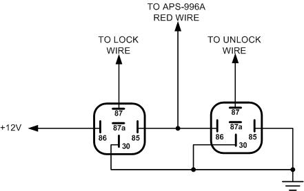
Using two relays should work
Posted By: KPierson
Date Posted: February 26, 2009 at 6:39 AM
It may be possible to repair the alarm. Quite a few alarms use one (or two) darlington transistor chip(s) for all the (-) outputs. This is typically a through hole mounted chip that is readily available (made by Toshiba). I haven't look inside an Audiovox alarm lately though, but it may be worth opening it up and taking a look. Are both the (-) and (+) output bad? If that is the case, it may also just be a burnt trace on the board, something you can fix by soldering in a jumper. ------------- Kevin Pierson
Posted By: Mike M2
Date Posted: February 26, 2009 at 7:01 AM
You will need to doide isolate those relays between the red wire and the relay itself as they will hold a rest current...
-------------
Mike M2
Tech Manager
CS Dealer Services
Posted By: 91stt
Date Posted: February 26, 2009 at 10:34 AM
Mike, you are absolutely right. Now that I think of it, diode isolation may not be enough. Back to the drawing board for now.
KP, I thought about mentioning the option to replace the transistors but was not sure how comfortable the OP would be with that.
Posted By: KPierson
Date Posted: February 26, 2009 at 12:37 PM
How about something like this: 
It uses three 200mA transistors that are easy to find. You may have to play around with the resistors a bit but they should technically work (capable of ~500mA output when transistors can only dissipate 200mA) The top PNP transistor will "trigger" on the (-) pulse while the bottom transistor will ignore the (-) pulse. The top transistor will output 12vdc to the second transistor shown. The second transistor (NPN) will trigger and output a totally isolated (-) signal. The bottom NPN transistor will trigger on a (+) pulse while the top transistor ignores the (+) pulse. The NPN transistor outputs a (-) signal so it can direct drive a relay. You will need to protect the transitors by placing diodes across the coils of any relays you drive. If, for some reason, you need to drive more then one relay off of each output you most likely will have to drop the resistor values down (to 470 or so). While technically you will be over driving the transistors current capacity they should be fine due to the fact they are only on for ~0.8 seconds at a time. I've never tried this, but I do think it will work. ------------- Kevin Pierson
Posted By: moonliter
Date Posted: February 26, 2009 at 1:24 PM
Since the unlock output green (-) is faulty, can't you just use the 2nd unlock output RED / black (-) instead ? All you have to do is just press the unlock button twice to unlock.
Posted By: Chris Luongo
Date Posted: February 26, 2009 at 4:01 PM
Two options:
1. Use the RED / black second unlock. You'll have to hit Unlock twice on your transmitter, though.
Also, I don't remember the default on the APS996, but in the programming menu, the "second unlock output" or whatever they call it must be set to "on."
2. Use your BLACK/ blue "pulse before start" output to unlock the doors.
That wire makes a pulse with unlock, and also makes a pulse when you activate the remote starter.
Then you'll also want to connect the BLACK/ green "pulse after start" to the car's lock wire.
Now, the car will briefly unlock every time you remote start it, but then it'll lock right back up.
Posted By: burn350219999
Date Posted: February 26, 2009 at 11:25 PM
Thanks for all the different suggestions. I tried the second unlock wire, that one turned out to be bad as well. Oddly enough although the green wire wouldn't produce a ground pulse it would still produce a +12V pulse so I ended up using two relays to reverse polarity and hooked up the wires backwards.
|