i have a scytek 5000rs alarm, i want to add the antigrind/starter defeat this is the diagram as shown in the manual
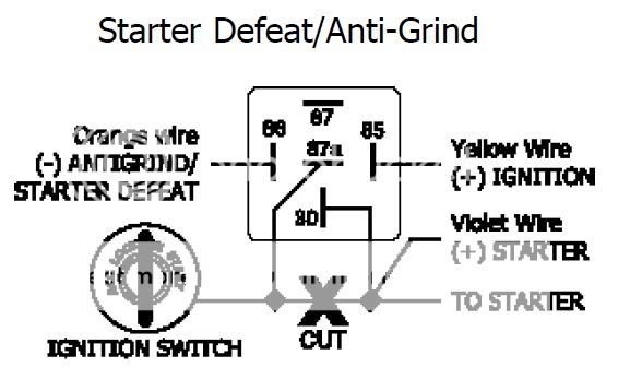
so the orange wire is from the brain
87a is the starter wire from the ignition switch
these are the next part i need verification from..
for pin 30 i know the other end of the starter cable going to the starter motor goes there, but the other one listed here is a violet wire. i believe they are talking about the starter output wire from the brain? so i just put them both on pin 30? this one i believe im correct based on a few searches here verifying that.
pin 85 is the one that is confusing me. its for the yellow ignition wire from the brain i believe. however on the brain i have 2
- the one from the starter harness
- the one from the main harness
the one from the starter harness is an output
the main harness one is listed as ignition INPUT (+) (must be connected) its described in the manual as: +12v ign input. wire must connect to a main ignition wire at the ignition harness. this wire must show +12v when ignition is on and while cranking the starter. the voltage must not drop when car is starting.
so i dont know there. if i connect the ign yellow wire from the starter harness on the brain, it doesnt seem logical. or since both of those wires need to connect to the ign wire at the ign switch, do i just run a T-tap from there to pin 85?
Basically, terminal #85 needs only a low current IGN source. The wire only needs to be ~22ga. You can use either the R/S IGN output wire or the factory IGN wire as a source, as they are both electrically the same when the installation is completed. I would just solder a ~22ga wire at the same junction as the connection for the R/S IGN ouput wire to the factory IGN wire. Then connect the ~22ga wire to terminal #85.
Regarding the starter wires, trying to stuff both the R/S STR and the factory STR wire in to a connector for terminal #30 can be difficult. I would suggest putting your connector on the R/S STR wire and soldering your factory STR wire to the R/S STR wire.
-------------
Ideal - cmon dude, add to topics in a useful manner, not stuff that is obvious.
Story - Phzzzt! Hey, what happened?! ... Isn't it obvious?
Moral - Never dismiss the obvious.
thanks for clarifying loneranger.
loneranger, i forget to mention, my vehicle actually has 2 IGN wires.
all the other wires I connected already thanks to your help, for the setup above, do I just focus mainly on the IGN 1 wire?