indicator flash on unlock solution
Printed From: the12volt.com
Forum Name: Car Security and Convenience
Forum Discription: Car Alarms, Keyless Entries, Remote Starters, Immobilizer Bypasses, Sensors, Door Locks, Window Modules, Heated Mirrors, Heated Seats, etc.
URL: https://www.the12volt.com/installbay/forum_posts.asp?tid=117502
Printed Date: May 03, 2026 at 8:58 AM
Topic: indicator flash on unlock solution
Posted By: wigs1l
Subject: indicator flash on unlock solution
Date Posted: November 06, 2009 at 12:29 AM
Hi there, new to the site.
I'm from the uk and have a Ford Mondeo 2003.
I'm looking for a way to make my indicators flash once when i unlock via remote, which they don't do currently.
I know from a friend who has a 2004 model that his does, and from other forums, this feature was added on later models, but after the build date of my car.
I would be looking to take the pulse from the alarm module to the door lock actuator or the courtesy lights circuit, or anywhere esle you can think of!
Can anyone please advise how to do this, via a relay, or any other suggestions??
Replies:
Posted By: howie ll
Date Posted: November 06, 2009 at 1:16 AM
Look above the throttle pedal there's a black plastic box with multiple plugs of different colours. Called the GEM box. The simplest way is to find the unlock motor wire which is probably white or WHITE/ black. Open the driver's door then throw the latch on the door lock (back end of door). Use the locking push in the inner handle to make sure the locks work, i.e. lock and unlock and you are ready to go. Take a DMM* and set it to 20VDC. Place the black probe to a good ground (earth)and the red side to to one of those wires. when you push the handle or use the remote fob to unlock, one of those wires will read 12v+. That's the one you want. Also on that box are a plain blue and a blue/red wire adjacent to each other. These are your indicator wires. Again use a DMM the same way to test. Once you've ascertained this, connect the unlock motor wire to relay 86, earth to 85, constant 12v+ (probably a ORANGE / colour) adjacent to the indicators, again test) to 30 and from 87 split via 2 x 2N5404 diodes, bands away from relay to your blue and blue red indicator wires. You can make this more sophisticated with an ignition control relay such that it only works when ignition is off; take a feed from an ignition circuit (should be GREEN/ YELLOW in the ignition loom) to a second relay 86, ground to 85, then take the 87 wire from the first relay, bring it to 30 and out from 87a. * You can do all this with a test light but it's not advisable because I know what I'm doing here, I wrote the play book for Clifford on this car and you might feed 12V to the wrong wire and blow the box. You could also conceivably do this without the first relay, just diodes but it's inadvisable long term.
Posted By: wigs1l
Date Posted: November 06, 2009 at 1:30 AM
Excellent. You've explained very clearly, thanks for the quick reply.
Where exactly can i take the earth from?
Posted By: wigs1l
Date Posted: November 06, 2009 at 2:09 AM
and from 87 split via 2 x 2N5404 diodes, bands away from relay to your blue and blue red indicator wires
could you expand a little on this for me please?
Sorry for being a pain, but its not something i'm familiar with, so please excuse my ignorance!
Posted By: howie ll
Date Posted: November 06, 2009 at 8:06 AM
Take down the lower dash and the right hand kick panel, there should be cables grounded via bolts. Any of them. As for the diodes, I meant 1N5404. I've been duly told off. Take 1 wire from 87, make a "Y" joint and place each diode in line, then out to each indicator wire.
Posted By: wigs1l
Date Posted: November 06, 2009 at 10:30 AM
Thank you sir, very helpful. Will let you know how i get on!
Posted By: wigs1l
Date Posted: November 08, 2009 at 6:48 AM
HI there...again!
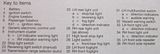
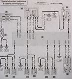
I have a Haynes manual for my car with wiring diagrams of the indicators, please see HERE, and have a couple of questions as I have been studying the diagrams and need to know if I'm on the right track! (Note that the GEM is box 8 on the diagram)
I have built the relay but had to go slightly different, I have made it with 4 wires coming from 87, I haven't installed yet.
Can I have pin 87 of relay split into 4 with two "Y" joints with 4 diodes,to tap into the 4 indicator wires (2 blue+2 blue/red) coming from the GEM??
OR
Can I have pin 87 of relay split into 2 with your "Y" joint and diodes, to tap into the 2 BLACK/ green wires coming from box 31 on the diagram going into the GEM??
OR
Can I just leave pin 87 as one wire to tap into the single BLACK/ orange wire coming from box 32, which is the hazard switch wire going into the GEM?
The reason I'm asking is because I want to cut down on the amount of wires I need to tap into, so which of the above situations would work best for me?
Thanks for taking the time to read through, I understand if you're getting slightly bored with this topic now, I do ramble on a bit!
Posted By: i am an idiot
Date Posted: November 08, 2009 at 7:49 AM
We do not have permission to view the link you posted.
Posted By: wigs1l
Date Posted: November 08, 2009 at 9:17 AM
link above didn't work, so try these
Posted By: howie ll
Date Posted: November 08, 2009 at 10:25 AM
Does that black /orange flash the indicators for as long as it's grounded? If so just do the following take the lock wire, either yellow, white black or yellow/black from the GEM box, one is unlock, one is deadlock, the third will be unlock. Take your feed to relay 86, ground 30 and 85, feed 87 to the BLACK/ orange, job done. You wont need diodes.
Posted By: wigs1l
Date Posted: November 08, 2009 at 10:48 AM
Ok will give it a go
Posted By: wigs1l
Date Posted: November 13, 2009 at 6:14 AM
Hi there, just an update. Found the remote unlock pulse, it was the WHITE/ black.
So, connected pin 86 to WHITE/ black and joined pins 85+30 and grounded them. Connected 87 to BLACK/ orange, which is the feed to the GEM from hazard switch.
Can hear an audible click from the relay when I unlock, which shows we're on the right track, but indicators do not flash. GRRRRRRRRR!
So, do I try to go back and split 87 into four and connect up to the various blue+blue/red? (its starting to annoy me now!)
When I lock the car, no indicator. When I double lock, they all flash twice. I realise this is all done insdie the GEM, but there has to be a simple way for me now, as I've done most of it, just getting the output from 87 to go where I need it to!
Any more suggestions??
I was thinking of splitting 87 into two, and connecting to the 2 BLACK/ green coming from box 31 on the diagram I posted earlier.
Do you think this would work?
Or, maybe keeping 30+85 seperate, put 12v to 30 and keep 87 going to the BLACK/ orange?
Posted By: howie ll
Date Posted: November 13, 2009 at 10:13 AM
your first line connect the white black to 86, ground (earth) to 85, constant 12volts,fused at 20amps to 30, and 87 via the 2 x 1N5404 diodes band out to the blue and blue/red indicator leads on the GEM box. Job done. Now you've tested it, add the following. disconect the diodes and take 87 to 30 of your second relay, ignition to 86 and ground to 85, output from 87a to your diodes and the indicator lights. This mod wil stop the indicators flashing if you lock the car on the move. The way you wired it up you're very lucky you didn't burn out your locking system. I told you this on my first post so please listen. this would be a 5 minute job for me. In fact with 5 relays i could make this flash twice for lock and once for unlock!
Posted By: wigs1l
Date Posted: November 13, 2009 at 10:48 AM
Ok. Please don't lose patience! I'm trying to learn! As I say, I'm new to this, which is why your advice is valuable to me.
When you say I'm lucky I didn't burn out the locking system, I just followed your instructions from your last post on the first page!
I need all indicators to flash on unlock and you can see in the diagram, there are 2Xblue and 2Xblue/red wires comimng from the GEM to go to boxes 25+26, 33+34 and 35+36, which are each of the indicators, front, back, left and right.
Do I need 4 diodes to cover each of these?
And in your last post, if I use the output from 87a, does 87 stay unused on the second relay?
Again, I 'm sorry for being useless at this!
Posted By: howie ll
Date Posted: November 13, 2009 at 2:49 PM
87a is not used on the first relay, use 87. One the second relay use 87a not 87. This means that turning on the ignition wil prevent the indicators coming on if you lock the car whilst driving. I will check with autodata on those blue wires at the GEM box, there should only be 2; blue and blue/red. If in doubt, test.
Posted By: howie ll
Date Posted: November 13, 2009 at 3:02 PM
Autodata says you're right, but I've only ever noticed two wires! If you find 4, test them, also I just remembered, if you probe with a test light with one end to earth, one wire, I THINK GREEN / WHITE will flash the indicators. Try it and let me know, it will be a much simpler circuit.
|

