need ideas, approach lighting
Printed From: the12volt.com
Forum Name: Car Security and Convenience
Forum Discription: Car Alarms, Keyless Entries, Remote Starters, Immobilizer Bypasses, Sensors, Door Locks, Window Modules, Heated Mirrors, Heated Seats, etc.
URL: https://www.the12volt.com/installbay/forum_posts.asp?tid=117660
Printed Date: March 24, 2026 at 4:23 PM
Topic: need ideas, approach lighting
Posted By: rtm038
Subject: need ideas, approach lighting
Date Posted: November 11, 2009 at 7:29 PM
Hello all, I need some advice on how to overcome an issue I'm having. I am working on the wiring for adding "approach lighting" (low beams and reverse lights illuminate when the "unlock" button on my remote is pressed) to my stock 2006 Expedition with the factory keyless entry system. So far, I've decided to use a timer (PAC TR7 or DEI 528T) to energize (2) other relays that will power the low beams and reverse lights. After receiving some advice from other members, I plan on triggering the timer using the VSMs pulsed (+) unlock motor output (RD/OG wire at Pin #7 on the gray VSM plug). The problem with using the VSM unlock motor output pulse is that any time you unlock lock the doors via the interior switches, the timer will be pulsed to being because the switches and key fobs use the same output from the VSM. Is there a way to split the door panel switches from the key fob "unlock"?
Replies:
Posted By: Ween
Date Posted: November 11, 2009 at 9:13 PM
hi, we can assume the factory keyless entry system turns on the interior lamps of the vehicle (domelight supervision)? so use the interior lamp as an input and the door unlock signal also as an input. wiring these inputs to an 'AND' logic circuit, would require both signals to be present for a desired output...low beams and reverse lamps activated. have the tr7 connect to the door unlock motor signal as you suggested. then have the output of the tr7 pass through a relay (C and NO contacts) which is triggered by the interior lamps (BLACK/ blue). the output of the tr7 will be limited in time by the timed output of the domelight supervision though. hope this helps m
Posted By: KPierson
Date Posted: November 12, 2009 at 6:52 AM
You could hook the (+) unlock actuator wire up to a relay coil, then hook the other side of the relay coil up to a main ignition wire (assuming it rests at ground like most cars). Then, hook the contacts of the relay up to trigger the timer relay. Basically, what will happen is the relay will only trigger if the doors are unlocked AND the ignition is off. The lights will still trigger if you use the internal switch with the ignition off, but that shouldn't be much of an issue. ------------- Kevin Pierson
Posted By: Chris Luongo
Date Posted: November 12, 2009 at 10:27 AM
Ween and KPierson are both right, although I was thinking that KPierson's way (tying into ignition) would be a little easier.
By the way, does your car have "theater lighting" where the domelight fades in and out? If so, you don't want to use the domelight to trigger a regular automotive relay......as the light fades, the relay will chatter and drive you crazy.
If you want/need to 100% eliminate the possibility that the outside lights will come on during unlocking with the switch, you could do this:
OK, let's say that you've already connected the car's doorlock motor wire to your TR-7 or 528T.
Now take a relay:
86: pink/green switch unlock wire in driver's running board
85: FUSED 12 volts constant
87: no connection
-----take doorlock motor wire going to TR7, cut in half----
87a: one side of the wire you just cut
30: other side of wire you just cut
HOW IT WORKS:
Normally, when you hit unlock with your remote, current passes right through 87a and 30, triggering the relay as you planned.
However, when you unlock the door with the switch, you're also triggering the relay, and the relay doesn't "allow" your TR7 to "see" the unlock motor wire anymore.
------------
But, I think you might be worrying a little bit too much.
A. Do you even lock the doors while driving?
B. Even if you do lock the doors while driving, it's a Ford.....you can open the two front doors from the inside without even unlocking them.
The only way I envision a problem is this:
You get in the car, lock the doors, and drive somewhere.
You park the car, turn the ignition off.
You have either passengers and/or parcels in the back seat, and you unlock the door with the door panel switch to open the back door.....now, yes, your outside lighting system is going to come on.
So.....how often in real life is this really going to happen?
You could also avoid this by simply unlocking the doors before turning the ignition off, since you're already going to have the system be disabled with ignition on.
Posted By: rtm038
Date Posted: November 12, 2009 at 9:36 PM
Hey everyone thanks for the tips and advice. After thinking about it some more last night, I came up with the wiring today and tried it out using jumper wires attached the VSM and it seems to work perfectly! Here is how it works: 1. When the ignition is in the "OFF" position, the normally closed contacts (87a & 30) of Relay #1 provide the ground path for the DEI 528T timer. If the ignition is in any other position, 12+vdc is applied to the coil of Relay #1, which shifts the internal contacts and the ground path for the timer is lost until the ignition is turned back to the "OFF' position.
2. If the ignition is in the "Off" position and the key fob's "unlock" button is pressed, a positive (+) pulse is sent out of the VSM through the RED / Orange unlock motor wire, which passes through the normally closed (87a & 30) contacts of Relay #2, triggers the DEI 528T timer, which energizes Relay #3 and Relay #4, illuminating the low beams and reverse lights.
3. If the interior power door lock switch is moved to the "unlock" position, a negative pulse is sent through the Pink/Lt. Green wire, which grounds the coil of Relay #2, shifting it's the internal contacts and connecting post #30 and #87. This shift in contacts prevents above described positive unlock motor pulse from triggering the DEI 528T timer. Relay #1
85: Switched 12+vdc
86: Ground
30: Ground path/source for timer
87a: Ground
87: Not used Relay #2
86: Spliced into the Pink/Light Green- "Door unlock, switch, input" (produces a negative pulse when a door switch is used to unlock the doors)
85: Constant 12+vdc
87a: Spliced into the RED / Orange- "Driver door unlock relay, switched power- Unlock motor" (produces a positive pulse when the key fob is used to unlock the doors)
30: BLACK/ White- Output to timer
87: Not used Relay #3
86: Ground
85: 12+vdc trigger from DEI 528T timer
30: Constant 12+vdc
87a: Not used
87: 12+vdc output to low beams Relay #4
86: Ground
85: 12+vdc trigger from DEI 528T timer
30: Constant 12+vdc
87a: Not used
87: 12+vdc output to reverse lights The only other issue I need to work out would be if someone pressed the key fob's "unlock" button while sitting in the truck with the engine off. This would obviously trigger the timer and illuminate the low beams and reverse lights. I could probably remedy this with a latching relay that is pulsed by the (+) lock motor pulse, but I'm not sure yet. Thanks again for all of the ideas and I'll post my results when I get around to installing the timer.
Posted By: rtm038
Date Posted: November 12, 2009 at 9:59 PM
Oh yeah, here is my schematic. Might need to make some changes, especially if I add in the latching relay, but like I said, I'm not sure about that yet. 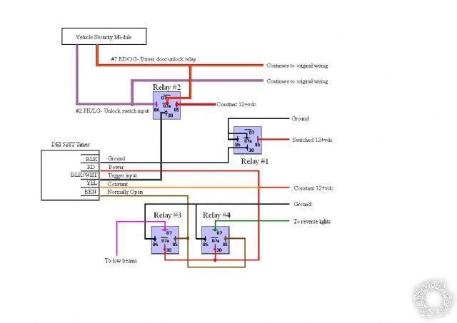
|