actuator to alarm problem
Printed From: the12volt.com
Forum Name: Car Security and Convenience
Forum Discription: Car Alarms, Keyless Entries, Remote Starters, Immobilizer Bypasses, Sensors, Door Locks, Window Modules, Heated Mirrors, Heated Seats, etc.
URL: https://www.the12volt.com/installbay/forum_posts.asp?tid=118379
Printed Date: March 06, 2026 at 9:10 PM
Topic: actuator to alarm problem
Posted By: asstpumpslimm
Subject: actuator to alarm problem
Date Posted: December 09, 2009 at 5:59 PM
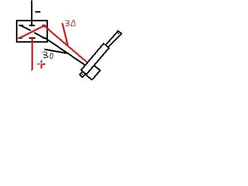
ok i want to hook the actuators on my trunk to my alarm channel 4 and channel 5 1 channel goes up and 1 channel goes down. i have a 6 pin switch wired to them now to use my trunk.
i use this diagram to wire everything up, quadruple checked wires. but when i connect the wires on the relays 1 wire from the 30 to 1 wire on the actuator. and the same with the other 30 to the other actuator wire.
when i hooked them up. i hit the manual switch in the car and no noise from the actuators and the trunk moved about 1 inch. i unhook the wires fro the 30 post and everything looks fine.
any help here
Replies:
Posted By: KPierson
Date Posted: December 09, 2009 at 6:22 PM
You can't parallel 5 wire connections you must series them - that may be part of your problem. Post up how your current switch is wired and we can tell you how to modify the above diagram to make it work. Most likely you'll have to disconnect the 87A pins from ground and connect them to the switch outputs. ------------- Kevin Pierson
Posted By: asstpumpslimm
Date Posted: December 09, 2009 at 6:54 PM
ok maybe you can get this picture, 6 prong switch power and ground in middle
2 wires coming off the actuators going to the 30 on the relays. i hooked it up just like the diagram
Posted By: t&t tech
Date Posted: December 09, 2009 at 7:02 PM
A six prong switch with power and ground in the middle, you have to verify if the switch is applying both power and ground when depressed or, if the wires rest at ground or twelve when the switch is inactiveand voltage is applied one way while the other leg sits at rest! ! After you have done this then we can help you! -------------
Posted By: KPierson
Date Posted: December 09, 2009 at 7:17 PM
What you should do is disconnect the switch all together and get the two relays working with the alarm. Then, rewire the switch to supply (-) outputs that connect to the relays (-) lock / unlock inputs. You should be able to just eliminate all the red lines above and connect the red actuator in the picture above to the other black pin (I hope that made sense). ------------- Kevin Pierson
Posted By: ckeeler
Date Posted: December 09, 2009 at 7:33 PM
i like the drawing of your actuator (im not kidding, i do), kinda cool. 
Posted By: asstpumpslimm
Date Posted: December 09, 2009 at 7:35 PM
ok, yes power and ground in the middle. power is straight to 12v source so i can use the trunk if the car is off, ground also grounded to body. press one way it goes up, pull it back the other way it goes down, the switch returns to rest in the middle bad pic but here it is 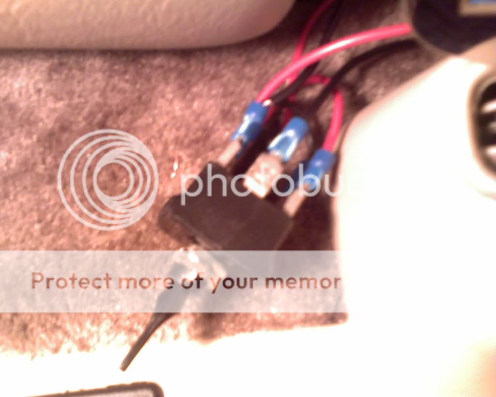
Posted By: asstpumpslimm
Date Posted: December 09, 2009 at 7:36 PM
thats my mad MS paint skills, i lost my picture it program where i could make something decent looking
Posted By: ckeeler
Date Posted: December 09, 2009 at 7:43 PM
i thought it was good. it takes me waaayyy too long to make something on paint that doesn't even look half that acurate.
Posted By: lspker
Date Posted: December 10, 2009 at 10:25 PM
Is it just me, or do you have the wire jumpered together? Try the out to the actuator on the centre terminals of the switch, and the powers on outsides. Uhm. but you will have power going straight to ground threw the relay. need to isolate better just to send -ve pulse to 86/85 as needed
Posted By: howie ll
Date Posted: December 11, 2009 at 1:53 AM
Try changing the 6 pin for a centre off 2 way momentary that's fed from ground, feed your alarm lock and unlock circuits to the switch contacts, assuming as in the diagramm that they are negative going. Do you need a few secsonds each way? If so you'd be better off with the alarm's aux outputs set as timed rather than the lock/unlock outputs. Diagramme stays as it is. That set up will give either your alarm OR the switch direct control. Before you join the alarm outputs to the switch, in line diode them (1N4004) with the bands towards the alarm. That will prevent relay feedback affecting the alarm's circuitry.
|