2000 nissian sentra remote start
Printed From: the12volt.com
Forum Name: Car Security and Convenience
Forum Discription: Car Alarms, Keyless Entries, Remote Starters, Immobilizer Bypasses, Sensors, Door Locks, Window Modules, Heated Mirrors, Heated Seats, etc.
URL: https://www.the12volt.com/installbay/forum_posts.asp?tid=118440
Printed Date: April 01, 2026 at 3:24 PM
Topic: 2000 nissian sentra remote start
Posted By: thejushinator
Subject: 2000 nissian sentra remote start
Date Posted: December 11, 2009 at 8:28 PM
Hello everyone new member here, let me assure you before making this post I did alot of searching (gained alot of new info) Ok I am planning on installing a remote start in a 2000 nissan sentra GXE, auto, keyless entry, no alarm system. Here is some info I got from searching on here: I'm 110% certain I have a chip in my key. Not all 2000-2006 Sentras were equipped with the Immobilizer system. The base models with the 1.8 engine didn't have it and neither did the base 2.0 models IIRC. My 2.0 model is the "sporty" version for the 2000-2001 line up and it did come with immobilizer as part of the sports package.
For the 2002-2003 Spec V models with the 2.5 L engine, I believe immobilizer came with the Rockford Fosgate premium package.
If I try to start my car with a regular hardware made key, I can sit there and crank all day but the motor won't turn over. I have to insert the chipped key before it will start. I am just looking to install a basic 1-way remote start system (2 way if the price is right). Dont need anything like an alarm or keyless entry (I could just continue using the keyless entry from my original fob) Ok I have a 1.8L engine so I presume I dont have an immobilizer system. Which means I dont need a bypass system, correct ? I have installed things such as aftermarket CD players, subs, speakers, etc.... I know installing a remote starter is harder than installing an aftermarket CD player, that is why I have came here for guidance. I have looked at the factory wiring diagram on here and know what all the color wires are, but where are they located ? Is installing a remote starter as easy as just connecting the right wires together (which would be info gained from the remote starters manual) ? Would systems like these be efficient for what I am looking to do? If these are not good any suggestions? https://cgi./Scytek-G40RS-Auto-Remote-Car-Starter_W0QQitemZ140352368875QQcmdZViewItemQQptZLH_DefaultDomain_0?hash=item20ada730eb https:////NEW-Remote-Start-Ready-Remote-Keyless-Entry-DEI-24923_W0QQcmdZViewItemQQhashZitem2557c7ef43QQitemZ160386510659QQptZMotorsQ5fCarQ5fTruckQ5fPartsQ5fAccessories
Replies:
Posted By: tommy...
Date Posted: December 11, 2009 at 9:02 PM
Posted By: thejushinator
Date Posted: December 11, 2009 at 11:04 PM
Posted By: thejushinator
Date Posted: December 12, 2009 at 12:38 AM
Sorry about that didn't really know what DMM meant. Yes I have a digital multimeter. Also this car has a tach in the dash, would I still have to run the wire out to the coil under the hood ? Sorry for all the questions just want to have all this stuff worked out in my head before I purchase the RS unit.
Posted By: thejushinator
Date Posted: December 12, 2009 at 5:59 PM
Ok, I read posts and reviews on here and felt confident that ultra start was a good brand. So I purchased an ultra start G11-XR unit. I know soldering is preferred for installation, but wouldn't a product like posi-tap (involves no cutting) work? Not confident with soldering and really dont want to risk it. I have been reading the install and owners guide for the past few hours, looks pretty straight forward. I just have to match up the g11-xr wires to the correct wires on my nissan sentra, correct ?
Posted By: t&t tech
Date Posted: December 12, 2009 at 6:12 PM
Don't use those wire taps! Take your time and strip and solder! That car is as easy as pie! Trust me i've done them by the thousands, literally! I only see one starter wire listed in the diagram, the right hand drive spec. i'm accustomed to have a second starter or cold start wire! Also a second ignition wire!
-------------
Posted By: kreg357
Date Posted: December 12, 2009 at 7:06 PM
1. Check to see if you need a bypass first. A plain key from WalMart is a good test without taking anything apart. 2. The perferred install method of professional installers is soldering. You don't want any cars coming back with problems. Any wires going to the engine bay should be soldered, like the Tach wire, due to moisture and vibration. 3. Always test and verify the wires you are going to attach to. The guides are nice but not always correct. Using a DMM protects the cars computer circuits ( doesn't draw current like test lights ). 4. If you need the bypass, mate the R/S and bypass prior to install. Usually you need +12 volts, ground, GWR from the R/S to the bypass. 5. Yes, you will have to remove some dash trim pieces to access the cars wires. Another source for wiring info is: https://www.bulldogsecurity.com/ Not listed above are your Power Lock & UnLock wires. The Ultra Start G11-XR supports these outputs so you might as well hook them up. It will do the power trunk release too, if your car has that feature. 6. Your car has 2 IGN wires. You will need to program the G11-XR for this. Menu 2 Option 1 set to 2nd IGN ( one flash). 7. There will be unused wires on the G11-XR. You don't need Diesel Wait to Start, Re-Arm, Dis-Arm, and Negative Parking Light. Horn is optional but nice. I would connect the Tach wire and run in Tach mode. It's much more reliable. All the other wires get connected. (Except the Red wire on the door lock harness.) 8. Plan on spending 6 hours doing the install. Try to keep all the wires neat. Buy some tie wraps. Use 3M Scotch Super 33+ Electric tape. Take you time and have fun. ------------- Soldering is fun!
Posted By: tommy...
Date Posted: December 12, 2009 at 7:32 PM
Worst case do the poke/wrap method if you are uncomfortable soldering...(although the best way to do it...) As tt said...Stay away from t-taps etc...especially in high current applications...(especially in the ignition harness connections...although they do sneak in sometimes with hard to reach wires...thats right i said it...... : 0...!) If the plastic portion is small... Most likely NO bypass needed...When you refer to a timer...Are you meaning a pre-determined run time... If so that is standard...Poke and wrap consists of stripping the insulation a 1/4 inch or so of the wire in the vehicle...Then use the tip of your test lead and push it through the center of the exposed wire...Halve the wire...Then strip the wire that is connecting to it back about 1" or 1" 1/2 inches...Push wire through just like threading a needle and wrap the remaining wire around til tight...On most Ultra Start the 2nd Ign wire is the default setting...Although verify for sure...Yes to the wal-mart thing...! Or just do install and see if it remote starts...If not put key in ignition and see if it remote starts...
-------------
M.E.C.P & First-Class
Go slow and drink lots of water...Procrastinators' Unite...Tomorrow!
Posted By: thejushinator
Date Posted: December 13, 2009 at 2:23 PM
Ok let me first thank everyone for your responses, without you help I wouldn't even be attempting this. Let me put how I think this will be wired and let me know how it looks, I will list the ones I know for sure first:
First will be the g11-xr then what it connects to on the car. Trunk release output (-) RED / white ------> Trunk release (-) Red @ hatch relase switch
Tach detection input (A/C) blue/white ---> Tach (any wire) @ ignition coil
Hood pin switch input (-) GREEN / WHITE ---> Drill under hood and connect it there
Park light output (+)10amp white --------> Parking lights (+) WHITE/ red @ drivers kick panel
System Ground input (-) black -----------> Ground somewhere on the body
Horn output (-) WHITE/ blue --------------> horn WHITE/ green (-) @ steering column harness
Brake Switch input (+) pink -------------> Brake RED / green (+) @ switch above brake pedal
Ignition output (+) blue ----------------> Ignition 1 BLACK/ Red (+) @ ignition switch harness
Door lock output (-) 250ma green --------> power lock Gray (type B) @SECU
Door unlock output (-)250ma blue --------> power unlock PURPLE / red (type B) @SECU Now below are the ones I have questions about:
Selectable output (+) white -------------> ???
12 volt input (+)30 amp red -------------> ???
12 volt input (+)30 amp red -------------> ???
Heater/Accessory Output (+) -------------> On the car their are two of these, which one do I connect to ?
Starter output (+) yellow ---------------> On the car their are two of these, which one do I connect to ?
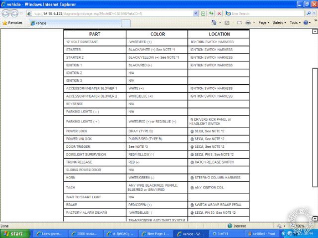
12 volt output (+)250ma -----------------> I assume this can be programmed to be the trunk release ? I have included pictures so it would be easier to help :) If there is anything else you need me to include please just ask. I dont want you to have to go look at the wiring diagrams or anything so if you need some other wiring diagram just let me know and I will go look it up and paste it here.
Posted By: kreg357
Date Posted: December 13, 2009 at 4:38 PM
Looks good so far. Now the fun begins... I checked 4 sources and got differences on each one. All having to do with the Start, IGN and ACC wires. This is where your DMM comes in. All sources say WHITE/ Red is Battery. There might be two wires there, both Whire/Red, or only one thick wire. Should show constant +12v. Hook up both Red heavy gauge wires from R/S here. (remove fuses first) Bulldog shows only one IGN, BLACK/ Red but AudioVox shows 2 IGNs, BLACK/ Red and BLACK / YELLOW, this site and Omega shows 2, BLACK/ Red & White. Test your car with the DMM. IGN is off with key out and on with key in Run & start position. BLACK/ Red is a good bet and if there is another it should test the same. For the Starter wire, Bulldog shows 2, BLACK/ White & BLACK / YELLOW. This site agrees but Audiovox shows only the BLACK/ White wire (but they have power going to the BLACK / YELLOW as IGN2.) Omega only lists one Starter wire, BLACK/ White. When tested, the Starter wire(s) will only show +12v with the key in the start position. Finally for the ACC wires Bulldog lists 2, White and WHITE/ Blue. Audiovox shows only 1, the White. This site shows only 1, the WHITE/ Blue (but lists the White as IGN2) and Omega agrees. ACC should test as +12v with Ignition switch On but 0v in the Start and Off positions. Test it. The results will tell use how to config the heavy gauge White wire coming from the Ultra Start (it can be IGN, ACC or Start). Additionally you might need to buy some +12v Bosch style relays to power up the extra wires. Anything on the immobilizer yet? ------------- Soldering is fun!
Posted By: kreg357
Date Posted: December 13, 2009 at 5:47 PM
Here is a link to the DEI Ready Remote Model 24923 R/S install guide. (The G11-XR install guide is very brief and assumes a lot.) While it was written for their R/S, the basics of locating and testing wires is presented clearly. They also go into detail on adding additional relays for IGN, ACC or Starter wires and have a nice write up on door locks. Makes for nice reading and will answer some of your questions and clear some things up. https://www.designtech-intl.com/pdf/manuals/24923.pdf ------------- Soldering is fun!
Posted By: thejushinator
Date Posted: December 13, 2009 at 8:34 PM
As far as the immobilizer goes, went to wal-mart and made a duplicate. Car started up fine with it. So no bypass is needed I assume.
I have seen a DMM in my garage hundreds of times, but now that I need it it is no where to be found. I hate that crap. So I will have to wait until I can find that or I will have to go out and buy one.
While we are talking about a DMM let me ask how to use one.... :)
I am assuming I touch the black (ground) to a ground on the car and the red wire on the DMM to the actual wire I am testing and check it. Is that correct ?
Posted By: tommy...
Date Posted: December 13, 2009 at 10:35 PM
As long as the wire your testing is 12 volts...If checking for ground...you would do the opposite...
-------------
M.E.C.P & First-Class
Go slow and drink lots of water...Procrastinators' Unite...Tomorrow!
Posted By: kreg357
Date Posted: December 14, 2009 at 7:28 AM
While testing wires, remember that most, if not all metal in the car is probably ground. After carefully testing/verifing each wire, temporarily wrap the exposed area with electric tape. Even though most metal is ground, you want to look for a good grounding point for the black wire from the Ultra Start. Look for one that Nissan supplied and used. Usually you will find a convenient stud with many other wires under the dash by the kick panel area. If you car is not equipped with an immobilizer that will save some time and money. Also you won't need the GWR wire on the Ultra Start (unless your car needs a KeySense signal, Nissans usually don't). While you are under the dash, look for a firewall hole with gromet that you can use to pass 2 wires thru. You will notice in the Ultra Start harness 2 very long wires. They are your Tach signal and Hood pin. Look from the engine side also. Sometimes the carpet or insulation covers them. The next choice is the door harness area. Last choice is drilling your own hole ( being extremely careful.) ------------- Soldering is fun!
Posted By: t&t tech
Date Posted: December 14, 2009 at 3:11 PM
I've looked at the u.s version wiring of this car, look basically the same as the ones i'm accustomed to! Everything you need is in the driver area, except tach! The lock trigger wires rest at around 4volts and pulse zero or ground when triggered, you can find these wires leading into the driver's door! when you remove the steering column an easy way to know if you have two starter wires and two ignitions is to count the wires, if you have six, then you have both second starter and ignition, if you have five you have second ignition most likely. (i've never seen one without second ignition) did one today, no second starter! -------------
Posted By: thejushinator
Date Posted: December 14, 2009 at 9:55 PM
Thank you T&T. Ok, you said the locks/doorlocks run to the door, but where did you splice into the door lock and unlock wires at? Which way did you route the tach wire to get into the engine bay ? 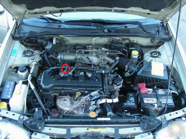
There are 4 ignition coils there, I have one of the wires circled, would that be a good place to 'splice' into it ?
Posted By: t&t tech
Date Posted: December 15, 2009 at 4:54 PM
On the left side of your picture, just behind the wheel arch, that harness leads into the interior passenger side, slit the grommet there, and feed your wires through! I'm not sure if i read you picture properly, but your'e not splicing any wires at the four spark plug connections, just behind there is where the four injectors are, you will locate the wire there, you can use any wire that is NOT COMMON at the injectors, i believe the common wire is RED / black, dunno if memory serves right there! The door locks run in the harness going into the door, this will be just under the bottom of the interior fusebox, the harness is secured to the base of the fusebox holder with a strap to the body, open this harness and test, they rest at four volts or so! From looking at that engine, looks pretty much the same to me! -------------
Posted By: t&t tech
Date Posted: December 15, 2009 at 4:56 PM
Also in reply to your pm, you need a relay for the second starter, you don't need to power up the other wires besides the BLACK/ red ignition wire, the rest just power up the a/c and the radio and other accesories! If however you would like to, the let me know, you would need another relay for this!
-------------
Posted By: thejushinator
Date Posted: December 15, 2009 at 7:26 PM
Once again let me thank you for your help. But your posts have made me think i am over my head again :( To tell the truth I really dont know what a relay is or how to wire one. 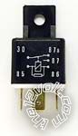
I searhed and that was a picture of a relay I found for remote starters..... Do I just attach the starter wire from the R/S to one of the connections on the relay then attach the two starter wires from the car to the other two connections on the relay ? I assume they would sell these at places like advance auto parts, correct? What would I ask for to recieve the right relay I am looking for. Yes I would like to power up the A/C or heat at remote start, I have to power that also? I just assumed that was heater /accesory output was for. There is one on the R/S and two on the car. So that would need a relay like above also, correct ?
Posted By: tommy...
Date Posted: December 15, 2009 at 7:36 PM
Most Ultra starts have a white wire that can do 2nd ignition,2nd accessory or 2nd starter(default is 2nd ignition)...All are 12 volt outputs...So unless there is more then 1 ignition...and the 2nd starter is +...you should be fine...! Relays are not bad...! ------------- M.E.C.P & First-Class
Go slow and drink lots of water...Procrastinators' Unite...Tomorrow!
Posted By: thejushinator
Date Posted: December 15, 2009 at 8:15 PM
Ok, I think i get what you are saying tommy. 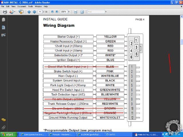
Above is the wires on the R/S I purchased Lets say that the car has 2 starter wires and 2 ignition wires. Here is how I would wire the ignition and starter. The R/S wire yellow is the starter wire, so it would go to the one of the starter wires on the car. But the car has two starter wires. So that means I would take one of the 12 volt input wires from the R/S (red) and connect it to the other starter wire on the car, is this correct ? The same goes for the ignition. Lets say the car had two ignition wires. I would take the blue iginition wire from the R/S and connect it to one of the ignition wires on the car. Then I would take the other 12 volt input wires from the R/S (red) and hook it to the other ignition wire on the car, is this correct ?
Posted By: kreg357
Date Posted: December 15, 2009 at 8:56 PM
No. The two Red wires are inputs TO the R/S. The R/S start uses those to supply the onboard relays to give the IGN, ACC and Start outputs as well as power itself and control the other functions and outputs ( horn, locks, alarm, etc.). The extra relays mentioned in an earlier post will be used to supply the cars additional needs ( ACC2, Start2, etc). Did you download and review the Ready Remote install guide? It has some good wiring diagrams of the extra relays sometimes required for a R/S install. If as T&T says, your car has 1 Start, 1 ACC and 2 IGN's, the G11-xr can handle that without any extra relays. If the Bulldog info you posted is correct then you will need 2 relays to supply the 2 ACC's and the Ultra Start will handle the 2 Start's with its Selectable (White) output.
-------------
Soldering is fun!
Posted By: thejushinator
Date Posted: December 15, 2009 at 11:12 PM
I never even saw that post on page 2. Just went back and looked at that install guide and boy it is like night and day. That has really helped. I looked at the relays in that guide and it helped just a few questions. 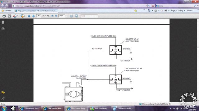
1. The +12 vdc constant (fused 20a), do those go up the constant power (the same place as the two red constant power wires) ? The ground goes to the same spot as the ground as the R/S also i assume. 2. Lets assume I need these when the R/S comes in, what kind of relays do i go to advance auto parts and ask for ? 3. How do i get 20A fuses on the wires that are going to the constant power ? 4. What guage wire do i look for to connect the relays ? Sorry for all the questions :) But in all seriousness that install guide on page 2 is AWESOME, has helped me leaps and bounds.
Posted By: t&t tech
Date Posted: December 16, 2009 at 7:07 PM
1) Yes 2)Single pole single throw or single pole double throw, doesn't matter! 3)Purchase a blade fuse holder with a couple twenty amp fuses! 4)Purchase relay sockets, these wires will be already suited to the current requirements of the relay! -------------
Posted By: kreg357
Date Posted: December 16, 2009 at 7:40 PM
Glad to hear the guide helps. Basically the output from the R/S actuates the two relays. This allows for 2 independant and isolated outputs to power the appropriate wires at the cars ignition. 1 Yes ( If there is only one 12v constant power wire at the cars ignition switch, it was supplying all the power to each of the circuits normally.) 2 12 volt SPDT 30/40 Amp relays plus the 5 wire harness. There is a good info section on relays on this site. I get mine in bulk, prices around $2.25 each, including harness. Store price for small quanity probably about $9 each... 3 WalMart has inline automotive fuse holders. You can use the old style Buss glass tube style ( AGC ) or the newer ATC style. ( Might as well get a soldering gun while you are there.) 4 Get the relay with the 5 wire harness. The wires are the proper guage and usually about 8 to 12 inches long. On the G11-XR you will be able to get by using the Default options with the possible exception of Menu 2 Opt 1. That will depend on the Sentra's wiring needs. Also Menu 2 Opt 4 can be changed to Car Finder. Set up like that, the # button, when pressed for 3 seconds, will flash the parking lights and beep the horn 5 times. You will still be able to pop the trunk by holding the UnLock button for 3 seconds. Your next step is to take a peek in the streeing column at the ignition switch to see if the wires match up to the Bulldog wire list. And of course, even if they match up exactly, it is wise to test and verify with a DMM. You might get lucky and not need any extra parts. ------------- Soldering is fun!
Posted By: thejushinator
Date Posted: December 18, 2009 at 6:41 PM
Ok I borrowed a DMM today from a friend of mine. I didn't know which setting to put it on. Here is a picture of it if anyone could help me.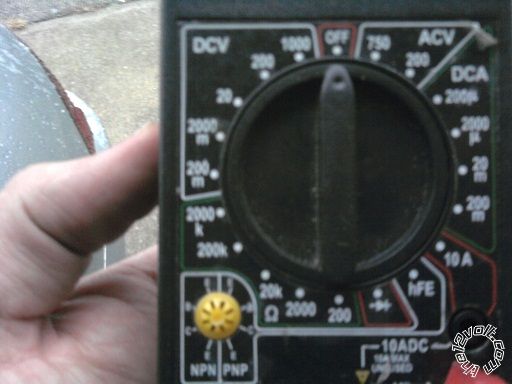 Also I started taking apart the steering column today to check everything out (R/S should be here tomorrow) and there are 6 wires. So it looks like I will be needing to do a relay. Not much extra wire there to pull on so it is going to be tight. kreg357, could u link me to the relay info on here, I can't seem to find it.
Posted By: tedmond
Date Posted: December 18, 2009 at 8:41 PM
turn the dial to the left under DCV and leave it at 20. Is that digital? if it isnt, sometimes the analogue meters cant read quick enough. as for relay wiring for additional start, acc, or ign 85 - dedicated (-) function from start/alarm
86 - constant 12v
87 - constant 12v fused @ 20 amps
30 - to wired on car depending on function of (-) output from rs connected to 85.
Posted By: thejushinator
Date Posted: December 18, 2009 at 9:12 PM
Yes it is digital. Tedmond, the picture above says just one goes to: constant 12v, one to ground, and then one to the wire on the car....... BTW, u have 85 to dedicated (-) i assume that is the ground ?
Posted By: kreg357
Date Posted: December 18, 2009 at 9:30 PM
Set the DMM to the DCV 20 position. This means you are looking for a DC voltage below 20 volts. Plug the test leads into the Ground and Red jacks. Test this setup by touching the leads to the cars battery terminals. You should see around 12.3 volts. Test leads with aligator clips are handy for checking the Start wire... The sites Relay section can be found with this link: https://www.the12volt.com/relays/relays.asp It has the pin outs and a nice internal diagram of the relay. Follow the Ready Remote guide for the actual connections to the the Ultra Start and the cars ignition wires. Remember to allow space for things like Tilt / Telescopic, steering shaft rotation and trim covers in the steering column area. Don't secure everything until you test. Tie wraps are the preferred method to position & secure your wires. After you get all the connections made, insert the R/S's fuses in the red power wires. The cars parking lights should flash and the horn should beep. (Parking light and horn connection good ) The 2 transmitters should already be programmed to the G!11. Next try the Lock and UnLock buttons on the R/S transmitter. ( Lock and UnLock connections good ) Hold the UnLock button for 3 seconds and the trunk should release. ( Trunk release good ) At this point you should program the G11's Selectable Output (white wire). I believe it defaults to IGN but set it for what ever your car needs. ( Programming will also verify your IGN1 connection ) Before you can do an actual remote start, you must Tach Learn the Ultra Start controller. Insert the key and turn the switch to ON. The R/S will turn the cars parking lights on to signal it is doing a tach learn. Start the car with the key. Within 20 seconds the parking lights should flash and the horn should beep 3 times to signal a successful tach learn. ( Good tach signal and Start connection ) Turn the car off and remove the key. Make sure the hood is closed and press the Start button. The car should start. Listen for over / under crank. Ideally the R/S should be tach learned with a warm engine and you can do that with the Optional Tach Learn procedure outlined in the G11 install guide later. Do a Key Take Over. Start car with R/S transmitter, after the parking lights flash and come on steady insert key and turn to ON. Step on the brake pedal. The car should continue to run. Try the Pit Stop function. With the car running with the key, in park & your foot off the brake, press the R/S start button and then remove the key. The car should continue to run for 15 minutes. Next, press the brake pedal with the car running under a remote start. It should shut down. Remote start the car again and pop the hood. It should shut down with the hood open also. These are important safety features all R/S installs should have. Have a successful Saturday! ------------- Soldering is fun!
Posted By: t&t tech
Date Posted: December 18, 2009 at 9:31 PM
No that 85 isn't dedicated to ground in tedmond's description! That's the trigger for the respective output! Here's another way Pin 85- ground pin 86- To starter wire or accesory pin 87 - fused twelve volts at 20 amps pin 30- to the respective wire depending on where you connected 86 (meaning if you were connecting second starter relay, pin 86 would go to the first starter and pin 87 to the second starter) Drawback to this is they will be powered with or without the remote start. -------------
Posted By: t&t tech
Date Posted: December 18, 2009 at 9:32 PM
Sorry kreg, i posted while you were!
-------------
Posted By: kreg357
Date Posted: December 18, 2009 at 9:43 PM
T & T, We overlapped the other day too. I am a very slow typist.............. I believe he said 6 wires at switch, just like you said for those cars with the steering wheel on the wrong side........ ------------- Soldering is fun!
Posted By: tommy...
Date Posted: December 18, 2009 at 10:05 PM
Remember you can use the White wire in the r/s's ignition harness to do 2nd ignition or 2nd starter...So you should only need One relay...
-------------
M.E.C.P & First-Class
Go slow and drink lots of water...Procrastinators' Unite...Tomorrow!
Posted By: thejushinator
Date Posted: December 18, 2009 at 10:23 PM
Yea that is what I was going to do. Car has 2 starter wires and 2 ign wires. So I will just use the white wire for 2nd ignition and use the relay for the 2nd starter wire.
Posted By: thejushinator
Date Posted: December 18, 2009 at 11:20 PM
Ok, I checked out the relay "basics" Here are some things I am still unclear about. In the install guide that is on page 2 is shows that you have to use 2 relays to "split" a wire. 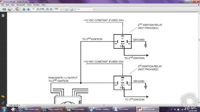
Earlier in this thread tedmond and T&T stated how I could make it with one relay. To tell the truth I really didn't understand what you were saying with input and output and such, so I tried to dummy it down for me. Here is a picture of it: 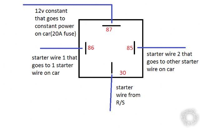
Sorry for all the pictures I am a visual learner. Is this what it looks like or am I tottal wrong? Again thanks for all the help, hopefully I will have all of this stuff down by the time it arrives tomorrow so I can get right to work.
Posted By: kreg357
Date Posted: December 19, 2009 at 8:51 AM
Your relay wiring won't work. Your goal is to make 2 independant/isolated +12v Start outputs from the Ultra Starts one (yellow wire). While it costs more to use 2 relays & fuses and takes up more space under the dash, it is the safest way to do it. On the relay, pins 85 and 86 need a +12v and a ground to actuate the coil and energize the relay. They are not outut pins. Either can be the trigger. Meaning you can hook 86 to constant battery and use the R/S GWR output to trigger the relay or you coluld hook pin 85 up to ground and use +Start on pin 86 as the trigger. In your case the trigger has to be the Start signal. If you look at the Ready Remote diagram you posted above, that is what they are doing to create two IGN outputs with the R/S's IGN output. You will be doing the same thing with the G11's Start output to create 2 Start signals for the car to use. A SPDT relay, while de-energized has pins 30 to 87A connected ( aka Normally Closed ). When energized, pin 30 goes to pin 87. Think of it as a switch. In its non enegized state the electricity flows from pin 30 to 87A. When energized, it switches over and flows from pin 30 to 87. Pins 30, 87 and 87A are for high current and the current can flow either way ( 30 to 87A or 87A to 30, etc). ------------- Soldering is fun!
Posted By: thejushinator
Date Posted: December 19, 2009 at 5:23 PM
Ok I got everything wired but I couldn't get it to Tach learn. I used a non common wire at the ignition coil which was advised for me to do. The only thing I can think of was there was a weak/no connection on the tach wire.
When I tried to do the Tach learn I got the parking light flash to let me know it was in tach learn mode. I then started it and let it run for a minute or so but I never got the 3 flashes for a successful tach learn. I reset the R/S and tried it again but no luck.
I was curious if the car would start anyways so I tried remote starting the vehicle. It wouldn't crank or do anything. I know I am going to have to try and figure out the tach learn. But shouldn't it atleast try to grind and start, or without tach learning does it not even try to start ?
Thanks for all your help everyone.
Posted By: t&t tech
Date Posted: December 19, 2009 at 9:23 PM
Not familiar with the unit you're using, but does anything power up?, accesory or ignition lights?, one thing on this vehicle is that the ignition must be powered for the starter to crank!
-------------
Posted By: thejushinator
Date Posted: December 20, 2009 at 12:13 AM
No, nothing powers up as far as the heater or anything like that when i try to remote start. I worked on it about 5-6 hours today and then decided to call it a day. The R/S is getting power because the park lights work and the antenna lights up also.... In the install quide it says the unit must be tach learned before remote starting. So maybe it wont even let u attempt a remote start until it is tach learned..... ??? I really dont know. I am going to try another ignition coil tomorrow and see if that helps any. If that doesn't fix it I am stumped.
Posted By: thejushinator
Date Posted: December 20, 2009 at 12:46 AM
TT, I was just rereading your post, what do you mean the ignition has to be powered up for it to crank ?
Posted By: kreg357
Date Posted: December 20, 2009 at 1:28 AM
If everything else works, parking lights flash, door lock & unlock and you can do a successful G11 reset, then you are doing very well! I believe the issue is the way the G11 actually Tach Learns. Does the car flash its parking lights 7 times after you press the transmitters Start button? That means it hasn't done a tach learn yet and won't even try to do a remote start. Its a long explaination but all you have to do is an Optional Tach Learn as described on page 6 of the install guide. If you wired the G11 Start output (Yellow wire) to the 2 relays as shown in the Ready Remote guide, then the G11 has no direct connection to the cars start wire. The G11 actually monitors its yellow start wire to "see" the car get started and then checks the Blue/White Tach wire for a valid tach input. If the G11 never sees the yellow start wire go to +12 volts (while you have the key turned to the start position) it will never complete the tach learn. You can check the tach signal from the ignition coil with your DMM. Switch the selector switch over to the ACV area to a voltage that can read something in the range of 0.5v to 6 volts. Then black probe to ground and red probe to the tach wire (Blue/White) with the engine running. ------------- Soldering is fun!
Posted By: t&t tech
Date Posted: December 20, 2009 at 6:28 AM
If the ignition is not powered properly, the starter will not crank! In most cars even though ignition is unpowered the starter will still crank but the car won't start, not the case with your vehicle, the igniton must be on to allow cranking of the motor!
-------------
Posted By: thejushinator
Date Posted: December 20, 2009 at 9:12 AM
T&T tech, I am really not sure what you mean. I have ignition wire one hooked up to the Blue wire on the R/S and ignition two wire hooked up to the White wire on the R/S. Is that what you mean ? Or do I have to someone hook the ignition wires to a 12v constant ? I am getting ready to go back at it. Going to give it another 3-4 hours and see if I can get it working, if not I dont know what I will do.
Posted By: t&t tech
Date Posted: December 20, 2009 at 9:15 AM
NO, you don't have to connect the ignition to a constant source! That info was just so you would know! -------------
Posted By: thejushinator
Date Posted: December 20, 2009 at 11:50 AM
Hey everyone, it is up and running. Took about 30 min today, guess what was wrong................. I didn't have the remotes programed into the g11-xr, DUH (I thought they were pre-programmed) As soon as I programed those in and hit the start button it fired up perfect. Once again I would like to thank everyone who helped me. Thanks guys.
Posted By: t&t tech
Date Posted: December 20, 2009 at 12:48 PM
Congratulations! Glad to know we could help! -------------
Posted By: thejushinator
Date Posted: December 20, 2009 at 8:28 PM
Oh no, I guess I spoke too soon. I checked everything before I tucked all the wires away and the car started fine. I wrapped all the wires up good and tight and put them under the steering column on the car. I then tested again to make sure it was still functioning. Wouldn't start. the park light would flash and the heater would come on then the guage would light up like it was going to start but it wouldn't attempt to crank. That was followed by 5 flashes of the parking light. So I checked the owners manual: 5 slow flashes: ignition on during start attempt (key not in ruled that out) 5 flashes: hood pin open (Checked, rechecked, and rechecked again, was functioning properly, no problems there) So I was stumped on what the problem could be, I then opened up the install guide and it had different problems if the parking lights flased 5 times: 5 slow flashes: Ignition on during start attempt (Once again key not in ignition, ruled it out once again) 5 flashes: Brake pedal shutdown Ok, so I have ruled out all other options, but I really dont know what brake pedal shutdown means. Does that mean the brake pedal is engaged during startup ? I checked multiple times the brake wasn't pressed down at all during startup. Can anyone point me in the right direction on what to be looking for with this problem ?
Posted By: tedmond
Date Posted: December 20, 2009 at 9:20 PM
the brake wire will show 12v when it is pressed. did you test the brake shutdown wire that you tapped into at the brake pedal? the shutdown wire is used to dissengage the remote start if someone was to hop into the car without the key and try to shift into gear. probe the rs ignition wires again and verify they are not on constant 12v lines on the car. the wiring guide is nice, but they are not always correct. you have to verify by testing with a dmm
Posted By: thejushinator
Date Posted: December 20, 2009 at 10:24 PM
I think that could be my culprit. So the wire I tap my brake wire into should show 0v at rest and 12v when the brake is pressed. Is that correct ? If so I will check and make sure I tapped into the correct wire. I really didn't know how to check the brake wire so I just went by the guide.
Posted By: tommy...
Date Posted: December 22, 2009 at 11:18 AM
If the lights on the dash are coming on...Its just not cranking...Look at the starter and second starter wires , checking for power and output at the connections(on both the remote start and car)......The 2 - 12 volt leads from the ignition harness on the Remote Start that are connected to the vehicles Ignition harness...Check connection and power at connection and remote starts plug/harness...One is for system power and the other is for starter crank...Which wire did you add the relay for...? 2nd starter or 2nd ignition...Check that relay too...! There wasnt a bypass,if i remember from earlier...Usually the brake input will not let the vehicles dash lights to come on...and the cars heater to blow...But usually the remote start just wont respond or Parking lights just flash...!
-------------
M.E.C.P & First-Class
Go slow and drink lots of water...Procrastinators' Unite...Tomorrow!
Posted By: tommy...
Date Posted: December 22, 2009 at 11:21 AM
t&t tech wrote:
If the ignition is not powered properly, the starter will not crank! In most cars even though ignition is unpowered the starter will still crank but the car won't start, not the case with your vehicle, the igniton must be on to allow cranking of the motor!
------------- M.E.C.P & First-Class
Go slow and drink lots of water...Procrastinators' Unite...Tomorrow!
Posted By: thejushinator
Date Posted: December 23, 2009 at 9:49 PM
Tommy, it was working fine before i tucked all the wires up into the car. Its not like it never worked. That is why I am thinking something just came loose. I really can't look at the moment (just had tonsils taken out monday) but when i get well again I will check everything back out.
Posted By: tommy...
Date Posted: December 24, 2009 at 8:34 AM
thejushinator wrote:
Tommy, it was working fine before i tucked all the wires up into the car. Its not like it never worked. That is why I am thinking something just came loose. I really can't look at the moment (just had tonsils taken out monday) but when i get well again I will check everything back out.
Dont think i ever mentioned that it worked or not...The tips i gave you WOULD be a symptom of pulling a wire loose...Im just telling you where to start looking for this "loose" wire...! ------------- M.E.C.P & First-Class
Go slow and drink lots of water...Procrastinators' Unite...Tomorrow!
Posted By: thejushinator
Date Posted: December 24, 2009 at 1:41 PM
Oh, ok thanks. Sorry for that, I thought u meant something else. Thanks for the help.
Posted By: thejushinator
Date Posted: December 24, 2009 at 4:23 PM
Ok I think I figured out what went wrong. I think I had the relay to the 2nd ignition wired wrong. Let me go over how I have it wired. No that 85 isn't dedicated to ground in tedmond's description! That's the trigger for the respective output! I used T&t's explanation below: Here's another way Pin 85- ground pin 86- To starter wire or accesory pin 87 - fused twelve volts at 20 amps pin 30- to the respective wire depending on where you connected 86 (meaning if you were connecting second starter relay, pin 86 would go to the first starter and pin 87 to the second starter) Drawback to this is they will be powered with or without the remote start. Here is what I made with those directions: 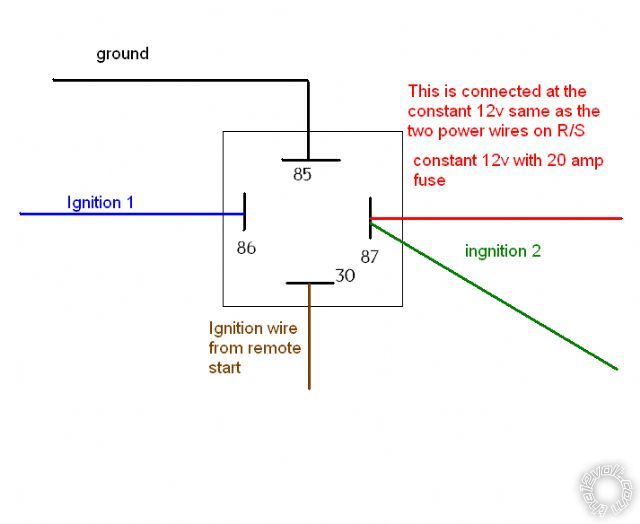
Is that relay wired up correctly to work ? These relays will be the death of me......
Posted By: thejushinator
Date Posted: December 26, 2009 at 10:14 PM
I know you guys explained relays to me time and time again, but I have read each response concerning relays 10 times, I am lost. I only have one relay (that is all they had at advance auto parts) which is the only place around me that has any. I went back today they still dont have any and thye said will take 4-5 days til the truck comes it til they get more. I know how to do it with 2 because I have a picture using two. But it was stated in here it can be done with one relay which I have. Is the picture above correct ? If not, what needs to be changed ?
Posted By: t&t tech
Date Posted: December 27, 2009 at 10:10 AM
Why is ignition 2 connected to pin 87? Connect the ignition 2 wire of the car to pin 30, exclude the wire from the remote starter that is on pin 30 and the rest remains as is! -------------
Posted By: thejushinator
Date Posted: December 27, 2009 at 12:05 PM
Thanks for your help, here is what I have now: 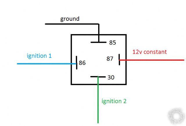
Ok, so i assume I attach the ignition wire from the remote start to either of the ignition wires of the cars wiring harness correct ? Then I connect the relay ignition wire 1 on the relay to the same ignition wire that the remote start is hooked up to. Then take ignition wire 2 from the relay and connect it to ignition wire 2 on the car. The relay I purchased didn't have a harness or a harness I could buy for it so I just purchased some 18g wire.
Posted By: t&t tech
Date Posted: December 27, 2009 at 2:20 PM
Yes you are correct in your assumptions! Also you should use at least twelve gauge wire for the purpose that the relay is going to be serving! -------------
Posted By: thejushinator
Date Posted: December 27, 2009 at 4:47 PM
Looks like I will have to go back and get some 12g wire then. Thanks.
Posted By: JWorm
Date Posted: December 27, 2009 at 4:53 PM
Don't worry about upgrading the wire size for 86 and 85. Those are low current. 22 gauge would even work fine.
Posted By: t&t tech
Date Posted: December 27, 2009 at 5:19 PM
Yeah forgot to mention that!
-------------
|