2010 ford fusion, viper 5901
Printed From: the12volt.com
Forum Name: Car Security and Convenience
Forum Discription: Car Alarms, Keyless Entries, Remote Starters, Immobilizer Bypasses, Sensors, Door Locks, Window Modules, Heated Mirrors, Heated Seats, etc.
URL: https://www.the12volt.com/installbay/forum_posts.asp?tid=118473
Printed Date: March 30, 2026 at 3:31 PM
Topic: 2010 ford fusion, viper 5901
Posted By: monty862
Subject: 2010 ford fusion, viper 5901
Date Posted: December 13, 2009 at 1:20 AM
Hi guys. I have a Viper 5901 I am installing it in a 2010 Ford Fusion. I have found a good spot to mount the main unit and thought I'd start with the Heavy gauge remote start (H3) 10 pin wiring harness first. The Viper harness diagram is as follows for the harness: o H3/1 Pink (+) Ignition 1 Input / Output
o H3/2 RED / Wh (+) Fused 30A Ignition 2 / Flex relay input 87
o H3/3 Orange (+) Accessory Output
o H3/4 Violet (+) Starter Output (harness side of starter kill wire)
o H3/5 Green (+) Starter Input (key side of starter kill wire)
o H3/6 Red (+) Fused 30A Ignition 1 Input
o H3/7 Pink/Wh (+) Ignition 2 / Flex relay output
o H3/8 Pink/Blk (+) Flex Relay Input 87A key side (if required) of flex relay o H3/9 RED / Blk (+) Fused 30A Accessory / starter inputo H3/10 N/C not used The Fusions ignition switch harness has a 7 pin plug. There are 6 wires in the 7 pin plug. The wiring diagram shows what 5 of them are. I'm not sure of the sixth. Here is the fusion wiring diagram: | Battery | | BLUE/RED | | (+) | | IGNITION SWITCH HARNESS | | |  | Ignition 1 | | WHITE/ ORANGE | | (+) | | IGNITION SWITCH HARNESS | | | | Accessory 1 | | VIOLET/GREEN | | (+) | | IGNITION SWITCH HARNESS | | | | Starter 1 | | BLUE/WHITE | | (+) | | IGNITION SWITCH HARNESS | | | | Anti-Theft Type | | FORD PATS® OR SECURILOCK® VEHICLE IMMOBILIZER | | | | Anti-Theft Descript | | THE KEY SENDS AN RF SIGNAL TO THE BCM MODULE THROUGH AN ANTENNA LOCATED AROUND THE IGNITION CYLINDER | | | | Key Sense | | BLUE/GRAY | | (+) | | IGNITION SWITCH HARNESS |
I have tested and verified the function of the wires on the ignition harness. I'm still trying to figure out what the sixth wire is. The terminology that Viper uses is a little confusing to me and I am hoping you guys can steer me as to which wires from the H3 go to which wires on the ignition harness. Have no idea what a flex relay 87 is for. I believe I have to cut the Blue/White starter wire and use the Violet and Green wire from the H3 on it. I'm not certain on which accessory wire to use on the H3. I will run a wire from the battery for 12 volts if that is the best method. Hope to hear from you soon! -------------
Replies:
Posted By: monty862
Date Posted: December 13, 2009 at 2:24 AM
Oh, I forgot to mention I can't believe how small the wire gauge is on the Fusion ignition harness. I have installed two Bulldog systems years ago and the wires were a lot bigger on those cars. The Vipers harness wires look twice as thick!
-------------
Posted By: monty862
Date Posted: December 13, 2009 at 11:56 PM
I have tested the unlisted wire in the diagram.2010 Fusion- Ignition Harness-7 pin plug - pin number 3 is 12 volts constant. It appears to be grey with a brown or possibly black stripe. Don't know why its not in the diagram. Still hoping to hear from you guys on the wire connections on the H3 harness. Thanks
-------------
Posted By: monty862
Date Posted: December 14, 2009 at 12:09 AM
 -------------
Posted By: chev104275
Date Posted: December 14, 2009 at 6:46 AM
(GY-BN) 18 CTRL MOD. - POWERTRAIN # TRANSMISSION RANGE OUTPUT PARK (TRO-P)
it goes to the floor shifter
-------------
If i Can't Install it I Don't need it Joe
Posted By: monty862
Date Posted: December 15, 2009 at 7:34 AM
Thanks Chev. I didn't think to check it after changing gears. Sure enough, 12 volts when in park, 0 in the others. I would have thought that it would show 12 volts in neutral also, but it doesn't. It will start in neutral though.
-------------
Posted By: monty862
Date Posted: December 15, 2009 at 8:22 AM
OK. Since I haven't gotten any responses on the remote start heavy gauge wiring, here is what I am thinking is correct. If you guys could, does this sound correct to you. Viper H3-1 Pink to Fusion pin-1 ignition 1 WHITE/ orange.......Viper H3-2 RED / White not used......... Viper H3-3 Orange to Fusion pin-6 accessory violet/green.......................Viper H3-4 Violet to Fusion starter side of cut wire pin-7 blue/white........................Viper H3-5 Green to Fusion key side.of cut wire pin-7 blue/white...............................Viper H3-6 Red to Fusion Battery or pin-4 blue/red...............H3-7 & H3-8 Pink/White - Pink/Black not used................Viper H3-9 RED / Black to Fusion Battery or pin-4 blue/red.......................This is how I see it. If any of you guys with install experience see it different please let me know. I'm probablt going to start my wiring this weekend. I thought I would post my progress and installation pics as I go along to possibly help someone else doing a Fusion / Milan. Thanks in advance.
-------------
Posted By: 05gt
Date Posted: December 15, 2009 at 10:24 PM
main harness wiring for 2010 fusion H3/1 Pink will go to ignition 1 in the car (WHITE/ orange) H3/2 Not needed H3/3 Orange will go the accessory 1 in the car (PURPLE / green) H3/4 Violet will go to the starter wire in the car (blue/white) H3/5 Green Not needed (your car already has a factory immobilizer) H3/6 Red will go to 12 volts in the car (there are two 12 volt wires at the SJB that supply 60 amps each, connect one of your power wire from the viper brain to the thick yellow/red and the other from the viper brain to the thick RED wire) H3/7 Pink/white (not needed) H3/8 Pink/black (not needed) H3/9 RED / black (12 volts in the car) (refer to H3/6) make sure you test all wires prior to hooking them up
Posted By: monty862
Date Posted: December 16, 2009 at 2:28 AM
Thanks for verifying. I wasn't sure that I wanted to cut that starter wire anyway. I was thinking I would just use the H3 Violet and splice into the Blue/White starter wire. One less thing to go wrong and prevent the car from cranking. Is there any advantage using the two wires in the SJB over running a Heavy fused wire from the battery? I was planning on running it in the cabin with the siren and hood pin wires. Thanks again! -------------
Posted By: monty862
Date Posted: December 16, 2009 at 2:39 AM
Afterthought: I think that even though the car has an immobilizer, If I cut the starter wire and wire up both sides of it, it would prevent someone from starting the vehicle even if they have the key, IF the alarm was activated. Still probably won't wire it that way though. If they have my key they probably are going to have my remote too.
-------------
Posted By: 05gt
Date Posted: December 16, 2009 at 6:33 PM
there is no advantage of using the 2 12 volt wires at the SJB, go to the battery if you want, the SJB 12 volt wires can handle what you are connecting to them
Posted By: monty862
Date Posted: December 29, 2009 at 12:57 AM
Well I finally got around to wiring up the ignition wires. Four connections at the ignition switch: Ignition wire(Viper and Fortin), Accessory wire & Starter wire. On the starter wire I only went with the Violet (starter side) wire. Cons: I lose the starter kill and anti-grind by wiring this way. Pros: Don't have to sever the cars starter wire and a splice repair would not be needed if ever wanted to remove system and although unlikely, a malfunction in Viper unit can't leave my wife stranded. I know its kinda silly to not want to sever the wires but I'd rather not compromise the vehicles wiring harness. 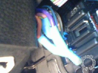 I also connected the two Fortin bypass wires RX and TX to the transponder connection. 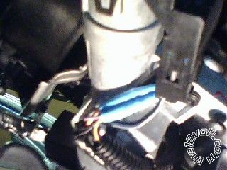 All connections were soldered, used heat shrink to seal and were loomed. I need to hook up three 12 volt constants to battery or SJB, hood pin, brake pedal input and the blue wire from the Fortin to the correct neg. output from the 5901 and I should be able to fire this puppy up. Like I said before, I'm doing this to hopefully help others with a Fusion/Milan install. I know I'm going to need more help myself before its over. If you guys see any mistakes please let me know and I'll make corrections. Thanks, and I'll update as progress occurs. -------------
Posted By: monty862
Date Posted: December 31, 2009 at 11:00 PM
Two shots of the SJB feed. 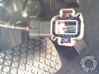 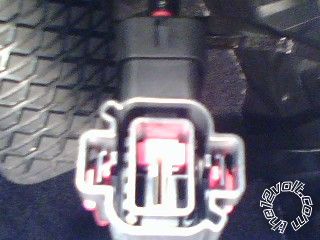 -------------
Posted By: 05gt
Date Posted: December 31, 2009 at 11:44 PM
sorry, 2010 has changed from 2009 is that a picture of connector G in that picture, that one is rated at 120 Amps, which is way more than enough to handle what you are doing in 2009 there is a 2 pin connector lower down on the SJB that has the 2 12 volt wires on it, they were rated at 60 AMPS each I guess they just combined everything to 1 wire in 2010 If that is connector G and it is a red wire you will be fine to connect to that
Posted By: monty862
Date Posted: January 01, 2010 at 4:31 AM
Thanks for the clarification.. I fabricated a bracket for the siren tonight, so that I could put it where it needed to go. I had to take the battery out to get a good look at the firewall for the siren & hood pin feed. Now that its out, I think I've talked myself into the battery feed again. I've never had a car with the engine bay as packed as this one. Got the 3.5 V6 and it is shoe horned in there. Surprisingly, there is a lot of room under the instrument panel. I appreciate your quick reply. Happy New Year!
-------------
Posted By: monty862
Date Posted: January 26, 2010 at 6:53 AM
I finally have everything wrapped up under the hood. Fabricated mounting brackets for the siren and hood pin and got them installed. 8 gauge wire fused at 60 amps from + battery cable and 12 gauge wire from - battery cable pigtail/body mount. All wiring soldered, loomed and ran into cabin through grommet in plastic firewall plug. I am about to start on the H1 harness from the Viper 5901. I have a question I could use some help with. I know that I won't be using the H1-9 BLACK/ white Dome light supervision wire. I also won't be using the H1-10 WHITE/ blue Turbo Timer wire. My question is in regards to the H1-4 WHITE/ brown Light Flash Isolation wire. Does my vehicle have this multiplex circuit? It doesn't seem to state it anywhere I can see on the install sheet. The sheet has parking lights listed twice. Once as - and again at +. Under the negative listing the sheet does state "may need to interrupt the headlight switch ground wire when triggering this wire. It is BLACK/ purple at the headlight switch. 10 pin plug, pin 3. See tech doc 1096 for wiring information'. Anyone know what tech doc 1096 states? Thanks for your replies. 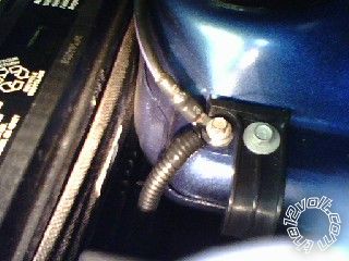 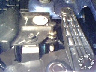 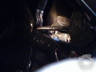 -------------
Posted By: t&t tech
Date Posted: January 26, 2010 at 6:20 PM
if your install lists this for the negative trigger wire, if you will be using this wire, chances are you will need to isolate from the stalk, just cut the wire in half, the side from the stalk to the WHITE/ brown and the other side to the white parking flash wire,
-------------
Posted By: monty862
Date Posted: February 10, 2010 at 11:23 PM
Finished up the remote start portion of my install tonight. Fired right up. This may be the longest install in history, but I'm in no hurry, as this is a car we only drive on the weekend. I'll post more install pictures soon. Quick question for you pros. I ran a feed from the battery to a terminal post under the dashboard. All my 12v connections are powered from this post. Two from the H3 heavy ignition harness (actually three, went ahead and wired up the flex relay lead even though it wasn't needed at this time. I just left the fuse out of it.) One from the H1 Viper control unit and One from the bypass module (W2W). My question is; what amp fuse would you go with on the 8 gauge wire from the battery? The wire came with an inline fuse holder and a 60 amp fuse. I don't think it would pull anywhere near that much amperage. My cars ignition wires are very small compared to the Viper's harness wires and I'm sure they must use relays for all of them. I'm thinking a 40 amp fuse would be better. Any opinions? Thanks
-------------
Posted By: monty862
Date Posted: February 13, 2010 at 12:34 AM
Here is another question. (Still haven't heard any opinions on the fuse yet.) Trunk pop..........I unplugged the connector on the rear of the trunk release switch. Testing was done with connector unplugged. It has three wires. Yellow/Brown shows +12volts. Purple shows no reading. Black shows ground. My install sheet states BROWN / Yellow (-). The RED / White trunk pop wire from the Viper H1/1 is a negative. Little confused here as how to procede. Do I need a relay to convert the negative output of the Viper to (+) and then wire that to purple?
-------------
Posted By: x1le
Date Posted: February 13, 2010 at 9:02 AM
monty862 wrote:
Do I need a relay to convert the negative output of the Viper to (+) and then wire that to purple?
Nope. Meter that yellow/brown wire again (do so @ the SJB in the drivers kick). Only this time, while you have it metered, hold the trunk release button. Does it go to ground? If so just hook up your RED / white trunk pop directly to the wire and call it a day.
As far as the fusing of your 8 gauge go's, it's really up to you. The viper has all of it's own fusing so you really are just protecting the 8 gauge from burning up. The 60 amp that it came with is fine, or you can use 40 if it makes you feel better  lol
Posted By: monty862
Date Posted: February 13, 2010 at 11:19 AM
Thanks, I'll try that. The SJB on this car is tucked up way under the dash. Most of the connections I need are at the top. I would have preferred to wire up near the SJB so I could release the pins and use heat shrink. Can I plug the connector back in and test from the back of the switch? Thanks for the reply.
-------------
Posted By: monty862
Date Posted: February 14, 2010 at 6:09 AM
Thanks X1le. Tested again and it went to ground. Tapped in at the switch. Works fine. Parking light wire is next. Install sheet states parking lights (+) PURPLE / white wire at SJB or drivers kick. The light switch is right next to my trunk pop switch and I would like to tap into it there. I tested all 9 wires that go to the switch. There is a WHITE/ purple (vs. PURPLE / white as per install sheet) that shows 12 volts when the parking lights are turned on. I'm presuming I can tap directly into this wire with the Vipers parking light feed with the onboard fuse installed in the (+) position. The install sheet also lists a (-) parking light wire for the vehicle. I'm a little confused as to why there are two wires listed. Am I ok with what I'm thinking or does this (-) wire come into play. Thanks
-------------
Posted By: x1le
Date Posted: February 14, 2010 at 9:36 AM
you can use either the + or -. Whichever is easier to tag is what I use, just be sure to set the fuse in the 5901 accordingly.
And I would connect to what the diagram tells you to.
Posted By: monty862
Date Posted: February 16, 2010 at 4:24 PM
I'm getting ready to do my door trigger wire. My install sheet shows a different wire for each door. The vehicle has a message center that tells you which door is ajar. It looks like I'll need to isolate each wire with a diode. Is this correct? If so, what amp diodes do I use? This will be the first time I've had to use diodes in an install. The two remote starts I did years ago didn't require them. Do you just solder them inline and heat shrink or tape them up? You would think someone would have come up with a holder or "diode bus" by now. Thanks.
-------------
Posted By: tedmond
Date Posted: February 16, 2010 at 4:40 PM
you will use 1N400x 1 amp diodes. x can be any value 1-4. if the trigger is negative, put the diodes band towards the wire, if positive, band towards the alarm. and yes its simply in line. ------------- Ted
2nd Year Tier 1 Medical School
Still installing as a hobby...pays for groceries
Compustar Expert
Posted By: monty862
Date Posted: February 17, 2010 at 1:26 AM
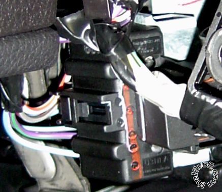
Guess I have to get some diodes. Here are a few more installation pics. This is the 5901 and the Fortin module mounted on a bar that runs along the bottom of the dashboard, directly below the steering column. The Fortin is attached to the Viper with Velcro. 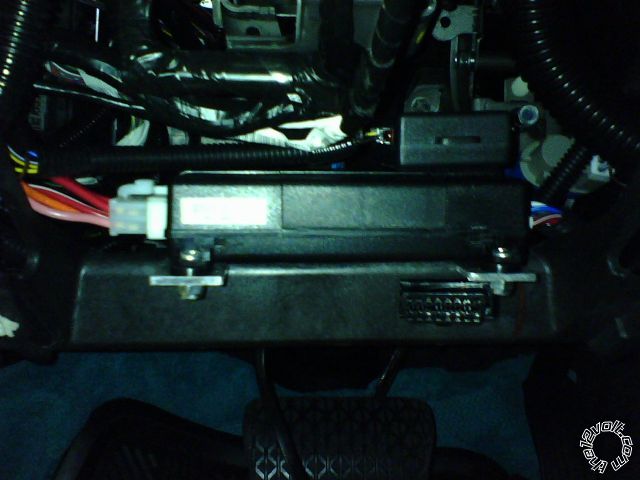 This is the trunk pop connection at the dash switch. 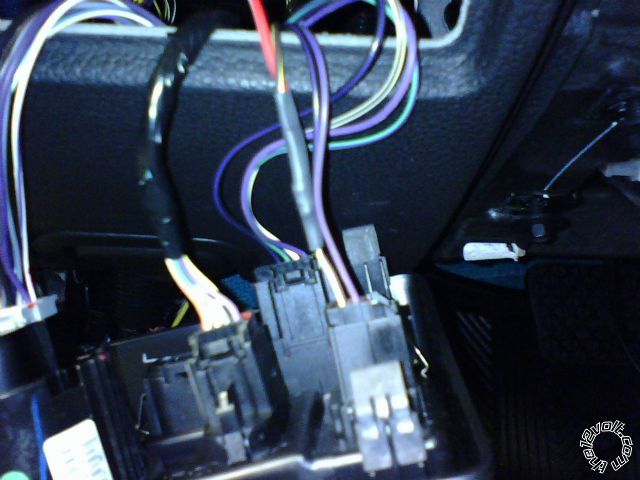 This is the horn connection at the steering column. Its the bottom wire blue/white. You can see the heat shrink sticking out past the tape. 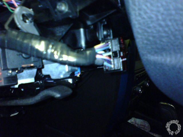 -------------
Posted By: monty862
Date Posted: February 17, 2010 at 1:55 AM
My buddy says he has some 3 amp diodes. Can I use them or should I get the 1 amp?
-------------
Posted By: tedmond
Date Posted: February 17, 2010 at 6:59 AM
3 amp will work fine as well. ------------- Ted
2nd Year Tier 1 Medical School
Still installing as a hobby...pays for groceries
Compustar Expert
Posted By: tedmond
Date Posted: February 17, 2010 at 6:59 AM
btw very clean installation ! looks good. ------------- Ted
2nd Year Tier 1 Medical School
Still installing as a hobby...pays for groceries
Compustar Expert
Posted By: monty862
Date Posted: February 18, 2010 at 12:57 AM
Thanks. It should though, I've routed and re-routed trying to get the cleanest look and least clutter. I'm attempting to make it hard to tell it is even installed unless you really look for it. Still studying on the antenna location. Anyway, I went ahead and got the 1 amp diodes for the door triggers. I've been prepping them tonight. Here they are. I left the heat shrink off one for the photo. I used some cut wire from shortened leads off the H1 harness. The GREEN wire from the H1 harness will attach to the other end of the diodes. Am I correct in thinking that if I attach additional sensors (tilt,glass breakage,external shock) to the blue H1 trunk/instant trigger wire, that all those must be individually isolated as well? Thanks again. 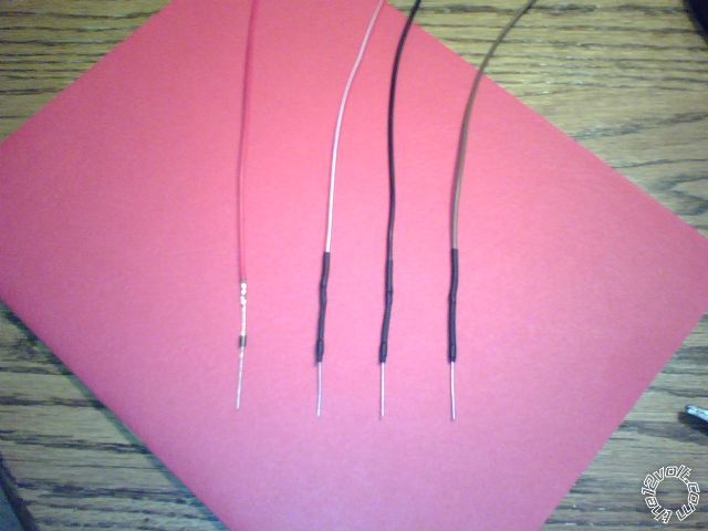 -------------
Posted By: tedmond
Date Posted: February 18, 2010 at 7:07 AM
just a tip, you might find it easier if you have a piece of wire comming off the other end as well.
I dont know if you are soldering the diode to the wire on the van or the wire part goes to the van, WHen you have wire branching off the diode from both ends, it makes it easier for a more clean/factory look. when adding additional sensors, you will need to isolate them. I am not too familiar with the new DEI brains, but from what i remember the shock sensor is built in, andif addition sensors want to be added, its simply plug into the existing socket on the brain. also, i would like to thank you for being patient and taking this install on to learn something, and you actaully READ what we got to say. Had my fair share of stubborn people. Cheers
------------- Ted
2nd Year Tier 1 Medical School
Still installing as a hobby...pays for groceries
Compustar Expert
Posted By: monty862
Date Posted: February 18, 2010 at 8:09 AM
That's one of the great things about these forums, you get the input of so many people. If you get an opposing opinion on something then you have a chance to see it from another perspective. I appreciate you and everyone taking the time to read and post what they think is the best or correct answer. As for the diodes, the wired side is going to the smart junction box. It is a pain in the a** to get at. After I see how long I need the leads from the diodes to be, then I'll solder the other end on before attaching to the SJB wires. I was going to bring these diodes down to the kick panel area in case they ever fail. Don't want to have to get back to this SJB again. I was hoping to avoid going to the SJB altogether, but it is the only place my install sheet lists for location of the door trigger wires. I asked on an earlier post if I could connect my parking lights at the headlight switch, but they didn't recommend it. Since I have to go to the SJB for the door triggers, it's not that much more bother. On the subject of the 5901, it has a single "mux" input for an add-on sensor. I plan on using it for a proximity (radar) sensor. I believe for additional instant trigger inputs you are suppose to use the blue H1 trunk trigger wire. I also purchased a tilt and external shock sensor in case the internal sensor wasn't sensitive enough. Hopefully I won't need the external sensor. Thanks again! -------------
Posted By: monty862
Date Posted: February 25, 2010 at 6:42 AM
I got my door triggers wired up. My install sheet stated (N.C. negative). I installed the diodes with the bands towards the SJB. Connected the other ends to the green H1/8 wire. When testing the alarm, I get no response when I open any door. The message center on the car is still functioning properly and will tell which door is open. I found a conflicting install sheet from Installogy that stated (N.O. negative). I changed the setting on the 5901 to N.O. and then when arming it reports door open when they are not. Any ideas on where I went wrong? Thanks
-------------
Posted By: monty862
Date Posted: February 25, 2010 at 12:02 PM
I tested each lead after I attached them to the door trigger wires. The DMM showed a limited continuity reading to ground when the door was closed, and no reaction when the door was open. Thought this sounded right. Trunk trigger works fine. So does the hood trigger. Anyone see this before? Thanks -------------
Posted By: monty862
Date Posted: February 26, 2010 at 8:01 AM
I found this possible solution online. Do you think it applies to my situation? "The small pulse is not strong enough to trigger the alarm. Diode isolate each door trigger and wire to a relay. When the door opens it will trigger the relay and send a ground to the alarm. How to? Combine all diode isolated trigger wires and connect that wire to pin 85 and 12V to pin 86. Then pin 87 to ground and pin 30 to the alarm." Thanks
-------------
Posted By: monty862
Date Posted: February 27, 2010 at 3:35 PM
This didn't work. Any suggestions appreciated.
-------------
Posted By: monty862
Date Posted: March 14, 2010 at 5:27 AM
Update on 2010 Fusion door triggers. It looks like a module called a DTIMAZDA (Door Trigger Interface- Mazda, because I guess it was the first automaker to need it) is required. It changes the system from a Negative Normally Closed, to Positive Normally Open. It has 10 connections that are required. You cut all four of the cars door trigger wires. Four of the DTIMAZDA wires go to one side of the cut wires and four go to the other side of the cut wires. One goes to 12 volts and the last to the positive door trigger wire on the 5901. Once this was installed and the settings on the 5901 were adjusted the alarm functions properly. Thanks to Howie for the info. More install pics soon.
-------------
Posted By: monty862
Date Posted: March 18, 2010 at 8:06 AM
Here are a couple of more installation pics. The majority of the alarm connections can be made from the headlight / message center / trunk pop/ switch pod. The two connectors shown unplug from the smart junction box and all their wires will extend out through the switch pod location. The small 26 pin connector (c) has the four door triggers, trunk trigger, trunk pop, power locks, parking brake and hood pin. Talk about convenient. It also lists, trunk alarm shunt. Not sure what that does, I'll have to ask Howie. The larger connector (d) has the parking lights. 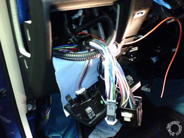 Here is the field disturbance sensor. I was able to mount it in the console under the storage bin. This rectangular cut out in the bottom of the bin, under the liner, allows access to adjustment screws. 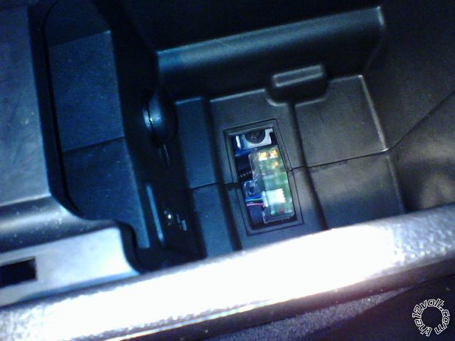 -------------
Posted By: monty862
Date Posted: March 21, 2010 at 9:44 PM
New problem. I guess it's not really new, just didn't think about it till now. I have a tilt sensor and a glass breakage sensor. I diode isolated them and tapped into the trunk trigger (blue H1/7 wire). Problem: the trunk trigger is the same system as the door triggers. Neg. Norm Closed. Trunk trigger worked fine by itself, but alarm won't go off for these two new sensors. the DTIMAZDA fixed my door trigger problem. I'm thinking if I get another DTIMAZDA module and use two of the four inputs on the trigger side of the module for the sensors and not use the outputs (not needed) on the DTIMAZDA, that should work. Does this sound correct? Thanks
-------------
Posted By: monty862
Date Posted: March 21, 2010 at 9:54 PM
After I thought about it some more, I think I'll have to use one ot the DTIMAZDA trigger inputs for the trunk trigger. And the corresponding DTIMAZDA output to the SJB. Correct?
-------------
Posted By: monty862
Date Posted: March 21, 2010 at 10:33 PM
Or, could I use the viper normally open hood pin?
-------------
Posted By: monty862
Date Posted: March 22, 2010 at 12:58 AM
Would it be possible to use BOTH the + pos violet H1/6 and the - neg green H1/8 door trigger inputs? They would be used for different things. I'm using a DTIMAZDA module on my 2010 Fusion door triggers which requires me to use the + pos violet H1/6 wire from the Viper. I want to add a tilt and glass sensor. Normally you'd tap into the trunk trigger wire to add these sensors.. My trunk trigger is the same set up as the doors (- Neg Norm Closed.) This gives me the same dilemma as the doors did. Even though you open one circuit (trunk, or tilt, or glass) the system still gets a ground from one of the others and no alarm is sounded. I guess I could use another DTIMAZDA module. But, if I can use the - neg green H1/8 wire, I can tap the tilt and glass sensor into that for my alarm input. The only drawback I see is the two way remote would probably show door trigger for the tilt and glass report. But it would have shown trunk trigger if wired normaly. Has anyone tried this before or know if it will or won't work?
-------------
Posted By: monty862
Date Posted: March 29, 2010 at 1:17 AM
If I could, I'd delete my last four posts. The simple solution for this, was to tap into the MUX port connection. I cut the blue alarm wire that goes to the MUX port from my proximity sensor. I put a diode on this cut wire with the band facing the proximity sensor. I also put a diode on the wire from the tilt sensor with the band facing the sensor. And a diode on the wire from the glass breakage sensor facing the sensor. Soldered all three dioded wires (prox, tilt, glass) to the blue wire I cut coming from the MUX connector.All sensors are now working properly. I also cut the black wire from the proximity sensor and ran it to the ground when armed wire. Now the proximity sensor only activates when the alarm is armed. The ground wire from the MUX connector is a constant ground and the proximity sensor was staying on whether the alarm was armed or not. All I have left to do is hook up the defroster wire and mount the antenna. I'd like to hook up the heated seats too, but I'm not too sure how to do that. -------------
Posted By: monty862
Date Posted: April 11, 2010 at 2:31 AM
I have a PDF of the center console removal guide for 2010 Fusion / Milan. Can't post it due to copyright. Be glad to send it to anyone who needs it. I also have a link to a Nav / Climate / Radio bezel removal video.
-------------
Posted By: monty862
Date Posted: April 19, 2010 at 5:52 AM
Fly in the ointment. Of course. Rear defroster latch; heated seats pulse. I wanted both to turn on automatically with the status wire. I guess I'll use the status wire for the defroster. It has a 10 minute time limit. The Fusion also has a timer on the defroster, but I'm not sure of the length. The seats have no timer. I'll use auxillary 1 for the heated seats and turn them on manually instead.
-------------
Posted By: monty862
Date Posted: April 23, 2010 at 1:59 AM
Rear defroster and heated seats wired up and working properly. The climate control module is located behind the Navagation screen, on cars so equipped. This is where you will find the 26 pin plug (A) to wire the seats and defroster. I would imagine it is located in the same place on non-navagation units. Again the seats are pulsed and the defroster latched. Almost done! 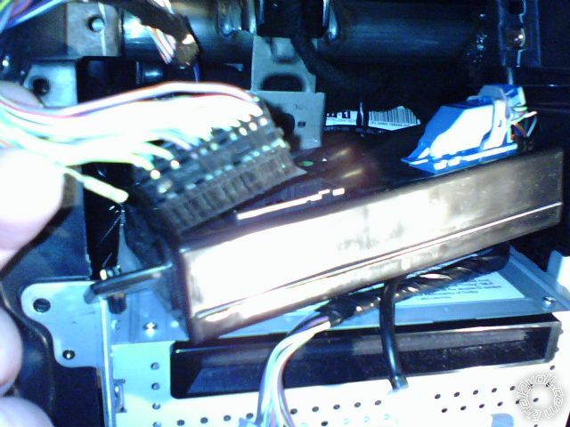 -------------
Posted By: monty862
Date Posted: April 30, 2010 at 12:47 AM
Here are some pics of where I installed two relays for the defroster and heated seats. I also have the DTIMAZDA module mounted here. Easily accessible through the side opening on the dashboard. 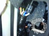   Foam wrapped over relays to prevent rattle. Sorry pics so small, used phone camera. -------------
Posted By: monty862
Date Posted: May 10, 2010 at 8:05 AM
I finished up the install last night. Only took 4 months! LOL. I'm pleased with the results and I'm glad I did it myself. Thanks to all the great guys that posted and helped me out. If you are installing in a 2010 Fusion here is a quick summary. Viper 5901 - DEI DTIMAZDA Module - Two Relays and Sockets - These are what I needed to install my unit. You can get by without the DTIMAZDA if you use the domelight circuit for your door trigger. Relays were for the seats and defroster connections. Remove the access panel on the side of the dashboard (drivers side), the headlight switch / info cluster pod, (these two are more easily removed by putting your hand under the dash and relasing the tabs with your finger), Dash panel below steering column (pops off) and lower steering column cover (two Philips, one Torx screw). Removing these four covers should give you access to nearly everything you need. The seats and defroster require you to remove the center dash facia around the radio / Nav unit. You do not need to remove the drivers kick panel. Disconnecting battery didn't cause me any problems on my Sport model. Glad to answer any questions about this install. I might try to add window and sunroof modules down the road. I also might post a video on you tube later. So, thanks again to everyone for your help!
-------------
|