I am having trouble with the wiring for the viper 211hv system. I am installing the system in a 1988 ford mustang with factory power locks. I have done the following wiring so far. I have connected the pink / YELLOW and pink/lt green wires coming from the passenger side to the H1/6 and H1/17 respectively. (note: the passenger side is the master or where the 12v signal comes from) I then connected the drivers side pink / YELLOW and pink/lt green to the H1/5 and H1/8 respectively. I wanted to know what I do with the fused H1/7 & H1/9 combined wire and how to get the key fob to work?
The door switches on both sides function in both the lock and unlock positions. The module also clicks and flashes the LED when pressing the lock button. It also clicks when pressing the unlock feature and stops the led flash.
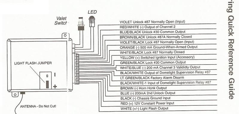
H1/1 Red - Yellow constant +12V
H1/5 GREEN/ Black - pink / YELLOW
H1/6 WHITE/ Black - pink / YELLOW
H1/8 Blue/Black - Pink/ light green
H1/17 BROWN / black - Pink/light Green
H1/11 Black - chassis ground
H1/15 Yellow - RED / Light Green Switched +12v
Viper 211HV primary harness (H1, 12-pin connector
 1988-89 Ford Mustang Alarm, Remote Starter, Keyless Entry Wiring Information
Constant 12V+ Yellow Ignition Switch Harness
Starter WHITE/ Pink Ignition Switch Harness
Ignition RED / Light Green Ignition Switch Harness
Accessory Gray / YELLOW Ignition Switch Harness
Tach Dark GREEN/ YELLOW Coil
Neutral Safety Wire Not Grounding OEM Switch opens Starter Circuit
Brake Switch RED / Green Brake Switch
Trunk Release Purple / YELLOW (+) Switch in Dash
Trunk Pin n/a Works with Dome Light
Parking Lights Brown Light Switch
Head Lamp RED / Yellow (+) Light Switch
Hood Pin n/a
Factory Disarm n/a
Door Trigger BLACK/ Light Blue Pin Switch or Courtesy Light
Door Lock Pink / YELLOW Driver's Kick Panel or behind left Front Speaker
Door Unlock Pink/Light Green Reverse Polarity
Horn Wire Yellow/Light Green (-) Steering Column
Windows Up LF=Yellow, RF=Yellow/Black, LR=Yellow/Light Blue, RR=Yellow/Black
Windows Down LF=WHITE/ Black, RF=RED / Black, LR=RED / Light Blue, RR=RED / Black
1988-89 Ford Mustang Alarm, Remote Starter, Keyless Entry Wiring InformationThis seems hopeless. I have tried wiring the module as per the instructions and still nothing. The most common wiring solution I could find is this:
"WHITE/ black to lock switch
GREEN/ black to lock motor
BROWN / black to unlock switch
blue/black to unlock motor
and purple to whatever trigger you need (12v for positive trigger, ground for negative trigger)"
I can't get it to work in any configuration. I have also tried to wire it per the bulldog instructions which are nearly identical to the viper instructions. When I connect the fused purple and PURPLE / black wires to ground it does nothing, when I connect said wires to a +12v source it pops the fuse. It doesn't matter how the lock and unlock wires are connected either, I can reverse them and it does the same thing. So what i have right now are working door lock switches and a keyfob that makes the viper module click.

Did you ever get this figured out? I am doing the same install on my '88 too. I've been trying to make heads and tails of this setup, right as I was starting to dig in I finally realized that the 211hv has built in relays. That sure changed things, should have read the instructions a bit closer.
Anyway, I can't really give much advice as I was hoping this thread would be answered. However, I want to throw some things out for thought. I believe the Mustang does not have separate lock wires for the left and right side. So basically you can just wire up the driver side and it will control the passenger side too. I wonder if that might be a cause for some of your problems.
My understanding of the wiring is the same as you put in your previous post.
BROWN / Black to switch side of Pink/Light Green
Blue/Black to actuator side of Pink/Light Green
WHITE/ Black to switch side of Pink / YELLOW
GREEN/ Black to actuator side of Pink / YELLOW
Violet, Violet/Black to either +12v or ground. I am guessing for the Mustang it is for +12v but I honestly have no clue.
I am trying to figure out if there is a typo in the installation guide. The WHITE/ Black and Violet/Black are both supposed to be wired to 87, shouldn't the WHITE/ Black be 87A? Those are just some of my thoughts and questions, hopefully someone might chime in soon. I am getting very eager to get this thing installed.
Have any of you tested to verify that you do indeed have the actuator motor wires and what polarity they rest at? It's farly simple once you have discerned the type of locking system in the vehicle! I will see if i can locate a diagram to assist!
-------------
This diagram verifies you do indeed have reverse polarity locking, it's simple here's what you do, You have to cut both motor wires in half should be easily located at the switch, when you have cut them wire like this
On the unlock wire connect the side that comes from the switch to the BROWN / black, and the side that leads into the car to the blue/black!
On the lock wire connect the side from the switch to the WHITE/ black and the side from the car to the GREEN/ black!
Assuming here that this system rests at ground the fused violet and violet/black will connect to a good twelve volt source at least fifteen amps capable! Of course verify first what it does rest at with a meter! I've only seen a rest at twelve once in a vintage toyota!
-------------
Thanks for your reply! When I tested the wires they were 0 at rest. When pushing lock, the Pink / YELLOW reads 12v and the same for Pink/Lt Green when pressing the unlock.
Thanks t&t! Hopefully I can get it wired up tomorrow.
Muhaha, it's alive! Well....sort of. If I wire it as posted above, pressing the lock button unlocks it and the unlock button locks and arms it. I had to reverse the wiring to:
BROWN / Black to switch side of Pink / YELLOW
Blue/Black to actuator side of Pink / YELLOW
WHITE/ Black to switch side of Pink/Light Green
GREEN/ Black to actuator side of Pink/Light Green
Anyone know how difficult it would be to get the progressive locking to work when the locks don't have separate left and right wires? Thanks again for your help, I'm off to figure out how to wire the lights to flash.