viper 5101 8 pin connector
Printed From: the12volt.com
Forum Name: Car Security and Convenience
Forum Discription: Car Alarms, Keyless Entries, Remote Starters, Immobilizer Bypasses, Sensors, Door Locks, Window Modules, Heated Mirrors, Heated Seats, etc.
URL: https://www.the12volt.com/installbay/forum_posts.asp?tid=119777
Printed Date: May 02, 2026 at 10:21 PM
Topic: viper 5101 8 pin connector
Posted By: shafferny
Subject: viper 5101 8 pin connector
Date Posted: January 31, 2010 at 6:50 AM
I just purchase a Viper 5101 to go into my 2003 Jeep Liberty. The installation manual is a bit vague when it comes to the H3 connector, or "Heavy guage, 8-pin connector". Can anybody tell me what the characteristics of the wires I need to connect these to are? For example:
|
H3/1 |
PINK |
IGNITION 1 INPUT/OUTPUT | Needs to be connected to a constant 12v in the ignition harness. TIA, Chris Without the garble. ;-)
Replies:
Posted By: shafferny
Date Posted: January 31, 2010 at 11:43 AM
When I installed previous remote starters made by Design Tech, the instructions would give directions such as....
4. Blue Wire (14 AWG) Ignition 1
Connect the BLUE wire to the ignition 1 wire of your vehicle. This wire will measure +12 Volts on the test meter in the run and start position, and is off in the lock/ off and accessory positions It made find the correct wires accurate and easy. I emailed DEI and the website I purchase the remote car starter to see if I could get a vehicle specific wiring diagram, but I'm not sure if I'll get a satisfactory response. As most of you know, DEI's website is useless to the DIY installer. It's geared soley for the end user and professional installer/authorized dealer.
.
Posted By: tedmond
Date Posted: January 31, 2010 at 11:50 AM
connect that pink H3/1 to RED / BLUE (+) @ ignition harness.
-------------
Ted
2nd Year Tier 1 Medical School
Still installing as a hobby...pays for groceries
Compustar Expert
Posted By: t&t tech
Date Posted: January 31, 2010 at 1:01 PM
To expand on ted's post Green- starter wire (key side) Purple- starter wire (engine side) orange - acesory pink/white second ignition all the reds to 12volts constant -------------
Posted By: shafferny
Date Posted: January 31, 2010 at 1:12 PM
Is this correct for the H3 harness? H3/1(Pink) ->RED / Blue @ Ignition Harness H3/2(RED / White) ->N/A H3/3(Orange) ->BLACK/ Orange @ Ignition Harness H3/4(Violet) ->Yellow @ Ignition Harness H3/5(Red) ->Unsure (Red & Pink/Black @ Ignition Harness)?? H3/6(Pink/White) ->N/A H3/7(Pink/Black) ->N/A H3/8 ->Unsure (possibly BLACK/ White @ Ignition Harness)??
Posted By: shafferny
Date Posted: January 31, 2010 at 2:49 PM
I appoligize if I'm being ignorante here, but I don't see a green wire at all in the harness. Page 24 of the PDF below are the wires I'm trying to figure out. The instuctions aren't clear at all. https://www.directeddealers.com/manuals/IG/Viper/N4102V_2008_09_web.pdf Here are is the vehicle wiring chart I received from Direct back in 2007 when I installed the current remote car starter. 
Posted By: t&t tech
Date Posted: January 31, 2010 at 2:59 PM
That unit may not have the starter kill/anti grind then, Ignore the green wire then, connect the purple to the yellow! RED / white and red go to pink/black in the ignition harness! -------------
Posted By: shafferny
Date Posted: January 31, 2010 at 3:21 PM
The anti-grind feature is optional.
H3/1(Pink) ->RED / Blue @ Ignition Harness H3/2(RED / White) ->(Red & Pink/Black @ Ignition Harness) H3/3(Orange) ->BLACK/ Orange @ Ignition Harness H3/4(Violet) ->Yellow @ Ignition Harness H3/5(Red) ->N/A H3/6(Pink/White) ->N/A H3/7(Pink/Black) ->N/A H3/8 ->Unsure (possibly BLACK/ White @ Ignition Harness)??
Posted By: shafferny
Date Posted: February 01, 2010 at 5:06 PM
Can anybody confirm this? I contacted the retailer I purchased the remote starter from, Dealer Cost Car Audio, and they wouldn't provide me with any information because they didn't want to be held liable for anything. This is frustrating to say the least.
Posted By: t&t tech
Date Posted: February 01, 2010 at 5:51 PM
All is correct above, except the red h3/5 connects with the RED / white at either of the twelve volt constant wires at the harness! What colour is your h3/8 wire?
-------------
Posted By: shafferny
Date Posted: February 02, 2010 at 5:09 PM
Okay. From all the Googling I've done, this is what I've found. All the red wires go to +12v consant just as you said t&t tech! My connections should be as follows... H3/1(Pink) ->RED / Blue @ Ignition Harness (+12v in the "run" and "start" position - typical ignition 1 wire) H3/2(RED / White) ->N/A (+12v constant - polarity feed for the ignition 2/flex relay.) H3/3(Orange) ->BLACK/ Orange @ Ignition Harness (+12v Accessory Output ) H3/4(Violet) ->Yellow @ Ignition Harness (+12v Stater Output/"Crank" wire) H3/5(Red) ->(+12v constant- polarity feed for the Ignition 1 relay) H3/6(Pink/White) ->N/A (Ignition 2/flex relay output) H3/7(Pink/Black) ->N/A (flex relay input) H3/8 (RED / Black)->(+12v constant - polarity feed to the accessory and starter relays) I don't think I need the H3/2 since it is only the polarity feed for the ignition 2/flex relay. I won't be using it. Assuming this is correct, would the Red & Pink/Black in the ignition harness be sufficient in size to power all the red since they are only polarity wires, or would I be safer off running a dedicated wire to power these three? BTW, I'm not impressed with DEI, nor the place I purchased the car starter from. Neither will offer documents or diagrams for fear of liability. I understand their reason, but if it that was the case no one would ever sell car parts. lol
Posted By: shafferny
Date Posted: February 02, 2010 at 5:12 PM
The weird thing is, all the other wires/connections in the manual are pretty well laid out and logical.
Posted By: t&t tech
Date Posted: February 02, 2010 at 6:04 PM
The power wires at the ignition harness will suffice, you will also need to power that h3/2 wire!
-------------
Posted By: shafferny
Date Posted: February 03, 2010 at 4:45 PM
Really? I was thinking the H3/2 would only be needed if the H3/6 was going to be utilized. Since my Jeep Liberty doesn't have a second ignition, accessory, or starter wire I didn't think I would be using it. I suppose it could be used for some other purpose as a "flex relay" if desired. H3/2 - (+) FUSED (30A) FUSED IGNITION 2 /FLEX RELAY INPUT 87 This wire is the polarity feed for the ignition 2/flex relay. H3/6 - IGNITION 2 / FLEX RELAY OUTPUT 30 This wire is factory programmed as Ignition 2 and can be programmed as a 2nd accessory or 2nd starter. Am I thinking correctly here?
Posted By: shafferny
Date Posted: February 05, 2010 at 2:54 PM
Anybody?
Posted By: moonliter
Date Posted: February 05, 2010 at 4:39 PM
According to the wiring chart on your own post, this jeep has 2 +12v sources, 1 ign, 1 starter & 2 acc's. therefore you're going to use all the inputs and outputs (except H3/7) on the H3 8-pin connector. You'll have to program the flex relay from default 2nd ign to 2nd accessory.. see the chart below 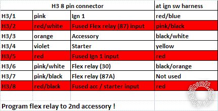
Posted By: shafferny
Date Posted: February 06, 2010 at 4:30 PM
You're absolutely right moonliter. I don't know why I didn't see that. Thanks for the clarification. I appreciate all the help I've recieved on this forum. Thank you!
Posted By: smokeman1
Date Posted: February 08, 2010 at 11:47 AM
guidance anyone, I am looking for the same type of help with the same heavy gauge H3 8 pin connector for a 2005 Ford Focus. As Shaffnery wrote, the instructions are vague as to what and where. I have a posting at viper 5301on 2005 ford focus on this site looking for the same help. On the 2005 focus wiring chart I have one 12 volt constant (red)(+), one starter (gray/black)(+), one ignition 1 (GREEN/ YELLOW(+), and one ACCESSORY /HEATER blower 1(yellow(+). No second 12 volt constant, starter, ignition, or accessory wires on the car. Thanks for looking
Posted By: shafferny
Date Posted: February 08, 2010 at 4:34 PM
Judging from the wiring diagram I got from DEI, it looks like the Red & Pink/Black wire(the 12v constant in the ignition harness) powers the ignition wire, both accessory wires, and the starter wires. I think I'm going to tap into that to power the H3/2, H3/5, and H3/8.
Posted By: shafferny
Date Posted: February 09, 2010 at 4:18 PM
After reading the topic below, I've decided to split up my power needs up like this.. . The +12v power wire for the primary harness(H1/2), will also be connected to Pink/Black in the ignition wire harness. I will use the red wire in the ignition harness to also power the Directed 457cw door lock interface I'm going to install(5amps at the most). Both the red and pink/black wires in the ignition harness are 12gauge wires with 40A fuses each. I think things will be sufficient this way. https://www.the12volt.com/installbay/forum_posts.asp?tid=85310&KW=tapping+ignition+wires
Posted By: moonliter
Date Posted: February 09, 2010 at 5:03 PM
If you want, you can pick up the dark.blue ( constant +12v ) also at the ignition harness for the (H1/2). Check your pm, I have more info if you need.
Posted By: shafferny
Date Posted: February 09, 2010 at 7:02 PM
I noticed from the vehicle's factory service manual there are three 12v constant wires supplied to the ignition switch, red, pink/back, and dark blue(all 40A fused and 12ga). The information I recieved from Directed Electronic didn't indicate the dark blue wire at all. I could perhaps used the dark blue wire to power the H1/2 and the door lock interface I'll be installing. My other thought is to use the pink/black for the H3/2, dark blue for the H3/5, and the red for the H3/8. Then run a dedicated power wire from the battery to power the H1/2 and door lock interface.
Posted By: moonliter
Date Posted: February 09, 2010 at 7:27 PM
I think you are way over your head. What I had suggested is more than enough. If you like, for sure you could use dark.blue to power the H1/2 & the power lock module.
Posted By: shafferny
Date Posted: February 10, 2010 at 7:54 AM
Every other remote starter I've installed in the past has had it's own power supply directly from the battery. This is the only time I've ever considered tapping into the ignition harness for power. We've all heard the horror storys of someone's car going up in flames due to a misinstalled system., so I'd rather error on the side of caution than take a chance comprimising things. That's why I'm trying to figure out the best way to install this without taking the chance of over loading things. On a different topic, yet related, I was looking at the installation manual for the remote car starter that I installed in my Jeep almost three years ago and it only has provisions for one accessory output. Interesting. Here is the manual from that remote car starter... https://www.designtech-intl.com/pdf/manuals/28624T.pdf As you can see, it's night and day between the Viper manual and Design Tech. The Design Tech manual is clearly geared towards the DIY installer.
Posted By: moonliter
Date Posted: February 10, 2010 at 6:36 PM
I already had mapped out all the wirings from the (H3) 8-pin harness to the appropriated wires at the ignition switch. What I had done, I mimic the function of each relay for the operation of the ign, starter,& accessories just like the jeep factory ignition would do. Regarding the H1/2, dark.blue at the ign harness will be fine for the module. shafferny wrote:
I could perhaps used the dark blue wire to power the H1/2 and the door lock interface I'll be installing. My other thought is to use the pink/black for the H3/2, dark blue for the H3/5, and the red for the H3/8. Then run a dedicated power wire from the battery to power the H1/2 and door lock interface.
Check this out & compare to the chart I posted, with the way it was setup I couldn't figure how you could overload the system. https://www.the12volt.com/installbay/file.asp?ID=831
Posted By: shafferny
Date Posted: February 12, 2010 at 3:09 PM
Looking at the factory wiring diagram you're 100% right. My mistake. I will wire everything up as you directed. Thanks for all the help. I appreciate it.
Posted By: shafferny
Date Posted: February 12, 2010 at 8:56 PM
I think what was throwing me off was that I was trying to think logically about the way things work. For example, I was thinking that if you have a heavy guage12v constant coming into the ignition switch, then you must have a heavy guage power wire coming out of it. It doesn't necessarily work that way though. In fact, from looking at the diagram the red wire powers both the BLACK/ white and RED / dark blue at the same time, eventhough the BLACK/ white and RED / dark blue are the same size wire as the red. One would think that this would overload the red wire, but that's not the case. moonliter, the diagram you posted is much better than the factory service manual I have. It's not as convoluted. The factory service manual is much more detail, and therefore you have to jump from page, to page, to page, making it difficult to see the big picture. Thank you.
Posted By: shafferny
Date Posted: February 16, 2010 at 5:36 PM
Got it all installed. Everything works great. I had to repair a couple of the ignition harness wires where the previous remote starter was soldered in, but no biggie. Thanks for all the help.
Posted By: shafferny
Date Posted: February 17, 2010 at 8:45 PM
To answer my original question, and to possible help anybody else out. This is the way I understand the H3 harness on the Viper 5101. Someone please correct me if I'm wrong.
|
H3/1 |
PINK |
IGNITION 1 INPUT/OUTPUT | This wire gets connected to the wire in the ignition harness that shows 12volts in both the "start" and "run" position.
|
H3/2 |
RED / WHITE |
(+) FUSED (30A) FUSED IGNITION 2 /FLEX RELAY INPUT 87 | This is the "input" for the flex relay. If needed, you will supply this wire with 12 volts constant. Basically the flex relay is just a relay that can be programed to function, or "behave" if you will, in one of three ways. It can be programmed to be used as a second starter wire, a second accessory wire, or a second ignition wire. For example, if you're vehicle has two accessory wires that are normally powered up when your vehicle is running, then you'll need program the remote start module to make the flex relay behave as an accessory. By default it's programmed as a second ignition wire. This wire has other uses if you want to get creative.
|
H3/3 |
ORANGE |
ACCESSORY OUTPUT | This wire gets connected to the wire in the ignition harness that shows 12volts in the accessory and run positions.
|
H3/4 |
VIOLET |
STARTER OUTPUT | This wire gets connected to the starter wire in the ignition harness. The starter wire shows 12volts in the start position only.
|
H3/5 |
RED |
(+) FUSED (30A) IGNITION 1 INPUT | This wire gets connected to 12volts constant. It supplies power for the H3/1 (PINK) wire when the vehicle is running via remote start.
|
H3/6 |
PINK/WHITE |
IGNITION 2 / FLEX RELAY OUTPUT 30 | This wire gets connected to your second ignition, second accessory, or second starter wire in the igntion harness, whichever you're going to program it for.
|
H3/7 |
PINK/BLACK |
FLEX RELAY INPUT 87A key side (if required) of FLEX RELAY | This wire is used when you need to isolate the ignition switch during the remote start operation. As i understand it, when you start your vehicle with the key, power flows from the ignition switch through the H3/7(Pink/Black) and out the H3/6(Pink/White). Since the flex relay is at rest, contact 87a transfers power to contact 30 of the flex relay. When the vehicle is started with the remote starter then power from the H3/2(RED / White) puts power through to the H3/6(Pink/White).
|
H3/8 |
RED / BLACK |
(+) FUSED (30A) ACCESSORY/STARTER INPUT | This wire should be connected to 12volts constant to power. It supplies the power for the H3/3(Accessory) and H3/4(Starter Output) wires.
Posted By: dfitzg
Date Posted: May 25, 2010 at 4:15 PM
is the H3/4 wire supposed to show 12 volts at all times ?
Posted By: t&t tech
Date Posted: May 25, 2010 at 4:31 PM
dfitzg wrote:
is the H3/4 wire supposed to show 12 volts at all times ?
NOPE! -------------
Posted By: dfitzg
Date Posted: May 25, 2010 at 5:25 PM
Can you look at a 95 240sx diagram and tell me which connections on this harness go to my ignition harness..
Posted By: blanx218
Date Posted: May 25, 2010 at 11:40 PM
the red, RED / white, & RED / black will need to go to the white +12V constant. (use a dmm to verify. there are 2 whites in the ignition harness and only 1 is constant +12V). the pink would go to BLACK/ red IGN1. pink/white goes to the car side of the white accessory wire. pink/black goes to the key side of the white accessory wire. orange wont be used. purple goes to the BLACK / YELLOW starter1. then program feature 8 in menu 3 to be 2nd accessory you will also need to wire up a relay for a 2nd starter wire. wire the relay as follows: pin85 and 87 to +12V constant pin 86 to purple in small 5pin harness pin 30 to BLACK/ white starter2 in the ignition harness
Posted By: catback
Date Posted: May 27, 2010 at 10:23 PM
shafferny wrote:
To answer my original question, and to possible help anybody else out. This is the way I understand the H3 harness on the Viper 5101. Someone please correct me if I'm wrong.
By god we'll make a professional installer out of you yet 
|