Before I get any hassle, let me give a little background.
I am a Electrical Engineering Technology student at Purdue University. I am doing a senior design project to control my winch for my jeep from my iphone. One of the features is to remote start the car when the battery voltage is too low. I cannot just buy a module for remote start, that defeats the purpose of my senior DESIGN project.
I found a schematic for a relay remote start
Here. The wiring for my vehicle is
Here. The part I am unsure of is that the relay diagram has 2 accessory wires and only one ignition wire. The wiring of my jeep has 2 ignition wires and only 1 accessory wire. I don't know enough about remote start systems and the wiring of my jeep to mess around with it.
I would appreciate any and all help.
Thanks
https://www.the12volt.com/installbay/forum_posts.asp~TID~119967~PN~2
link above was a remote start using 4 relays.
if you need additional ignition circuits, they can be simply wired in by using the existing trigger.
with an extra relay
85 - ground or switched ground source if available.
86 - ignition output from relay
87 - constant 12v
30 - to secondary ignition wire.
fuse everything accordingly.
-------------
Ted
2nd Year Tier 1 Medical School
Still installing as a hobby...pays for groceries
Compustar Expert
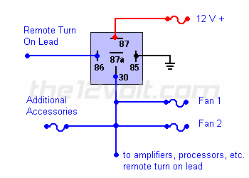
Heres a diagram of adding additional relays to a circuit...Instead of remote lead it would be ignition... Same as tedmond said...just a visual...
 Connecting Additional Devices to the Remote Turn On Wire () Connecting Additional Devices to the Remote Turn On Wire () |
Using a 30 amp SPDT relay, connect terminal #87 to constant 12 volts positive with a fuse rated to the sum of the additional accessories you've added and the components you need to turn on. (If you have two fans rated at 5 amps each and a neon light rated at 10 amps, you would use a 20 amp fuse plus 200 ma for each amplifier and processor.) Connect terminal #85 to ground, terminal #86 to the remote turn on wire from the head unit, and terminal #30 to each accessory with an appropriate fuse. A fuse (not shown) could also be used between the output of the relay (#30) and the remote turn on wire of the amplifiers and/or processors for extra precaution.
 |
-------------
M.E.C.P & First-Class
Go slow and drink lots of water...Procrastinators' Unite...Tomorrow!
