door actuator wiring
Printed From: the12volt.com
Forum Name: Car Security and Convenience
Forum Discription: Car Alarms, Keyless Entries, Remote Starters, Immobilizer Bypasses, Sensors, Door Locks, Window Modules, Heated Mirrors, Heated Seats, etc.
URL: https://www.the12volt.com/installbay/forum_posts.asp?tid=120319
Printed Date: May 04, 2026 at 1:33 AM
Topic: door actuator wiring
Posted By: frexe
Subject: door actuator wiring
Date Posted: February 22, 2010 at 8:32 PM
I am currently following the relay diagram.
With pin 30s to actuator
(2) pin 87A to ground
86,85,87,87 to 12v
85 and 86 to alarm brain
I have the 4 wires that need 12v soldered together and onto a 12gauge wire. And the two 87A grounds soldered together onto a 12 gauge wire.
But everytime I provide power and ground to those two connections my fuse blows out. I have burned out quite a few 15a and one 30a fuse(checking to see if the amps were the problem)
What is causing this short? Can I not merge the wires together like that?
Replies:
Posted By: frexe
Date Posted: February 22, 2010 at 8:38 PM
Hmm after drawing out a quick diagram in mspaint. My ground wires are like this. [ground]------------<======== is this my problem here? where the two grounds merge into one?
If so. Can I ground them in parallel to the same grounding point instead? Or do I need to split them up all together.
Posted By: frexe
Date Posted: February 22, 2010 at 9:24 PM
okay. I removed the ground loop. Wired them to separate grounds. Put in a brand new fuse. KABOOM. there goes another fuse. Thats fine because I collected way too many fuses from the junkyard.
But back to the question... why is it still shorting?
Posted By: tedmond
Date Posted: February 22, 2010 at 10:32 PM
are u sure the motor rests at ground? 85 - lock or unlock
86 - constant 12v
87 - constant 12v
87a - ground
30 - to lock or unlock wire
-------------
Ted
2nd Year Tier 1 Medical School
Still installing as a hobby...pays for groceries
Compustar Expert
Posted By: frexe
Date Posted: February 22, 2010 at 11:50 PM
its a two wire actuator. one for pos 1 neg.
Posted By: tedmond
Date Posted: February 23, 2010 at 6:30 AM
im aware that actuators are 2 wires, however there are 2 types of systems. 1) the motor rests at ground, and polarity changes on either wire to lock or unlock. (no switches or buttons)
2) 5 wire alternating, polairty is switched to lock or unlock, but the system rests at ground and has switches.
------------- Ted
2nd Year Tier 1 Medical School
Still installing as a hobby...pays for groceries
Compustar Expert
Posted By: sneakycyber
Date Posted: February 23, 2010 at 8:15 AM
If you can provide a model number of the actuators we can look them up.
-------------
Posted By: howie ll
Date Posted: February 23, 2010 at 12:52 PM
In the first post the relays were wired completely the wrong way round, look at Tedmund's correct posting.
By the way Tedmund, I did that mirror fold, 4 mini relays!
P.S. You're better off using the proprietary relays that come with these kits, then just use neg. pulsed outputs from your alarm.
Posted By: frexe
Date Posted: February 23, 2010 at 1:07 PM
I think the actuators are reverse polarity? I tested with a 9v battery. with the battery connected one way the actuator locks, and with the 9v flipped the actuator unlocks.
I am using the compustar cm6200 brain and it sends a (-) for lock and unlock.
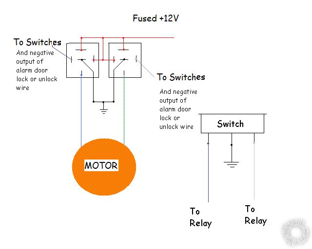
Its the "gunstyle" actuator in this link https://www.miata.net/garage/pwrlock.htm
I followed that relay diagram at the bottom.
Posted By: i am an idiot
Date Posted: February 23, 2010 at 1:20 PM
The diagram at the bottom of the page you mentioned is exactly what you need.
Posted By: frexe
Date Posted: February 23, 2010 at 1:40 PM
I have the relays wired up exactly like the diagram. But the fuse blows every time.
Posted By: moonliter
Date Posted: February 23, 2010 at 2:00 PM
Why dont you disconnect the actuators & try. If the fuse blows again, then definitely you had the relays wired wrong. Possibly you got the 30's & 87's mixed up. If they are good then check your actuators, make sure they are not stuck.
Posted By: t&t tech
Date Posted: February 23, 2010 at 3:00 PM
Even if the actuators are stuck this shouldn't cause the fuse to pop! Do as moonliter said and disconnect the actuators from the relays, however disconnect it at the relay and not at the motor, since it maybe a case of one of the motor wires shorted to the body through the door boot rubber! Notice the key word MAYBE!
-------------
Posted By: howie ll
Date Posted: February 23, 2010 at 4:25 PM
All actuators or motors or solenoids or simply door lock motors are reversing polarity. One leg sits on ground whilst the other side is pulsed pos.To reverse the motion the second side stays neg whilst the first side is pulsed pos. Yes I'm not counting pneumatic "pumps" as used on M/Benz and VAG cars.
Posted By: frexe
Date Posted: February 24, 2010 at 2:26 AM
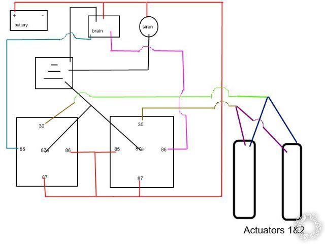
Okay I have drawn up my wiring.
Note:
-without the two actuator relays connected, the alarm and siren both work fine.
-with the relays connected the fuse shorts instantly.
-I have tried 30amp fuse.
-I have tried with the actuators disconnected.
-My relay wiring has been checked a million times.
My hypothesis is that there is some critical error in my diagram that you guys can easily spot. Hence the poor drawing.
Supplemental/irrelevant information
The brain is a cm6200 Remote start.
I have the Remote start working.
1991 mazda miata.
The 12v is drawn straight from the battery fused. (this is the fuse that keeps popping.
I have tested the relay for continuity. just testing pins 85 and 86 = no continuity. And just testing pins 85 and 86, they also have no continuity. So this should rule out that area of the relays I am supplying power?
Thanks for the help.
Posted By: howie ll
Date Posted: February 24, 2010 at 4:40 AM
Please do this, try it with one relay at a time or do the following:-
At rest 87a and 30 should be continuous. 30 and 87 aren't.
When the coil, 85 (-) and 86 (+) are connected, the circuit between 87a and 30 "breaks" and between 30 and 87 it "makes". 87a should NEVER connect to 87. Then still using your meter, still on continuity setting, join 1 lead to a good ground and the other lead to each motor wire in turn (with the motor wires disconnected). You should get no continuity. If you do that lead is shorting and that's your problem. If all of this fails, then please recheck your wiring, sorry, 35 years of experience tells me that if a fuse blows, something's in the wrong place! Last but not least you mentioned these relays were salvaged, nothing wrong there, the failure rate is one in millions. Had some 3 0r 4 fuel pump primer relays fail on Porsche and some Fords in the mid 90s but that was probably a Bosch or Hella batch problem, BUT check the connections, proprietary relays sometimes transpose 30 and 85, also make sure it's an 87a not 87b.
Posted By: i am an idiot
Date Posted: February 24, 2010 at 5:29 AM
As stated earlier, make sure you have the relays oriented properly. 30 is at the bottom of both relays in the above diagram. If you have the relays upside down, it WILL blow a fuse everytime you insert the fuse.
Posted By: jmkelly_us
Date Posted: February 24, 2010 at 2:52 PM
I am having the same problem. But it is not the 12+ fuse that is popping. It is the fuse coming out of the alarm. Any ideas why this would be happening. I have mine wired exactly the same way. I can get one part to work, either the unlock or lock, but the other will blow the fuse. The last questions is what amp fuse should be used for the relays?
Posted By: t&t tech
Date Posted: February 24, 2010 at 4:00 PM
jmkelly_us wrote:
I am having the same problem. But it is not the 12+ fuse that is popping. It is the fuse coming out of the alarm. Any ideas why this would be happening. I have mine wired exactly the same way. I can get one part to work, either the unlock or lock, but the other will blow the fuse. The last questions is what amp fuse should be used for the relays?
The amperage of the fuse will depend on the amount of solenoids in your circuit! Also you should start your own thread, as this may distract from assisting the OP! -------------
Posted By: frexe
Date Posted: February 24, 2010 at 6:10 PM
^quadruple check your wiring. If its correct...
What kind of output for lock and unlock does your alarm send out?
Ah I read somewhere that if the solenoid is seizing it may draw extra power and cause the fuse to blow. Check if that applies.
-------------
I got a giant DMM..but I haven't a clue how to use it
Posted By: i am an idiot
Date Posted: February 24, 2010 at 8:36 PM
This diagram is for add on actuators, if your vehicle has existing door locks, you may need to use a 5 wire setup. That diagram can be found in the relay section of this site.
Posted By: howie ll
Date Posted: February 25, 2010 at 11:08 AM
Ref the post on seized actuators. Installing 101, once installed make sure you can move the actuator by hand easily, and it should also move the lock rod freely when joined.
Posted By: frexe
Date Posted: February 25, 2010 at 1:03 PM
Problem solved.
Apparently one of my junkyard relays is one of those relays that have both 87s always connected T_T. There was no diagram on on this relay anywhere, but the ddm verified that the two 87 pins had continuity.
Thanks for the help everyone.
Now I only have one issue left. Back to my other thread.
-------------
I got a giant DMM..but I haven't a clue how to use it
|