reverse polarity without relay
Printed From: the12volt.com
Forum Name: Car Security and Convenience
Forum Discription: Car Alarms, Keyless Entries, Remote Starters, Immobilizer Bypasses, Sensors, Door Locks, Window Modules, Heated Mirrors, Heated Seats, etc.
URL: https://www.the12volt.com/installbay/forum_posts.asp?tid=120437
Printed Date: May 04, 2026 at 1:17 AM
Topic: reverse polarity without relay
Posted By: mad cow
Subject: reverse polarity without relay
Date Posted: March 01, 2010 at 5:59 PM
Is a relay the only way to reverse the polarity of a lock/unlock pulse? My alarm sends a negative pulse but my car needs a positive. I don't want to wire in 2 more relays because I've already had to wire in one for the parking lights and there are 2 more attached to the alarm harness, there just isn't that much room behind my glovebox for 5 more big relays. I've read that you can use transistors but I haven't found any concrete information.
Replies:
Posted By: KPierson
Date Posted: March 01, 2010 at 6:20 PM
If all you are trying to do is convert (-) to positive you can use a PNP transistor rated for at least 3A. You would only need two relays to convert (-) to (+). What kind of alarm do you have? You can also get smaller mini relays that don't take up near as much space. Another alternative would be a DEI 451M - two mini relays in one small enclosure designed to turn low current (-) pulses in to whatever you need them to be. ------------- Kevin Pierson
Posted By: oldspark
Date Posted: March 01, 2010 at 6:44 PM
2 relays? Not just one?
(And diodes for multiple inputs, or outs?)
Caveat - still no breakfast or coffee. I sense a bad D'oh! approaching... My brain's Safety Switch is overused... MCD - not RCD.
PS - the PNP is correct - my ROM must be working fine.
PPS - how come this OP Rookie (post #1!!) has taken my name?
Mr Idiot took someone elses. Now this!
(Dear Mad Cow - that's a joke.... I often refer to my mad cow disease (though it is really caused by too many hyper jumps). PPPS - Welcome!)
Posted By: mad cow
Date Posted: March 01, 2010 at 6:46 PM
How would you connect a PNP transistor to do that? A transistor is a much better idea because I probably have a few lying around so I won't have to buy anything extra. And I know I would only need 2 relays, but I already have 3 other ones so they'll all take up alot of space. I have a compustar CM4200DX, but I don't know if that helps.
Posted By: tommy...
Date Posted: March 01, 2010 at 6:51 PM
There are door lock coverters they sell...cheap...converts negative to positive...Usually have to cut the connector end of the polarity converters and then wire up door lock wires and a constant 12v source to the cut end...Here is a link to a similar one...(i can't remember the model #...Always say door lock thingy's when i order them...and same rep. for awhile) https://www.thefind.com/buy-2SyQsN7X0?result_view_id=1ac854c7537025252ce14adbc0e19c8e%3A0003&result_impression_id=1ac854c7537025252ce14adbc0e19c8e%3A0010&srcquery=door+lock+polarity+converters------------- M.E.C.P & First-Class
Go slow and drink lots of water...Procrastinators' Unite...Tomorrow!
Posted By: tommy...
Date Posted: March 01, 2010 at 7:21 PM
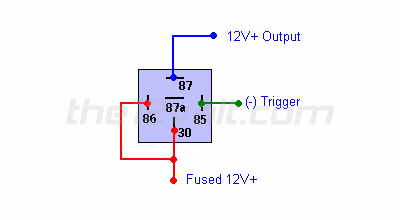
Here is the relay to convert...Would need one for each lock and unlock wire...You could also extend the wires and place the relays in another location...Really anywhere...Just extend the wires...
| Convert a Negative Output to a Positive Output |
If you have a switch or an alarm or keyless entry that has a negative output that you wish to use to switch a device that requires 12V+ such as a horn, dome light, parking lights, head lights, hatch release, etc., wire a relay as shown below to convert the negative output (trigger) to a positive output.
| ------------- M.E.C.P & First-Class
Go slow and drink lots of water...Procrastinators' Unite...Tomorrow!
Posted By: mad cow
Date Posted: March 01, 2010 at 7:35 PM
Again I don't want to use relays, I saw that diagram already. It'll also be too much of a hassle to run all those wires to somewhere else because I don't want to tear up the interior just to install an alarm.
Posted By: KPierson
Date Posted: March 01, 2010 at 8:32 PM
Run a 470 ohm resistor between the (-) out and the base of the PNP transistor.
Connect 12vdc to the emitter through a 22 ohm 1/4watt resistor. Connect the collector to your door lock wire. You must wire a diode between the (+) output of the transistor and ground to protect the transistor from the inductive relay coil. Seriously, grab a 451M and call it a day! ------------- Kevin Pierson
Posted By: mad cow
Date Posted: March 01, 2010 at 9:49 PM
KPierson wrote:
Run a 470 ohm resistor between the (-) out and the base of the PNP transistor.
Connect 12vdc to the emitter through a 22 ohm 1/4watt resistor. Connect the collector to your door lock wire.
You must wire a diode between the (+) output of the transistor and ground to protect the transistor from the inductive relay coil.
Seriously, grab a 451M and call it a day!
Where would I get a 451M? From what I've read it comes with some Viper systems, so is it safe to assume mobile audio/security stores will have them?
Posted By: tommy...
Date Posted: March 01, 2010 at 9:59 PM
mad cow wrote:
Again I don't want to use relays, I saw that diagram already. It'll also be too much of a hassle to run all those wires to somewhere else because I don't want to tear up the interior just to install an alarm.
Don"t see why you would have to tear up anything...Arent you going to have to give it 12v-ground-and run the wires to the doorlocks anyway...? I was just trying to add some ideas why the relays would work fine...In case you overlooked those options... But i posted a link for the converters...Cheap...easy to install...tiny...Or follow the others suggestion with the dei piece. ------------- M.E.C.P & First-Class
Go slow and drink lots of water...Procrastinators' Unite...Tomorrow!
Posted By: tommy...
Date Posted: March 01, 2010 at 10:00 PM
https://www.google.com/#hl=en&source=hp&q=451m+for+sale&rlz=1R2GPEA_en&aq=f&aqi=&aql=&oq=&fp=ed0664e20ac2de1f Google...wonderful thing...Possibly find it locally...Or similar...! Most shops would use relays,some use converters...Heck...the biggest shop close to me makes ALL of there bypasses with key.passlock,etc...I have seen these converters fail and send a constant signal to the door locks(key would'nt even turn in cylinder...doh)...Yet to see that with relays... ------------- M.E.C.P & First-Class
Go slow and drink lots of water...Procrastinators' Unite...Tomorrow!
Posted By: mad cow
Date Posted: March 01, 2010 at 10:06 PM
That doesn't help at all, I should have mentioned I'm looking for to buy locally.
Posted By: tommy...
Date Posted: March 01, 2010 at 10:08 PM
Call...Ask for door lock converters...! Crystal ball is malfunctioning at the moment...But if you put in where locally is...Maybe someone would have a suggestion...Otherwise...HOW the heck would we know if they sell it around you...? (sensing a bit of rudeness...ask myself...why post a question for help...then get mad...i dunno...)
-------------
M.E.C.P & First-Class
Go slow and drink lots of water...Procrastinators' Unite...Tomorrow!
Posted By: mad cow
Date Posted: March 01, 2010 at 10:24 PM
Didn't mean to seem rude, I was pretty much just asking if they're a pretty common item or if they're hard to find locally.
Posted By: tommy...
Date Posted: March 01, 2010 at 10:31 PM
Hit-or-Miss...Give it a shot...If it is hard to find locally...Any shop can order you one...Just ask them to do it during their next parts order...Might save you special order charges,shipping...Just stop in a week or two in advance of the install and ask... ------------- M.E.C.P & First-Class
Go slow and drink lots of water...Procrastinators' Unite...Tomorrow!
Posted By: mad cow
Date Posted: March 01, 2010 at 10:44 PM
tommy... wrote:
Hit-or-Miss...Give it a shot...If it is hard to find locally...Any shop can order you one...Just ask them to do it during their next parts order...Might save you special order charges,shipping...Just stop in a week or two in advance of the install and ask...
Problem is I'm an idiot and I've been doing the install on and off for the past 3 days while still driving the car everywhere with a missing glovebox and a mess of wires hanging out. So yea, time is important. 
Posted By: tommy...
Date Posted: March 01, 2010 at 10:56 PM
well then...It is already "messed up"  ...i Have no more suggestions...Might have them,might not...If they dont...two relays or transistors...I'm sure a shop will have one of the three... Then have it special ordered...1-3 days and probably 10x the cost of relays... ------------- M.E.C.P & First-Class
Go slow and drink lots of water...Procrastinators' Unite...Tomorrow!
Posted By: howie ll
Date Posted: March 02, 2010 at 1:13 AM
Who is this guy, taking Craig's name in vain? I've got loads of 451s also we don't call it mad cow, it's Danny Crane after a recent wonderful TV show. KP 5/10amp SPCO minis, great for small current jobs and space probs. 48p (or 75c) each from RS components UK, chuck a diode across the coil, great for mirror fold.
Posted By: oldspark
Date Posted: March 02, 2010 at 2:18 AM
Beam me up Howie. Not only Danny Crane's, but he also reckoned in his last post that HE is an idiot!
Such insolence! He has not yet earned the right to take the Idiot name. Kodi has made a brave attempt - but Mad Cow?
So sir - not yet.
But MC will soon learn.
Resistance is Futile. And V/I. And a V rooting on top of its Power base.
May the Farce be with you.
Posted By: howie ll
Date Posted: March 02, 2010 at 4:10 AM
Such was my comment about taking Craig's name in vain! V is being remade by the way. Didn't my sister wave to you? She's on a world cruise on the Queen Mary, just done Melbourne round to Perth and now approaching Borneo, from where she phoned me at 5:00am this morning. Danny Crane again forgot the time diff.
Over the years I've had reliability problems using transistors to flip the polarity. Maybe I should stop de-soldering them from defunct ITALIAN alarm boards, probably made by the people who make the electrics for Alfa Romeo and Lancia. Shame really, the current Alfa's are so beautiful. Kevin, I was always told 47k on the transistor, any real difference?
Posted By: oldspark
Date Posted: March 02, 2010 at 5:07 AM
Yeah she waved. I waved back but was dodging the waves - it was a bit rough, but at least no stingrays this time. (I couldn't wave toooo hard, the gf was with me.)
Electrics in Italian machinery? Nah - sorry, I know of no such thing. Sparks and smells - yes. I once replaced the IgCoil's power wire in an Alfa - I only had to recondition about 10 feet of harness. My '72 Ducati has Jap electrics (and yes, THAT Lucas ignition, though it really ain't Lucas (obviously - 'cos it works) - ie RITA).
Transistors - a bit like LEDs R=V/I where V is your rail (less 0.7V if ped.), and I is the output current divided by the gain - aka hFe.
Gains can vary but maybe 100 is a good figure. Power trannies like the 15A 2N3055 have gains of about 30, but smaller 1-5A are say 100-200. But then there are TIP142 & 147 (NPN & PNP)with 10A output and gains over 1,000.
In simple terms, the base resistor is the load resitance/hFe.
IE - you want a base current = load current / hFe.
Ain't FETs good? (For on-off situations - no input current to worry about - just voltage.)
Posted By: KPierson
Date Posted: March 02, 2010 at 5:15 AM
Yes, as Oldspark mentioned, it's really about the Hfe (or gain) of the transistor. You need to make sure that the current in multiplied by the gain is enough current out. 47K is a lot of resistance and, at 12.6vdc (key off) would limit the current to .2 mA. For 3A output the gain would then have to be over 11,000! The 470 ohm resistance would limit the current to 27mA. Still a small amount of current, but you would only need a gain of 111 for 3A output. The idea behind the resistor on the base is to protect the output that drives the transistor and to protect the transistor by limiting the max output (again current in to base * gain = max current out). However, if your collector transistor is sized properly it will protect the transistor. It's actually common when using a transistor to drive a relay to drop the collector resistor because the relay will self limit the current. I typically add a small resistor (ie 22 ohms) just in case, but it technically would be considered overkill. ------------- Kevin Pierson
Posted By: oldspark
Date Posted: March 02, 2010 at 6:35 AM
Whoaaa - a 22R resistor in series with (say) an 60-80R relay solenoid, thereby dropping the voltage by about 20%..... The relay still works, but the heavy duty purists argue less hold-in current, hence it lets go easier....
Not that I've ever had that problem - and I assure you, the dents in my roof are convex - not concave! (A 12V rated relay may pull in at ~8V and may hold in to ~5V or lower. I'm glad my starter motor relay and solenoid still hold at 5V!!!)
BTW KP and others - I am not arguing or disagreeing, just being the devil's-A -cum- throwing in issues from elsewhere....
So many argue right & wrong. I can't - unless perhaps I know the specifics. (Right or wrong depends often depends on the situation - are we protecting components or making sure a rally car doesn't lose a headlamp?)
Like KP I too prefer the extra "just in case" protection. (Though for say a typical 250mA relay I reckon I'd use a 1A or larger transistor biased for say 500-750mA, or even 1A knowing that if limited to 1A, then any collector (or emitter) load resistance can only reduce that current. In fact I'd probably be more concerned with the suffer diode (the snubber reverse-biased relay-coil diode between #85 to #86).)
Geez you guys mention so many good points and designs.
If only the "lab theorists" experienced the harshness of automotive electrics..... though that was once very well documented (in PI times; ie, pre-Internet).
Posted By: KPierson
Date Posted: March 02, 2010 at 6:44 AM
Trust me, the collector resistors were added for a reason! :) We had a certain product that we sold for a certain car for years with no issues at all (and not output protection). Then, we expanded the line and picked up a new car from a new manufacturer. All of a sudden we our warranty returns skyrocketed. It was the exact same hardware, but now we're all of a sudden seeing high failure rates? Well, it turned out that the car had 5 wires of the same color in the same area. One of them was the correct wire, needing a low current ground to activate it. Anther was a 12vdc constant wire. It just so happened the 12vdc contant wire was easier to get to, so people were tapping it, activating the product, and letting the magic smoke out. After that little fiasco we decided that all outputs need to be protected against shorts, regardless of their function. For relay outputs a 22 ohm resistor is used, for other (-) outputs a 100 ohm or higher is used. For all the 22 ohm relay outputs a diode is installed in the board to protect the transistor, elminating the need for one on the coil. Since we made the change 3 or 4 years ago our output failure rate has been virtually zero! ------------- Kevin Pierson
Posted By: oldspark
Date Posted: March 02, 2010 at 8:33 AM
I well understand!
That too is a classic case where a generic(?) item needs to be more robust than a dedicated item, albeit in this case due to idiots, or perhaps that's "other understandable & typical" reasons.
(I really mean Human Behavior - not idiots. I described my sacrificial anode to Howie - where a mate reverse connected my battery for jump start (to a non-flat battery!) and the fusible link was may battery's +ve lead terminal. I may not have written about it on 12volt, but that mate was no idiot.)
(I'm the idiot for having such mates lol!)
Thanks for explaining that situation - it makes total sense. Of course a rally driver could later bridge the resistor once correct operation was proven.... Everyone is happy, and le$$ broke.
Posted By: howie ll
Date Posted: March 02, 2010 at 11:49 AM
Thanks for the comments guys and for elucidating me on 470R rather than 47K. Just realised that TIP 142s and 7s were the ones I used. By the way Kevin your product installers were disobeying my rather boring mantra-TEST!
I've noticed lately a lot of manufacturers, Ford and (Euro GM) lately running same coloured wires with different functions in the same section of loom.
Posted By: mad cow
Date Posted: March 02, 2010 at 1:21 PM
I went out and bought a converter from a local store, not 2 relays like the 451M, it's a tiny IC wrapped in heatshrink. Hopefully it'll work well.
Posted By: KPierson
Date Posted: March 02, 2010 at 1:30 PM
That's a Darlington configuration (two transistors connected in series, total gain = gain1 * gain2) with a gain of 1000. That'll get you 250mA of current - enough to fire a relay but most likely not an actuator. If you are only driving the cars OEM relays then you're golden! Did you ever have any issues running that big of a resistor? ------------- Kevin Pierson
Posted By: oldspark
Date Posted: March 02, 2010 at 5:40 PM
howie ll wrote:
...lately running same coloured wires with different functions in the same section of loom
Unforgivable! It's almost better not having colors at all.
But that is their intent - making money from DIY.
It used to be that certain cars had different colors for the same wire depending on where in the loom!
The along came the Japanese. (Again - thanks Edwards Demming!)
Posted By: mad cow
Date Posted: March 02, 2010 at 9:26 PM
oldspark wrote:
howie ll wrote:
...lately running same coloured wires with different functions in the same section of loom
Unforgivable! It's almost better not having colors at all.
But that is their intent - making money from DIY.
It used to be that certain cars had different colors for the same wire depending on where in the loom!
The along came the Japanese. (Again - thanks Edwards Demming!)
I'm so glad pretty much every wire is a different colour in my car. Except for some reason the rear door trigger and trunk trigger wire are the same colour, stupid BMW.
And the polarity inverter only needs to power the factory relays, lucky for me everything in this car was pre-wired for the alarm, I only had to tap into one wire.
Posted By: howie ll
Date Posted: March 03, 2010 at 3:12 AM
Ah, now we know, a 3 Series E36! Or an early 90s 5 Series! Nah, glovebox out, got to be 3 Series but then the US spec had a factory alarm with WHITE/ black lock and blue/red unlock, and these were NEG!
Posted By: mad cow
Date Posted: March 03, 2010 at 9:58 AM
howie ll wrote:
Ah, now we know, a 3 Series E36! Or an early 90s 5 Series! Nah, glovebox out, got to be 3 Series but then the US spec had a factory alarm with WHITE/ black lock and blue/red unlock, and these were NEG!
Wow you're good, yea it's an E36. And I don't know where you got that info, but they're positive in my '97, and different colours. Maybe they were like that in pre-1996 cars, they changed alot electrically in that year.
Posted By: howie ll
Date Posted: March 03, 2010 at 1:09 PM
There was an electrical change in 96, but European cars didn't have that factory alarm so we had pos. going from pins 4 and 17 on the left hand quadplug on the processor behind the glove box, early E36s used a yellow plug, later ones a violet plug. Colours were originally not present you just carefully placed a bare end of your lock trigger wire in the vacant hole for pin for, later on (violet plug) I believe it was WHITE/ red with yellow dots. Unlock was blue/red with yellow dots. Now here's where I might be wrong but I THINK on US cars with the factory alarm you had NEG lock, WHITE/ black and NEG unlock, blue/red at the factory alarm module, unless I'm confusing it with the E46 which had those colours and neg. locks. I might stand corrected, I've never done a US spec vehicle!
But here's where you get smart. Use a timed aux output from your unit, set 20secs and attach it to the neg side of your lock wire before the converter. Then run a 1N4004 diode from the lock wire on the output side of the converter to the unlock wire on the output side, band towards the unlock wire. This will give you deadlock and window/roof close on arming and ordinary locking on ignition.
Posted By: mad cow
Date Posted: March 03, 2010 at 2:08 PM
howie ll wrote:
There was an electrical change in 96, but European cars didn't have that factory alarm so we had pos. going from pins 4 and 17 on the left hand quadplug on the processor behind the glove box, early E36s used a yellow plug, later ones a violet plug. Colours were originally not present you just carefully placed a bare end of your lock trigger wire in the vacant hole for pin for, later on (violet plug) I believe it was WHITE/ red with yellow dots. Unlock was blue/red with yellow dots. Now here's where I might be wrong but I THINK on US cars with the factory alarm you had NEG lock, WHITE/ black and NEG unlock, blue/red at the factory alarm module, unless I'm confusing it with the E46 which had those colours and neg. locks. I might stand corrected, I've never done a US spec vehicle!
But here's where you get smart. Use a timed aux output from your unit, set 20secs and attach it to the neg side of your lock wire before the converter. Then run a 1N4004 diode from the lock wire on the output side of the converter to the unlock wire on the output side, band towards the unlock wire. This will give you deadlock and window/roof close on arming and ordinary locking on ignition.
You're talking about the "double lock" feature right? Where you can't mechanically unlock it without the key. I've seem this done with 2 diodes though, one to trigger the unlock wire when locking and the other to protect the alarm module (or in this case converter) from the lock pulse.
Also, I can't seem to find which pin is the aux output, here's the install manual that I used https://www.staub.ca/pdf/manuals/Firstech/CM4200DX%20Install%20Guide%20Long%20Version%20V19.pdf
Posted By: howie ll
Date Posted: March 03, 2010 at 4:18 PM
Aux 1, set it timed for 20 secs. If you run through the lock wire polarity converter, you only need the one diode, the converters protect the alarm. It needs about 3 secs to deadlock, the rest of the time to raise all 4 windows and close the roof if you have one.
Posted By: mad cow
Date Posted: March 03, 2010 at 8:18 PM
So the converter won't be damaged in any way correct? And again, I couldn't find the aux output pin in any of the diagrams I've seen. Is it named something else?
Posted By: howie ll
Date Posted: March 04, 2010 at 1:26 AM
The link you gave, connector 3 pin 7, WHITE/ black.
Posted By: mad cow
Date Posted: March 04, 2010 at 9:37 AM
Thanks, I was thinking it might be that but I didn't find a 2nd accessory output pin so I thought I was looking for the wrong thing.
|