how does window module goin on 00 impala
Printed From: the12volt.com
Forum Name: Car Security and Convenience
Forum Discription: Car Alarms, Keyless Entries, Remote Starters, Immobilizer Bypasses, Sensors, Door Locks, Window Modules, Heated Mirrors, Heated Seats, etc.
URL: https://www.the12volt.com/installbay/forum_posts.asp?tid=120444
Printed Date: March 21, 2026 at 3:44 AM
Topic: how does window module goin on 00 impala
Posted By: andrew00perez
Subject: how does window module goin on 00 impala
Date Posted: March 01, 2010 at 9:43 PM
well this is my first time here and my first time doing an alarm install i am a big D I Y guy and have a good under standing of electronics as far as resistors and diodes go and so i thought it would be fun and it is so far i got my alarm to work good  now i got a window closure module to close my windows when i arm the car and i need help figuring out how it works (it is a giant multi relay) visual explanation would be great.
now as it is going in a 2000 impala so a wiring diagram would perfect on how to install this unit.
the lock signal from the alarm is (-)ground but passes thought 460 ohm resistor to lock the doors i got a install diagram with the module but it is a joke 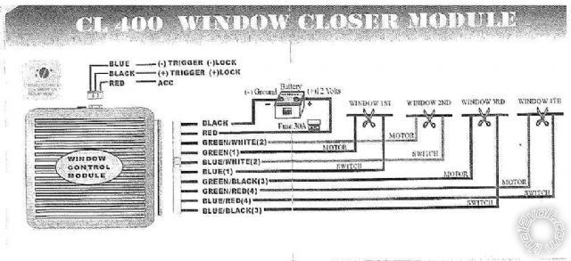 ------------- thanks for you help i needed all i can get!!!!!!!!
Replies:
Posted By: unique316
Date Posted: March 01, 2010 at 10:44 PM
What are you having trouble with? Not being a smart ass, LoL I promise. A simple way to look at it is..... 12+ to a constant power source. as far as the wires that go to the windows if you look one goes to the switch the other goes to the motor for example WINDOW 1 cut the wire and the wire that needs the switch lead trace which ever side goes to the switch and vise versa for the motor lead. now if the lead for the alaarm is negative then you are going to use the blue trigger or if the alarm is requiring a positive then you use the other trigger. this module is universal you may need to isolate with a relay deopending on what ouput you are using on your alarm. What alarm model do you have ? ------------- YES....OR....NO..?
Unique
Wichita, KS
Posted By: howie ll
Date Posted: March 02, 2010 at 1:17 AM
Pick up the lock trigger from the alarm before the resistor and wire it to the blue wire on the smaller plug. After the join place a diode (1N4004) in line before the resistor with the band towards the join you've just made.
Posted By: andrew00perez
Date Posted: March 02, 2010 at 1:38 AM
oh so i only need to use one wire  not both (+) and (-)
i tried to use both and popped the fuse.
what is the acc wire for 
so does that mean that when the trigger is not closed (activated) then the window connection is (closed) shunted so it works like normal
would the diode be so it would not roll up when i lock the doors for the door switch only from the alarm ------------- thanks for you help i needed all i can get!!!!!!!!
Posted By: andrew00perez
Date Posted: March 02, 2010 at 2:05 AM
im using a prestige APS-920a
the lock output(red)is a pulsed ground with 250 mA max
so doing a little search on here does this diagram make since
+12 red = Red (ignition harness)
-12 black = common ground
(-) trigger = Red lock output(-) on alarm*
*add diode to lock output before resistors line facing window module
LF (window 1)= Brown (driver door switch)
RF (window 2)= Light Blue (driver door switch)
LR (window 3)= Dark Green (driver door switch)
RR (window 4)= Light Green (driver door switch)
-------------
thanks for you help i needed all i can get!!!!!!!!
Posted By: howie ll
Date Posted: March 02, 2010 at 4:15 AM
Maybe the ACC is a standoff to prevent the windows closing if you lock the door with the ignition on. The diode insert I suggested does the same thing.
You need to connect both the + and the -. Make sure your closer outputs are connected to the window motor wires the right way round!
Posted By: andrew00perez
Date Posted: March 02, 2010 at 11:36 AM
so just to make sure my alarm only has a (-) locking output
should i connect the (+) trigger to a full time power may be even just tap it into all time power wire for the module
and then just connect the (-) trigger to the grounding output to close the curcuit
and put the acc wire to the igition acc wire just for $#!ts and giggles
and check it before i put a rectifier diode
-------------
thanks for you help i needed all i can get!!!!!!!!
Posted By: howie ll
Date Posted: March 02, 2010 at 11:57 AM
No connecting the grounding wire to your lock output will at least blow your lock circuits on your unit. Use the ground at your window switch if you mounted it in the driver's door, other wise find a body bolt and use that.
Posted By: andrew00perez
Date Posted: March 03, 2010 at 1:16 AM
i was thinking the trigger neg
not the unit power neg is this wrong
-------------
thanks for you help i needed all i can get!!!!!!!!
|