used car with alarm, 04 tundra, code alarm
Printed From: the12volt.com
Forum Name: Car Security and Convenience
Forum Discription: Car Alarms, Keyless Entries, Remote Starters, Immobilizer Bypasses, Sensors, Door Locks, Window Modules, Heated Mirrors, Heated Seats, etc.
URL: https://www.the12volt.com/installbay/forum_posts.asp?tid=121399
Printed Date: April 30, 2026 at 3:14 PM
Topic: used car with alarm, 04 tundra, code alarm
Posted By: j.w.
Subject: used car with alarm, 04 tundra, code alarm
Date Posted: April 17, 2010 at 10:46 PM
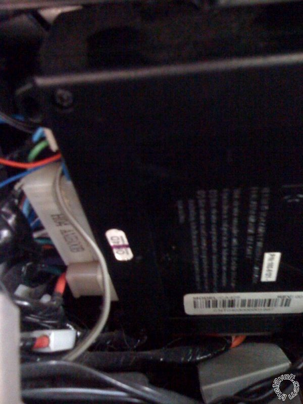
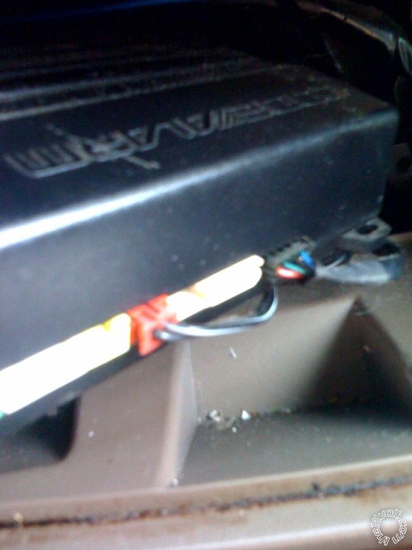
I recently bought a 2004 Toyota Tundra double cab. It did not come with keyless entry remote. I dug around and saw that it has an alarm installed. I opened up the dash and found the module. It's a Code Alarm 425, p/n 102-5121. I've contacted Code Alarm about ordering some replacement parts to get this back to being operable. I have read some pretty bad reviews about Code Alarm, so i'm not counting on them being able to help me out very much. Does anyone have experience with this scenario? Would i need to simply buy a new remote, or replace the entire system? I'm ok with replacing the whole thing if need be. If I bought the same module(s), would it pretty much be "plug-n-play"? Any direction on the next steps i need to take would be greatly appreciated. All i'm really trying to achieve is getting keyless entry, but if the modules/wiring is already there, i wouldn't mind having additional feature. Would it be as simple as just buying one of these?
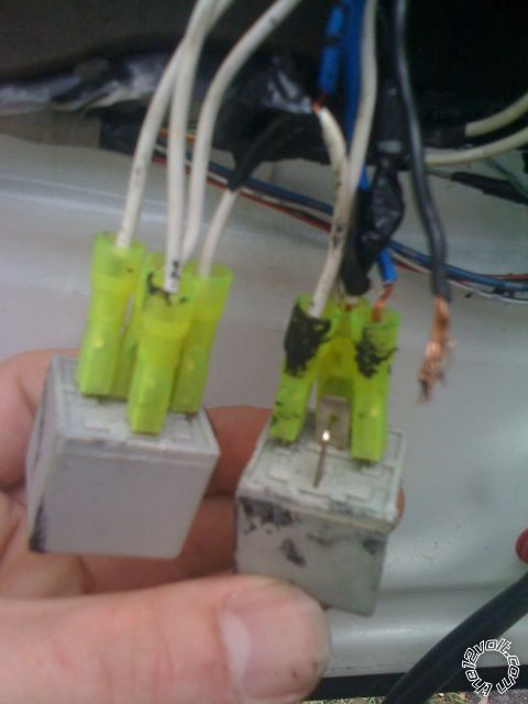
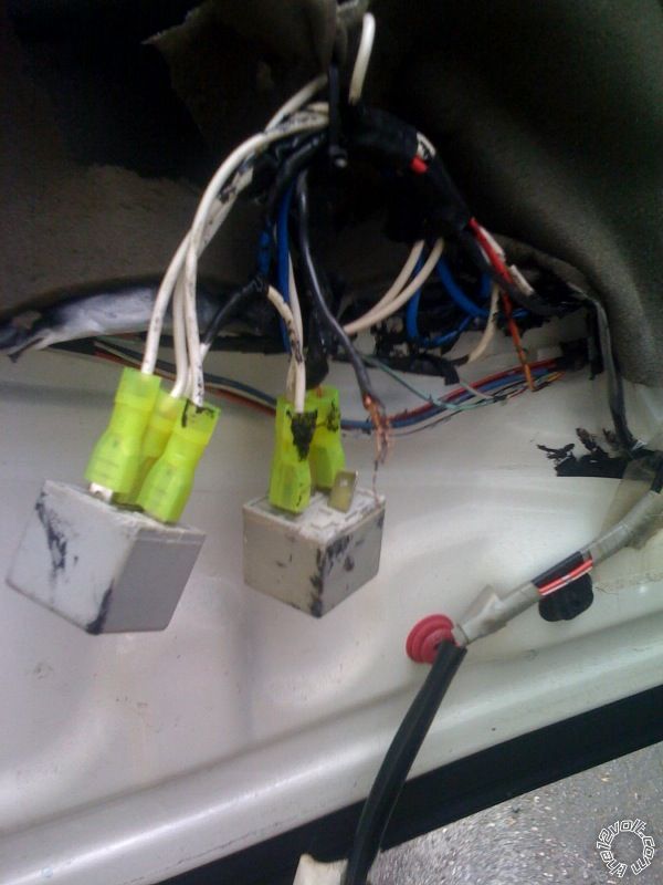
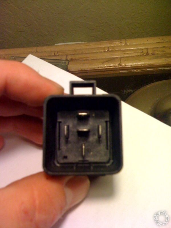
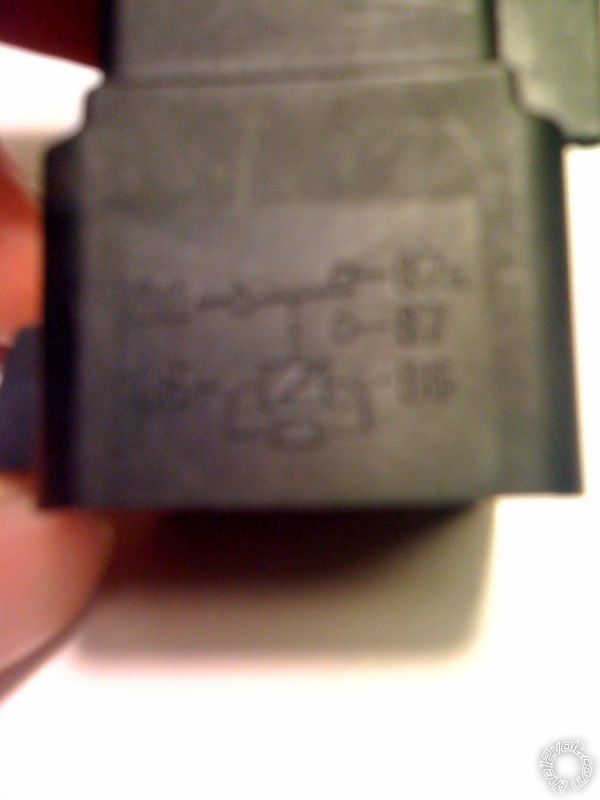
PART 2: I did some more exploring and took off the driver's side door panel and found a couple gray cubes with some half-*** wiring (pics attached). I'm assuming these are for the keyless entry add-on? Check out the pics...where is that black wire supposed to be attached?! For a while now, i've been having some strange behavior with the locks...
- After opening the door with the key, the unlock button does not unlock the other doors. Have to manually reach over and push the lock lever back. However, with the car started, the locks work fine.
- When key is in ignition, if i lock the doors with the lock button, they all immediately unlock. I have to remove the key from the ignition to be able to lock my doors.
These problems must be a result of that crappy wiring job in the driver's door. Any thoughts on how to troubleshoot this? I'm sure it's more complicated than "hook up the black wire where the blue wire is" (that's actually where it looked like it was probably hooked up), but i'm willing and eager to learn more. I'm very inexperienced with alarm systems, but have installed a few audio systems. I'm a do-it-yourselfer, and will research and learn whatever i need to. just looking for some starting points. I'm more than happy to pull off the dash and door again to gather any additional info (pics, diagrams, etc) that will help troubleshoot this.
Thanks you in advance for the help.
Replies:
Posted By: j.w.
Date Posted: April 17, 2010 at 10:49 PM
sorry, i don't think my link "these" is working. I was referring to the Code Alarm Basic Security Keyless Entry CA-125 NW.
thanks again,
j.w.
Posted By: mikvot
Date Posted: April 17, 2010 at 11:54 PM
Code Alarm (aka) Audiovox makes bulletproof equipment. As for the doors unlocking with the key in the ignition....this is a fucntion of the vehicle. It helps prevent you from locking the keys inside the vehicle. I can provide you with proper wiring for the door locks, but since you refered to Relays, as "little gray cubes".....i'm sort of scared.....but i will find it for you. Good luck!
Posted By: mikvot
Date Posted: April 17, 2010 at 11:58 PM
Here ya go! Have fun. Just to add, If I were in your position, I wouldn't even mess with the previous installers wiring. I would just start from scratch.
Posted By: j.w.
Date Posted: April 18, 2010 at 12:29 AM
that did come out a bit harsh on Audiovox. Honestly, i only read a couple of reviews on the CA-425; I shouldn't have lost faith so quickly!
mikvot wrote:
Here ya go!
wow. that pdf really clarifies the mystery of the "gray cube". lol. no need to be scared, but yeah, that did sound like something my girlfriend would say :) seriously, thanks for that PDF. I'm all for re-wiring it. do you happen to have a source for any documentation on the CA-425? I'm excited to not have to lean across my full-size truck cabin to let in a passenger. ha.
i think i can tackle the relay repair. now...how can i talk to the CA-425? with the CA-125?
and thanks for the awesomely informative and quick response.
Posted By: j.w.
Date Posted: April 18, 2010 at 1:22 AM
I came across this in another thread from a few years back. Does it look accurate?
CA-425 Wiring Diagram:
4 Pin Power Harness
1 +12 Volts - Red
2 Starter Input (keyside) - Green
3 Starter Output (motor side) - Purple
4 IGN 1 Input/Output - Pink
22 Pin Base Harness
1 Dome Light Output - BLACK/ White
2 Manual Arm Input - Lt.Blue/Red
3 Unlock Switch Input - Lt.Blue/Green
4 Trunk Pin - Blue
5 Instant Trigger - Blue/White
6 Remote Start Activation - WHITE/ Blue
7 Hood Pin Input - Gray
8 Parking Brake - Gray/Black
9 Negative Door Trigger - Green
10 Ground - Black
11 Positive Siren Output - Brown
12 Parking Lights - White
13 Channel 1 - Pink
14 Manual Disarm Input - Lt.Blue/Black
15 OPEN - OPEN
16 Positive Door Trigger - Purple
17 Wait To Start - BLACK/ Gray
18 Headlight Output - Lt.GREEN/ Orange
19 Songbird Output - BROWN / White
20 Horn Output - BROWN / Black
21 Tach Input - PURPLE / White
22 Armed Output - Orange
source: https://www.the12volt.com/installbay/forum_posts.asp?tid=65701&get=last
Posted By: j.w.
Date Posted: April 18, 2010 at 2:34 AM
i found the installation manual. looking at the diagrams, and comparing them to my photos, it appears that the truck is wired for remote start. sweet.
it appears that the CA-425 was the brain of a few code alarm kit model #'s, and they came with different features and remotes. i think all i need to do is re-wire those relays, and then buy and program this remote, and I will be good to go, right? does the FCC ID of the remote that i buy need to match the FCC ID of my 2 way antenna?
Posted By: howie ll
Date Posted: April 18, 2010 at 7:14 AM
Grey cubes 
Posted By: j.w.
Date Posted: April 18, 2010 at 10:22 AM
howie ll wrote:
Grey cubes
lol. i know. i know. that was pretty rookie!
and here's another one... does the FCC ID on the back of my 2-way antenna need to match that on the remote? My antenna's ID is ELVNTRCB. All of the replacement remotes that I can find online are ELVNTRCA. I'm assuming this is ok, but want to be sure before I order it (no returns).
Posted By: j.w.
Date Posted: April 18, 2010 at 10:36 AM
and one more :) ... is it safe to assume that the second relay is for remotely controlling the windows, or could it also be for the locks? my truck is a double cab with 4 power windows, power rear window, and a sunroof.
thanks!
Posted By: howie ll
Date Posted: April 18, 2010 at 12:13 PM
Locks only, windows would have separate closing units if present.
Actually you shouldn't need relays to control Toyota locks unless I'm missing things, it's a US vehicle and I've never seen one.
Posted By: j.w.
Date Posted: April 18, 2010 at 1:07 PM
Posted By: j.w.
Date Posted: April 18, 2010 at 1:09 PM
Not sure why that first image didn't work. Here it is in PDF... Here
Posted By: j.w.
Date Posted: April 18, 2010 at 2:39 PM
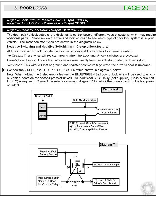
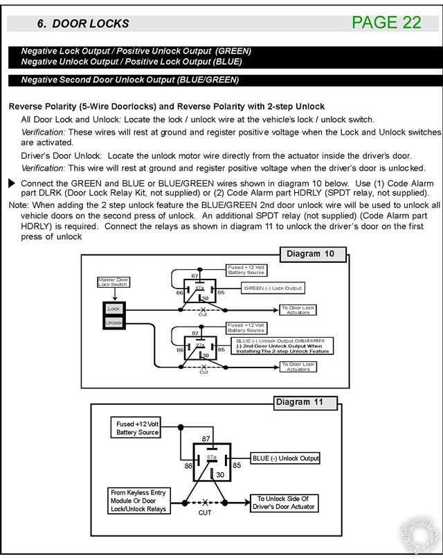
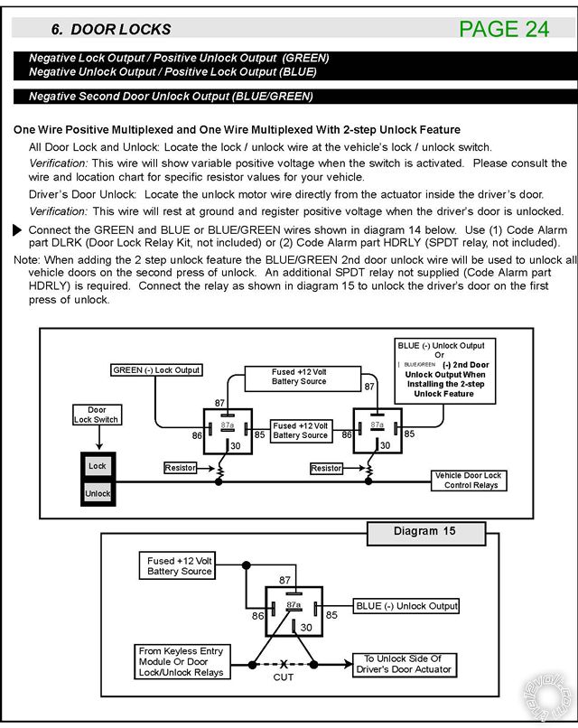
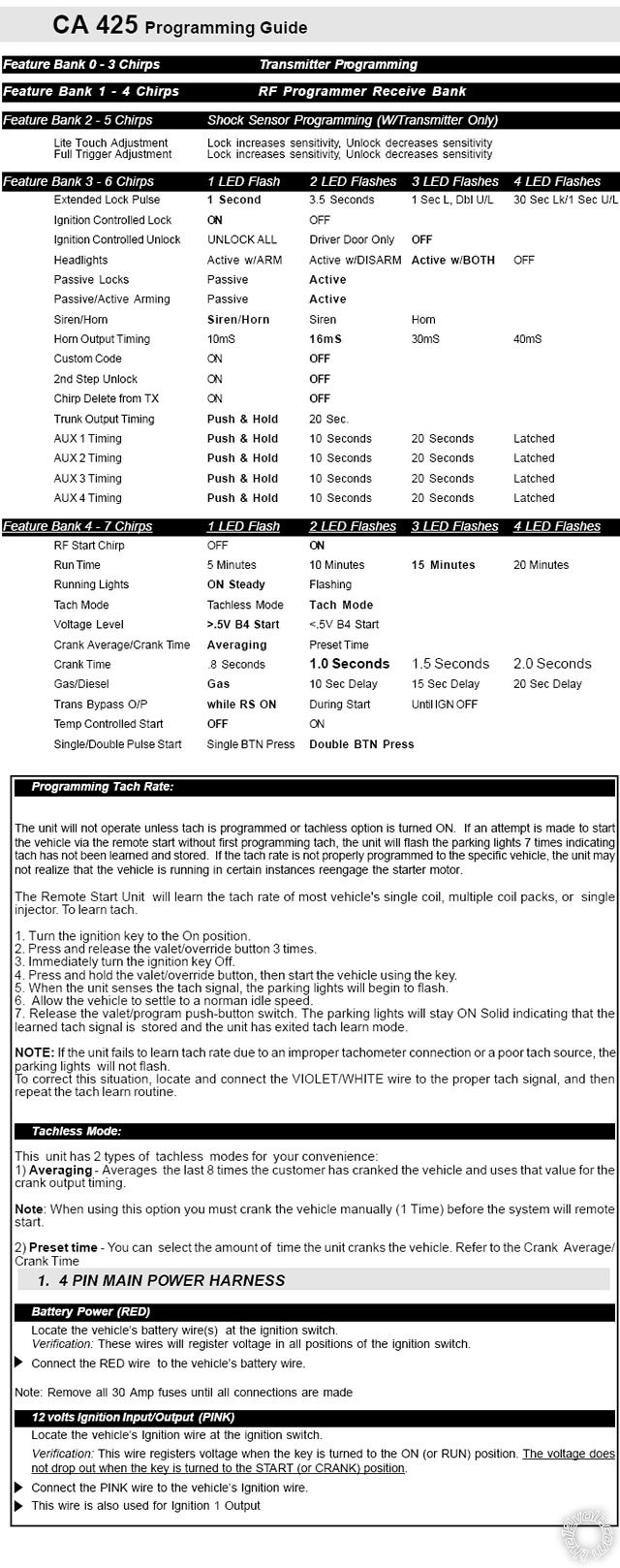
i'm thinking i need to follow diagrams 10 and 11 on page 22??
Posted By: howie ll
Date Posted: April 18, 2010 at 5:41 PM
I'm probably going to get shot down over this but I did an RX recently, went straight to the actuator wiring at rear of driver's door found the trigger wires, NO RELAYS REQUIRED and I extended the lock timing pulse to give me window and roof close. EASY!
If I'm wrong, use the first diagramme shown.
Posted By: j.w.
Date Posted: April 18, 2010 at 6:18 PM
lol. thanks for the tip :) I THINK i'm all set. I went out there today and cleaned up those wires a bit, and every thing seems to be working ok now. I think there was just a loose wire that was causing some issues. We'll see, but it appears ok now.
i think all i need to do is buy this remote, program it, and i'll be all set. Does the FCC ID on the back of my 2-way antenna need to match that on the remote? My antenna's ID is ELVNTRCB. All of the replacement remotes that I can find online are ELVNTRCA. I'm assuming this is ok that they don't match, but I want to be sure before I order it (no returns). I confirmed that the model of the remote will work with my system, just not sure about the FCC ID's.
Posted By: lectricguy
Date Posted: April 19, 2010 at 4:39 PM
j.w.- The FCC IDs for the 2 way antenna and remote will be different. These ID's are refering to FCC filings for radiated emissions of transmitting components. The first 3 characters identify the grantee, the subsequent characters specify the file. https://www.fcc.gov/oet/ea/fccid/ The ID's you posted are both for remotes...You may want to recheck the ID's and confirm they are both at the same frequency. Most likely, they are compatible. ------------- Lectric Guy
Posted By: lectricguy
Date Posted: April 19, 2010 at 4:56 PM
Update- The report the FCC lists for the ELVNTRCB is for the antenna, as evidenced by the set up pictures. The external and internal photos are of the ELVNTRCA remote. FCC documentation mistake...go figure... ------------- Lectric Guy
Posted By: j.w.
Date Posted: April 19, 2010 at 5:22 PM
right on. thanks lectricguy. yeah, i contacted a company that sells the replacement remotes, and they said that it will work with what i have. I should have it by the weekend. Now i just need to figure out how to program it :) I'm sure there is documentation somewhere out there, probably on this site (12volt.com rocks). I'll give it a go, and update ya'll on what happens! of course, any pointers are always welcome and appreciated.
Posted By: lectricguy
Date Posted: April 19, 2010 at 7:17 PM
j.w.- Once you receive your replacement remote, refer to the top of page 8 of the installation manual (Transmitter programming). The procedure is straightforward. Let us know if you need help.
------------- Lectric Guy
Posted By: j.w.
Date Posted: April 23, 2010 at 5:03 PM
ok. making SOME progress. I received the remote today and attempted the programming. I'm able to get the remote to talk to the unit, and can achieve arming and disarming the alarm. However, i am unsuccessful with getting the keyless entry or remote start functions working. To be honest, i don't even know which button on the remote is supposed to initiate the remote start. I can't find any documentation on the remote (CA5BLETX). During programming, i'm able to cycle through the banks and change the settings as described below. I was even able to program the tach rate sucessfully.
what would be my next step troubleshooting this system? Like i said, i bought this vehicle used, so i don't even know for sure that the system was functioning properly before. Any way to do some basic troubleshooting to see if i'm spinning my wheels here?
here's another thread i found on this system. it's pretty negative, but i'm determined to get this working. Everyone on this forum has been extremely helpful so far and i'm optimistic. thanks!
Posted By: j.w.
Date Posted: April 23, 2010 at 5:19 PM
oh yeah, one more question. there's an on/off toggle switch next to the override button. any idea what that is? what it should be set to?
thanks again
Posted By: j.w.
Date Posted: April 23, 2010 at 5:47 PM
ok, got remote start to work. i think i did it by holding down the OPT button for a few seconds, letting it go, and then pressing it again.
still no luck with the door locks though.
Posted By: j.w.
Date Posted: April 23, 2010 at 6:25 PM
still no luck with the keyless entry. I can't get any action from the locks. I THINK that when i was messing with it that it unlocked the doors once, but i may have been dreaming. If so, it only happened one time, but if it did, that means that it's at least able to work if i could just configure it properly. Man, these things are complicated.
I'm SO close...
Posted By: j.w.
Date Posted: April 23, 2010 at 6:33 PM
sorry for all the posts, but does anyone know where if can find documentation on my remote (CA5BLETX)? i'm figuring all this out by just pressing buttons. It's making some random series of beeps, flashes, etc. Half of which i have no idea of what they mean. Sure would be easier if i knew what they meant!
Posted By: lectricguy
Date Posted: April 23, 2010 at 7:28 PM
JW- For information on the remote, you may want to look at the CA 670 User's Manual: https://www.the12volt.com/installbay/file.asp?ID=507 This should give you some idea of how the remote operates. As far as the toggle switch, that disables remote start on Code Alarm units. When open (or off), the remote start function is disabled. When closed (or on), the remote start function is enabled. I agree with Mikvot from earlier in this post--you may want to rewire the locks from scratch.
------------- Lectric Guy
Posted By: j.w.
Date Posted: April 23, 2010 at 10:02 PM
Thanks for that link! That's looks like how mine's wired from what I can tell. Not too much more info on the remote operation though. Would be nice to know what all those different series of beeps mean. I was sitting on the couch after I was home for about an hour, and it randomly played a melody!? Lol. I figured out how to activate the remote start by pressing diff button combinations. Still not sure exactly how to do it. My remote only has a Lock, Unlock, OPT, and F button.
I agree with rewiring the doors. Still unclear as to which diagram to follow. I sketched out exactly how mine is currently wired. I'll do my best to draw an amateur diagram in Photoshop. Maybe it's an obvious thing that you'll spot right away.
Thx
Posted By: j.w.
Date Posted: April 24, 2010 at 11:06 AM
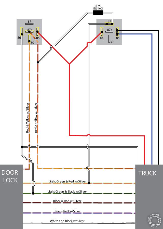
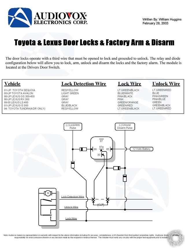
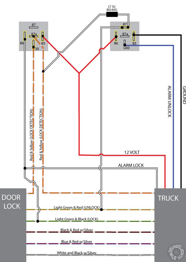
I opened up the door panel and traced the wires. I sketched it out and did my best to put together a diagram in Photoshop (below). Please excuse how amateur it is. For quick reference, I've also attached the vehicle specific Audiovox diagram that mikvot provided earlier in this thread.
The Audiovox diagram looks spot on as far as the colors of my wires and how they're tied in to one of the relays. I just can't figure out how that second relay comes in to play. The diagrams in the CA 670 manual don't really look anything like what i have hooked up, but i may be reading them wrong.
Anyways, just thought ya'll might be able to spot something right away that looks out of place. There is one spot (87) on that relay on the right side of my diagram that i'm really questioning. When i opened the door up, one of the two wired connected to it was loose. It looked to me like it was supposed to go there (complete guess), so i hooked it up.
Thanks again for all the help.
Posted By: j.w.
Date Posted: April 25, 2010 at 2:16 PM
lectricguy, i apologize. that manual has tons of great info on my remote and it's functions! Thanks!
Posted By: j.w.
Date Posted: April 25, 2010 at 4:33 PM
Ok, system and remote are programmed/configured, and thanks for that User's Manual link, I now know what all the sounds mean :)
However, still no lock action. I think I need to rewire them from scratch. Should I just remove the second relay and wire exactly like the vehicle-specific audiovox diagram with one relay? Just afraid that second relay is there for a reason :/
I guess it's also a possibility that the relays have gone bad. Where could I get a replacement relay? Are these standard electrical parts or do I need to order them from Audiovox?
Thanks for the help!
Posted By: lectricguy
Date Posted: April 25, 2010 at 6:25 PM
j.w.- Great diagram...this will help debug what is happening. This is what I see: 1.) Relay on the left side of your diagram is the lock relay--this is hooked up correctly. 2.) Relay on the right side is your unlock relay, and this wired incorrectly. Instead of using 2 diodes, the unlock looks like it was hooked up with 1 diode and a relay...not sure why it was done this way, but this setup can be made to work. Here is what you need to do to correct it. If you trace back the blue and black wires connected to the unlock relay pin 85, I'll bet blue is going to CA425 negative unlock signal (Blue from the Brain's lock/unlock connector). My guess is black wire is going to ground. You need to confirm this. If this is the case, remove ONLY the black (Ground) from pin 85 (leave the Blue unlock signal from the brain on pin 85) and connect the black wire to pin 30. You end up with the following connections on your unlock relay: Power (+12V) on Pin 86 Remote Start negative unlock (blue from Brain Lock/Unlock connector) signal on pin 85 Diode from lock detect and vehicle unlock signal (light green and RED / silver) on Pin 87 Ground on Pin 30
------------- Lectric Guy
Posted By: j.w.
Date Posted: April 25, 2010 at 7:48 PM
that did it! thanks! i now have 2-stage unlock keyless entry. however, the doors do not lock when i arm the system. could this be an optional setting? I see that i can toggle "Passive Locks" in programming; could this be it? I had to call it a night, but will try changing the setting tomorrow to test it.
thanks again!
Posted By: lectricguy
Date Posted: April 25, 2010 at 8:16 PM
j.w.- Active locking or arming requires you to use the transmitter to lock & arm the vehicle. It should both lock and arm when you press the transmitter lock button. Passive locking or passive arming will automatically lock or arm (you can select either or both to be passive) 1 minute after the last door is closed, or if the transmitter lock is pressed. If the doors are not locking when you press the transmitter, I would check to make sure the lock relay is activating (you can hear the click, or feel the relay while pressing the lock button on the transmitter). If it is not, make sure the connections to the relay are good (i.e., not loose or initermittent). The diagram you provided is correct; if the wiring is good, you may have a faulty relay. ------------- Lectric Guy
Posted By: j.w.
Date Posted: April 25, 2010 at 9:00 PM
gotchya. i will confirm connections and wiring. would this work as a replacement relay?
also, could you recommend the best parts for re-wiring this properly? as of now, the wires are all spliced and connected by twists and electrical tape. I'm sure there is a better way, right? Thanks man. I'm pretty inexperienced with this, but really enjoying learning!
Posted By: j.w.
Date Posted: April 25, 2010 at 9:06 PM
oh, and on another note, the alarm has been going off randomly. I thought it might be the shock sensor, so i disabled it (in programming, decreased the sensitivity one click past the lowest setting). But it happened again. Any idea what this could be?
Posted By: lectricguy
Date Posted: April 26, 2010 at 9:09 AM
1.) The relay you identified will work. I would make sure all your connections are good first before changing the relay. If the connections were made poorly, the wiring is more likely the cause of failure or intermittent operation.
2.) There are many opinions on the best method of connection; if any of the methods are not done correctly, they can be problematic. I prefer soldering the connections, then taping the connection with high quality electrical tape. Others prefer using crimp connections, and others prefer twisting the wires together, taping and adding a tie wrap over the tape to keep things tight. They all work if done correctly, but if not done properly, any approach will eventually fail.
3.) As far as the alarm triggering, you should have an LED from the CA425 somewhere in the vehicle that indicates it is armed (note that sometimes this LED is not in an obvious place, but you should be able to trace it from the brain). When the alarm is triggered and either disarmed by the transmitter or completing the alarm cycle (30 seconds, I believe), the LED flashes a specific number of times indicating what caused the alarm to trigger. From the CA 425 install manual:
The LED flashes a number of times to indicate which input triggered the alarm:
Number of flashes:
1 - Interior Theft Sensor (Shock Sensor)
2 -Hood/Trunk input 3 - Door Input
Please note the LED clears when you turn the ignition on. I would check the LED status after the next trigger event to help isolate the problem.
-------------
Lectric Guy
Posted By: j.w.
Date Posted: April 26, 2010 at 3:43 PM
The alarm went off again, and i confirmed that it was the shock sensor - single flash. I went back and adjusted the shock sensitivity. I noticed that there were two options under that - "Light Touch" and "Full Trigger" (btw, what's the difference?). I had "light touch" disabled, but "full trigger" was still set to a pretty high sensitivity. I went ahead and disabled that as well. We'll see if that does the trick!
I checked the wiring on the relay, and everything SEEMED to be ok. I will probably go ahead and rewire it, and see if that does the trick. If not, i'll replace the relay. I found this relay at Radio Shack. Will it work? It would save me on shipping cost and transit time if i could pick that up from a nearby "Shack".
Posted By: lectricguy
Date Posted: April 26, 2010 at 5:02 PM
j.w.-
For the shock sensor, "light touch" is a pre-trigger/warning setting, and will not initiate a full alarm trigger, just warning chirps. "Full trigger" is the full alarm trigger.
The Radio Shack relay is only SPST(single poll/single throw) with a normally open contact. The relay you need for the replacement of your lock relay would be SPDT (single pole/ double throw), or SPST with a normally closed contact. Bottom line-it won't work for your lock relay application.
As a note, I have seen 12V SPDT relays at Pep Boys--in the same display where they have Bulldog Security Remote Starters. They are listed as 40A relays from A2C, the company that markets Bulldog. ------------- Lectric Guy
Posted By: j.w.
Date Posted: April 26, 2010 at 10:31 PM
Thanks for the clarification on the sensors.
I stopped by Pep Boys and picked up a relay (pics below). I confirmed the connections and then replaced the relay, but still no luck :( What would be my next step?
Thx
Posted By: howie ll
Date Posted: April 27, 2010 at 2:53 AM
We appear to be running around in circles here guys, some thoughts that may cast light on the problems.
Why 2 relays? I appreciate using the one with diodes as per the Audiovox diagramme but why 2?
I've never used a relay for the locks on a Toyota except the UK IS Lexus where you need to get to the motor wires.
I'll take this a stage further, I did 2 Harriers/Lex RX recently where I went into the driver's door, connected to two wires low current neg at the rear of the door, lock and unlock, extended pulse for comfort close, no relays, no diodes! I've got photos as proof!
Test the locks to see if you can make the locks work you should only need a decent test light, also test the units lock and unlock outputs.
Posted By: lectricguy
Date Posted: April 27, 2010 at 5:24 AM
Howie- Good point. I believe j.w. bought the vehicle with the system installed that way--no idea why the installer used 2 relays. The one not working is the lock relay per Audiovox diagram--the one in the unlock position--replacing a diode--works just fine. Making the existing circuit work might be the easiest if the output of the unit and the locks both work properly. Testing the lock circuit and unit lock output with a test light or multimeter is the correct next step. ------------- Lectric Guy
Posted By: j.w.
Date Posted: April 27, 2010 at 12:24 PM
that's correct. it was installed that way, so i have no idea why there are two relays, but i'm willing to try whatever setup it takes to get it to work.
Ok, so i picked up a DMM today and did a bit of testing. Here's what i found...
LOCK TEST(tested by probing the wire right before pin 86 of the lock relay)
Resting = 9.21
Press Lock = 11.9
Press Unlock = 11.5
even though the unlocking is working fine, i decided to test that too...
UNLOCK TEST (tested by probing the wire right before pin 30 of the unlock relay)
Resting = 10.99
Press Lock = 10.93
Press Unlock = 0
now, what does this mean? :)
Thanks guys. Let me know if you need me to test anything else to help troubleshoot.
Posted By: lectricguy
Date Posted: April 27, 2010 at 4:28 PM
Confirm that there is +12V constant on pin 85. On pin 86, which comes from the remote start lock output, should be pulsing to ground for 1 second when lock is pressed. When this occurs, the relay will open pins 30 & 87a, which are closed (connected) when the relay is at rest.
------------- Lectric Guy
Posted By: j.w.
Date Posted: April 27, 2010 at 4:37 PM
will do. thx man. sorry, what does "pulsing to ground" mean?
Posted By: lectricguy
Date Posted: April 27, 2010 at 4:43 PM
The output provides a 1 second momentary ground. Put the positive meter lead on 12V, the negative meter lead on pin 86. The meter will read 12V when the lock button is pressed if the output is working correctly. ------------- Lectric Guy
Posted By: j.w.
Date Posted: April 27, 2010 at 5:59 PM
Ok, just tested as you described. It reads 3.5v at rest, and when I press the lock buttononthe remote it reads 0.6v for a second 0r two. Any idea what could be causing that? Also, I confirmed that pin 85 reads 12v constant. I put the negative lead on a bare piece of metal on the body for ground.
Posted By: j.w.
Date Posted: April 27, 2010 at 6:15 PM
I put the original relay back in place and getting different numbers - 12v at rest and 4v when I press the lock button. When I press unlock, it drops to 1v.
Posted By: j.w.
Date Posted: April 27, 2010 at 6:20 PM
Not sure if this matters, but when I put positive on 12v (85) and negative on 30, it reads 12v at rest, and 11.8 when I press the lock button. Same with pin 87a.
Posted By: j.w.
Date Posted: April 30, 2010 at 12:06 AM
i took some more readings. no idea what they mean, but having fun doing it. :) Maybe these numbers will help troubleshoot. Thanks!
AT REST: 85---87 = 0 volts
AT REST: 85---87a = 12
AT REST: 85---86 = 12
AT REST: 85---30 = 12
AT REST: 86---87 = 0
AT REST: 86---87a = 0.16
AT REST: 86---30 = 0.16
AT REST: 87a---87 = 0
AT REST: 87a---30 = 0
PRESS LOCK: 85---87 = 0 volts
PRESS LOCK: 85---87a = 12
PRESS LOCK: 85---86 = 4
PRESS LOCK: 85---30 = 12
PRESS LOCK: 86---87 = 0
PRESS LOCK: 86---87a = 8
PRESS LOCK: 86---30 = 8
PRESS LOCK: 87a---87 = 0
PRESS LOCK: 87a---30 = 0
Posted By: howie ll
Date Posted: April 30, 2010 at 12:34 AM
Frankly not a thing, hence use a test light or by-pass the lock side relay!
Posted By: j.w.
Date Posted: April 30, 2010 at 8:01 AM
sorry, so you're saying i should use a test light and take the same readings as above? I read a post somewhere ( here actually) that a test light would damage the electronics of my Toyota. Not sure how.
How would i bypass the lock side relay? Can you give me specifics or point me in the right direction?
thanks
Posted By: howie ll
Date Posted: April 30, 2010 at 12:34 PM
It won't damage what you're working on. The questions you are asking are so basic it's difficult to answer!
Take the wire from your alarm directly to vehicle wire.
Look at the diagramme on page 2.
Posted By: j.w.
Date Posted: April 30, 2010 at 1:16 PM
yeah, sorry man, i'm very rookie. i do appreciate ya'll bearing with me and walking me through all of this.
looking at my current diagram, you're saying i should splice the ALARM LOCK wire directly into the LOCK wire, completely bypassing the relay, correct?
Should i also take the LOCK DETECTION wire off of the relay and splice it back together? What about the wire coming off of that going into 87 of the unlock relay on the right side of the diagram? leave it or lose it?
thanks again. i really do appreciate the help.
Posted By: lectricguy
Date Posted: May 01, 2010 at 11:56 AM
j.w.- I was traveling for a few days and unable to get on...at this point, you have 2 options--Get the existing circuit working (I believe you are fairly close), or take the relays out and go the the lock motors as Howie suggests. Not sure where you are with this, but if you decide to go to the motors, yes, you need to splice lock detect back together. Leaving the diode in place in the unlock circuit would not harm anything. ------------- Lectric Guy
Posted By: j.w.
Date Posted: May 02, 2010 at 12:25 AM
hey man. hope your travels went well. Today, i tried by passing the lock relay, and left the unlock relay in place, but no luck. Now remote unlock is not functioning. Should i remove both relays?
I was thinking next i could try the Audiovox diagram (page 2 of thread) with the one relay and four diodes. I picked up some diodes at Radio Shack, but not sure if they are suitable. They're "1.5A, 1000-PIV silicon diodes". Will these work?
thx
Posted By: howie ll
Date Posted: May 02, 2010 at 2:20 AM
Yes to you last 2 questions, those diodes are over the top but fine, $1.99, bloody hell, I pay 1c each for 1N4004's in bulk 
Posted By: tedmond
Date Posted: May 02, 2010 at 6:24 AM
that is expensive for diodes ahah. try local electronic shops such as tv repair shops. they will sell you a few for no more than a dollar for a few, hell they might even give it to you. ------------- Ted
2nd Year Tier 1 Medical School
Still installing as a hobby...pays for groceries
Compustar Expert
Posted By: j.w.
Date Posted: May 02, 2010 at 8:29 AM
glad to hear those diodes will work. Damn Radio Shack; such a ripoff but right around the corner from my house. Already picked them up yesterday.
ok, here's the plan today....
1. Remove the second relay, cap off the ground wire and the 12v wire, and splice the alarm unlock wire directly into the unlock wire (alarm lock is already spliced to lock wire, and lock detection is spliced back together).
2. If no luck with #1, I will wire just as the Audiovox diagram (page 2 of this thread) shows with one relay and four diodes.
While i have this apart, are there any readings that i can take with the multimeter that will help isolate if this is a problem with the alarm brain or wire coming from inside the vehicle?
Today's the day. It's gonna work!
Posted By: j.w.
Date Posted: May 02, 2010 at 11:08 AM
alright, still no luck. Tried option 1 and 2. Option 1 gave no remote lock or unluck. It's wired as option 2 now, and the remote unlock works, but still no remote lock. Not sure what to do next. Maybe the trigger in the alarm brain is bad? could it have gotten shorted out?
Posted By: howie ll
Date Posted: May 02, 2010 at 11:33 AM
This has gone past ridiculous, buy a test light or even rig up a bulb and test your lock/unlock outputs from your alarm. Place one side of the test bulb to a constant 12V live and the other side to each in turn. Let's see if the unit is working first. Don't use a DMM, it's giving you too much info.
Posted By: lectricguy
Date Posted: May 02, 2010 at 2:33 PM
j.w.- So right now, you have the Audiovox circuit wired in, but lock doesn't work (same starting point as before, only now we are down to 1 relay...). 2 key questions: 1.) do the doors lock from the doorlock switch on the door? 2.) with your previous (initial) set up, you had the unlock relay working....did you use that relay for this? If not, please revert to that relay... Please post your answers. I believe we can make this work... ------------- Lectric Guy
Posted By: j.w.
Date Posted: May 02, 2010 at 4:39 PM
1) yes, same as before. door locks function as they should. remote unlock works; just no remote locking.
2) yes, using the unlock relay.
and here's one more bit... i was driving down the road, hit a bump, and all the doors locked. ?? probably loose wiring somewhere, huh?
i don't have a test light, but can pick one up tomorrow and give it a try.
thanks!
Posted By: lectricguy
Date Posted: May 02, 2010 at 4:47 PM
j.w.- Yes, could be a loose wire, but let's get more info. 1.) When you try to lock using the Code Alarm remote, does the relay click or energize(this may seem trivial, but it is important...)? Can you hear the relay/feel the relay when you press lock? ------------- Lectric Guy
Posted By: j.w.
Date Posted: May 05, 2010 at 2:07 PM
sorry, been pretty busy with work, and haven't had a chance to mess with this. I'll try to go pick up a test light tonight, and get out there to take some readings as well as feel the relay to see if it's clicking. Will post the results in 6 or 7 hours if i can do it tonight.
thanks again,
j.w.
Posted By: j.w.
Date Posted: May 30, 2010 at 10:47 AM
my bad fellas. work has been crazy. i picked up a test light, but have not had a chance to do any testing. I actually have a bigger problem now. My tail lights are not functioning. Brake lights work fine, but no tail lights. I was just made aware of it, but i think it's been the case as early as halfway through this thread. Could this have been a result of me removing that second relay? not sure how it could. I've checked the tail lights fuse, and it is fine. The bulbs are fine b/c it's the same bulb as the brake lights and that works fine. I guess my next step is to isolate the problem in the circuit. Using my multimeter and/or test light, what would be my next step?
I'm still not giving up on the lock relay, just need to tackle this first. Thanks, J.W.
Posted By: afg_capone
Date Posted: May 30, 2010 at 10:56 AM
check for power and ground. have someone press the brake pedal and stick your test light on one of the pins in the tailight socket and ground the test light wire to a known good ground. if you get the light on then check with a multimeter if you get 12v across the two terminals when the brake is pressed. if you dont get the light on then check the other terminal. if light goes on, then your problem lies the ground wire, if it doesnt then its the power wire. lemme know what happens
Posted By: catback
Date Posted: May 30, 2010 at 11:28 AM
The brake light and parking light are in the same bulb but use a different filament so the bulb can be bad if one (brake or parking) light doesn't light up. If all 4 parking lights don't work it's not very likely the bulb but if it's isolated to one or two lights then the easiest thing to do is check the bulbs.
Posted By: j.w.
Date Posted: May 30, 2010 at 11:30 AM
good to know! i bought some new bulbs just in case. I'm going to swap them out now and see if that works. will post back here in just a few. thanks!
Posted By: j.w.
Date Posted: May 30, 2010 at 12:47 PM
nice call. that was it. the second filament on both bulbs was toast. replaced with new bulbs, and i'm back in business. thanks again!
ok, back to the lock relay. not sure if i can work on it any more today, but will check it out as soon as i get a chance. i'm determined to get this working!
|
.jpg)