domelight and reverse lights h1/4
Printed From: the12volt.com
Forum Name: Car Security and Convenience
Forum Discription: Car Alarms, Keyless Entries, Remote Starters, Immobilizer Bypasses, Sensors, Door Locks, Window Modules, Heated Mirrors, Heated Seats, etc.
URL: https://www.the12volt.com/installbay/forum_posts.asp?tid=121605
Printed Date: April 29, 2026 at 5:37 AM
Topic: domelight and reverse lights h1/4
Posted By: jcs091570
Subject: domelight and reverse lights h1/4
Date Posted: April 30, 2010 at 3:22 AM
I am interested in adding a little feature to my dome light supervision function. I have my DEI H1/4 wire pushing a relay and connected to my negative dome circuit. I would like to tap into the H1/4 wire to also illuminate my reverse lights at the same time. But not when I open the door in general. Only on disarming and when removing key from ignition. I know I will need another relay but unsure of the connections. All the lights are LEDs and will draw minimal current. Any input would be appreciated thanks.
Replies:
Posted By: juavos00
Date Posted: May 05, 2010 at 10:05 PM
that would be sweet. I hope someone can answer your question as I may do that to mine aswell.. :)
Posted By: jcs091570
Date Posted: May 05, 2010 at 10:16 PM
Well I actually figured it out. If you are interested..let me know. I had to use a separate relay.
Posted By: juavos00
Date Posted: May 05, 2010 at 10:30 PM
definitely.. Please post it up here, and I may give it a shot. Thanks
Posted By: jcs091570
Date Posted: May 05, 2010 at 10:39 PM
Ok here it is, Pin 86 and Pin 30 go to fused constant 12v... Pin 85 goes to dome light output of alarm (Blk/Wht) and Pin 87 taps into 12v reverse light wire. I placed a 1 amp diode on the 87 wire with band facing towards reverse light circuit as a safety precaution. The reasoning behind this is when I put my car in reverse and the rev light wire shows 12volts, I don't want the current to possible damage the relay circuit. Current only allowed in one direction on that wire.
Posted By: juavos00
Date Posted: May 05, 2010 at 10:44 PM
jcs091570 wrote:
Ok here it is, Pin 86 and Pin 30 go to fused constant 12v... Pin 85 goes to dome light output of alarm (Blk/Wht) and Pin 87 taps into 12v reverse light wire. I placed a 1 amp diode on the 87 wire with band facing towards reverse light circuit as a safety precaution. The reasoning behind this is when I put my car in reverse and the rev light wire shows 12volts, I don't want the current to possible damage the relay circuit. Current only allowed in one direction on that wire.
cool I may get around to trying this out, if I can get my keyless entry working in the first place.. lol Anyway I know you might not know, but I want to ask anyway. Should I use a relay on the original domelight supervision output wire to the factory wiring? My DEI system shows that the output wire can drive circuits up to 30 amperes. If not, I found a website that shows me how to wire up a relay to protect the DEI brain.
Posted By: jcs091570
Date Posted: May 05, 2010 at 10:46 PM
Oh by the way.. I used a standard Bosch 30/40amp 12vdc relay. Also, Pin 87a will supply 12volts when the relay is off. But when energized, it turns off. This can be handy to supply current to a device in your vehicle you wish to use when the alarm system is armed. I plan to hook it to my interior blue lights and Led lights under my vehicle to turn on when arming the car, and off when disarming. I will attach it to a switch to control when I want this function. Just watch amp draw on any circuit or relay.
Posted By: jcs091570
Date Posted: May 05, 2010 at 10:48 PM
what model DEI alarm do you have? Some have the onboard relay and some don't.
Posted By: juavos00
Date Posted: May 05, 2010 at 10:51 PM
Avital 2101L Its made by DEI
Also do I have to use the 87A on that circuit, or can I just leave it out?
Posted By: jcs091570
Date Posted: May 05, 2010 at 11:00 PM
No you won't need that. Is your dome light (door trigger) circuit negative or positive?
Posted By: juavos00
Date Posted: May 05, 2010 at 11:10 PM
According to this site, it shows for a 1998 S10 : https://www.the12volt.com/installbay/alarmdetail/521.html So I guess it looks like the White (-) wire is my door trigger? Not sure where its going to be, but I guess I can use trial and error to locate it. Also would you say that the H1/3 connection on the DEI needs to be grounded? H1/3 BLACK/ White - DOMELIGHT SUPERVISION RELAY #87 (IN)
Posted By: juavos00
Date Posted: May 05, 2010 at 11:41 PM
Posted By: jcs091570
Date Posted: May 05, 2010 at 11:54 PM
Yes that is the correct diode. And on the main alarm wire harness..I believe I made a mistake and said it was the H1/3 wire.. It is actually the H1/9 wire..it is black with a white stripe. Make sure it is the same with your Avital. I am sure it is. This wire will connect to Pin 85, 30 will go to ground (preferably the same point as your alarm brain and siren ground wires), 87 Pin goes to wire that goes negative on your truck (which is White) and 86 Pin to constant 12volt. You can connect that at the same 12volts your red wire from alarm connects to. Your White door trigger wire should be at the BCM right of the accelerator below the radio area. Use a volt meter to test it to make sure it is positive when door is closed and negative when opened. You can also connect the green wire from the alarm brain to the door trigger to activate the alarm if your doors get opened. You can actually just push in the door pin to make it easier. Let me know what you find out.
Posted By: juavos00
Date Posted: May 06, 2010 at 12:34 AM
ok here is my wiring schematic I wrote in Wordpad. Sorry new computer and don't feel like downloading something to make it look better. Tell me what you think. Those are the wires that my brain has. 18 total but I think I will only be using about 12 of them. https://www.filefactory.com/file/b183adc/n/Avital_2101L_wiring_schematic.rtf
Posted By: jcs091570
Date Posted: May 06, 2010 at 12:53 AM
Ok this is a different wiring harness than most DEI alarms but still color coded the same. So the H1/3 87 will go to the door/dome light -trigger wire which is white on your truck.. and the H1/4 wire 30 will go to ground. Let me know if the install guide states that to be sure.
Posted By: juavos00
Date Posted: May 06, 2010 at 8:07 AM
I believe that you have the H1/3 and H1/4 backwards according to the manual. It says that the H1/3 wire determines what the output polarity of H1/4 will be. The H1/4 wire goes directly to the domelight circuit in the vehicle; which I am assuming is the (-) White?
Posted By: blanx218
Date Posted: May 06, 2010 at 10:47 PM
Since your working with a keyless entry and not an alarm, use tan(-) at pin B4 of the purple plug at the BCM for domelight supervision. H1/3 to ground and H1/4 to the tan wire and you'll be good
Posted By: juavos00
Date Posted: May 06, 2010 at 10:55 PM
blanx218 wrote:
Since your working with a keyless entry and not an alarm, use tan(-) at pin B4 of the purple plug at the BCM for domelight supervision. H1/3 to ground and H1/4 to the tan wire and you'll be good
that would only monitor the driver door correct? Since the wiring says the tan is for the drivers door, and the orange is for the passenger. Or does it not matter since this is a keyless entry?
Posted By: juavos00
Date Posted: May 06, 2010 at 11:09 PM
@jcs091570 This is how I was going to wire it, let me know if you see any problems with my connections. H1/1 - 12V FUSED
H1/2 - N/A
H1/3 - GROUND
H1/4 - (-) WHITE ON DOMELIGHT
H1/5 - (+) LT.BLUE DOOR LOCK
H1/6 - N/A
H1/7 - 12V FUSED
H1/8 - (+) WHITE DOOR LOCK
H1/9 - 12V FUSED
H1/10 - (+) BROWN PARKING LIGHTS
H1/11 - GROUND
H1/12 - SHOULD I CONNECT THIS CIRCUIT?
H1/13 - N/A
H1/14 - N/A
H1/15 - IGNITION (PINK)
H1/16 - SHOULD I CONNECT THIS CIRCUIT? THINKING ABOUT CONNECTING TO A STARTER KILL RELAY!
H1/17 - N/A
H1/18 - N/A Also what should the 12V Fused wires be fused at? I have an external fuse block that I can have any ATC fuse in there up to 30A. Basically I was going to run my own new 16 or 14 AWG wiring with ATC fuses.
Posted By: blanx218
Date Posted: May 06, 2010 at 11:26 PM
I wouldnt use the white wire at the domelight. At the light its a fairly high current circuit. I would use the tan door trigger. I've done it before on many S-10s and know it works. Since your domelight supervision is an output from the keyless entry you could use the orange or the tan. All your doing is tricking the car into thinking the door is open so the domelight comes on when you press unlock. As far as the horn honk (H1/12) and starter kill (H1/16), those features are up to you. if anything I would probably do the starter kill to help prevent theft. but your truck has Passlock2 which also will prevent theft, so it really doesnt matter.
Posted By: blanx218
Date Posted: May 06, 2010 at 11:29 PM
Forgot about your last part of the post. I always just go to the red wire in the ignition harness for 12v. You need to go there to get 12v switched anyhow. and you'll be there to do the starter kill too if you decide to do it
Posted By: juavos00
Date Posted: May 06, 2010 at 11:30 PM
so everything else is good? I just don't want to fry anything by hooking something up wrong. So that RED wire can handle everything?
Posted By: blanx218
Date Posted: May 06, 2010 at 11:36 PM
yeah. the entire keyless entry will only draw a max of 15 amps. the 12v constant is a 60 amp circuit in your S-10 so you will be fine. even a 30 amp remote start is fine connected there.
Posted By: juavos00
Date Posted: May 06, 2010 at 11:42 PM
OK I will probably be attempting this install over the weekend, because I still need to finish up the door lock circuits. I will post back my status updates when available. Thanks
Posted By: juavos00
Date Posted: May 09, 2010 at 12:20 PM
One more quick question.. I just bought this: Ebay Item #200468207800 What color needs to go where?
Posted By: blanx218
Date Posted: May 12, 2010 at 2:43 PM
the auction is over but i'm guessing its a starter kill. if you have orange, red, WHITE/ black, and black connect it as follows: orange - ground when armed (pin 85) red - +12volts constant (pin 86) WHITE/ black - key side of yellow starter wire (pin 87a) black - car side of yellow starter wire (pin 30)
Posted By: juavos00
Date Posted: May 12, 2010 at 8:47 PM
It looks like it is a three wire in the picture. I don't actually have it in front of me right now, but I can see in the picture it has an orange, a white and a red wire coming from it. Also it has a diode running across two terminals.
Posted By: blanx218
Date Posted: May 12, 2010 at 9:36 PM
well 3 wires on a relay will never work so it should be exactly as i put it in my last post. its a quick and easy install and will prevent the engine from cranking over when the doors are locked from the transmitter. just make sure you install the valet/program switch if it isnt already. it will allow you to override the starter kill in a case where you lose/break/dead battery with your transmitter
Posted By: juavos00
Date Posted: May 12, 2010 at 10:24 PM
How about this setup... 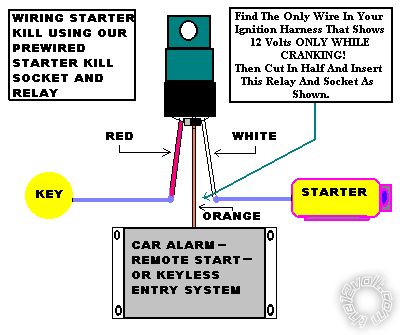
Posted By: juavos00
Date Posted: May 14, 2010 at 9:25 PM
last question.. Can I connect the H1/12 BROWN (-) wire directly to the BLACK (-) wire on the truck for the horn, without a relay?
Posted By: blanx218
Date Posted: May 17, 2010 at 12:34 AM
give it a shot. if it does work no worries. if not then you'll need a relay. as far as the starter kill, i'd imagine from the diagram that the relay socket has it configured already so 3 connections will cover it. for it to work correctly with 3 wires the red wire would have to be connected to pins 86 and 87a in the socket itself
Posted By: juavos00
Date Posted: May 21, 2010 at 11:38 PM
UPDATE: One good thing, and a big bad thing has happened. Good thing is I have everything wired in the way I think its supposed to be, and the doors lock and unlock with the factory keyfobs like it should. Also the horn works just like it should.. Now for the bad thing. There is a draw on my battery that keeps killing it about a day later. I charge it, then next day boom dead.. What can be causing this. We have metered it to be a 3-amp draw on the battery. For the relay socket, here is how the colors show: 87 - N/A
87a - white
86 - orange (diode)
85 - red (diode - band facing)
30 - red There is a bridge between the 85 and 30 pins. I guess that is where the 3 wire setup comes from.. Anyway is that setup making the draw on my system? My dad thinks its the starter, but now I am thinking this relay config has something to do with it. Please post back. Thanks
Posted By: juavos00
Date Posted: May 22, 2010 at 12:07 AM
Would this work, like you had said the relay needed to be before? 87 - N/A
87a - red
86 - orange (diode)
85 - red (diode - band facing)
30 - white Jumper wire between pins 85 and 87a.
OR should it be like this: 87 - N/A
87a - red
86 - red (diode - band facing)
85 - orange (diode)
30 - white Jumper wire between pins 86 and 87a.
|