using the dei 528t on an existing alarm?
Printed From: the12volt.com
Forum Name: Car Security and Convenience
Forum Discription: Car Alarms, Keyless Entries, Remote Starters, Immobilizer Bypasses, Sensors, Door Locks, Window Modules, Heated Mirrors, Heated Seats, etc.
URL: https://www.the12volt.com/installbay/forum_posts.asp?tid=121727
Printed Date: May 02, 2026 at 11:47 PM
Topic: using the dei 528t on an existing alarm?
Posted By: restoman
Subject: using the dei 528t on an existing alarm?
Date Posted: May 07, 2010 at 2:16 PM
Hello folks. New guy here with a question. (And please be kind. I know NOTHING about electronics.)
I have a 1969 Chevrolet Corvette that came with the optional horn alarm. This utilizes a key located on the tail panel to activate the alarm and a few relays, a flasher, a horn and a couple of door contacts. It's a really simple system. The problem is that when the doors are opened, the horn sounds FOREVER!! It's not like one of the newer alarms where they sound for 90 seconds and then reset. This one never shuts off and eventually drains the battery (and my neighbors)!
I have a friend that suggested I install a DEI 528T relay/timer and configure it so the alarm will go off for 90 seconds (or whatever I want), then automatically reset. However, when I got the relay/timer in the mail, I was shocked to see that the "instructions" (if you can call them that) are SADLY inadequate! (And that's being kind!!)
So anyway, my questions is can someone tell me how to hook this thing up to my alarm so I can keep what's left of my neighbors as friends?!
If you need more info, or a basic schematic of the existing alarm, let me know...
Thanks
Ed
Replies:
Posted By: howie ll
Date Posted: May 07, 2010 at 2:43 PM
We would need to know if the key switch switches neg or pos to feed the alarm, or how is the horn fed? Via a relay and how is it wired. The info on the 528t is pretty simple for a pro, I've even used one to make a wash-wipe!
Posted By: restoman
Date Posted: May 07, 2010 at 2:58 PM
Howie, the key switch just ties the positive side of the battery to one of the relays. I've attached a drawing showing how the system works. Let me know if you need more info.
Ed 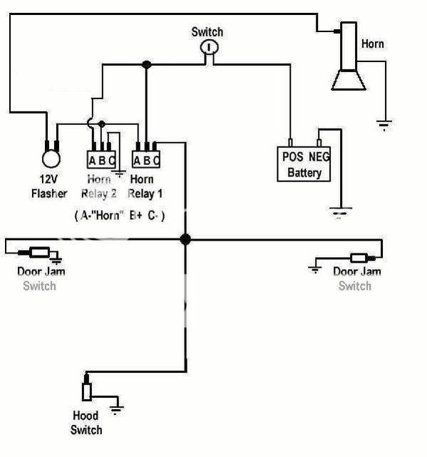
Posted By: restoman
Date Posted: May 07, 2010 at 3:27 PM
Sorry folks. The drawing I uploaded was too big, so I deleted it and uploaded a smaller one:
Posted By: howie ll
Date Posted: May 07, 2010 at 5:18 PM
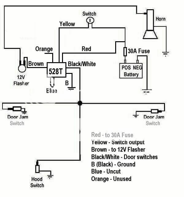
Remove the 2 relays, then join red and black on the 528 to a 30amp fuse, red and black to a good ground, from the fuse, feed the switch wire then bring the other side of the switch to yellow on the 528t. Ignore the orange and bring the brown out to the flasher unit then feed the horn from the flasher units output. Run the BLACK/ white on the 528t to your contact switches, then set the timer for say 30 secs. You could also use another relay from the flasher out put to run your lights if desired.
Posted By: lectricguy
Date Posted: May 07, 2010 at 5:20 PM
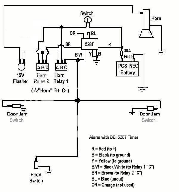
restoman- From your diagram, it appears that Horn Relay 2 latches when Horn Relay 1 triggers. I would use a 528T to connect the ground on Horn Relay 2 for the time you want the alarm to sound, and then break the ground. I would wire the 528T as follows: Red to +12V Black to Ground Disconnect Horn Relay 2 terminal C from ground Yellow to Ground Brown to Horn Relay 2 terminal C Black with Stripe to Horn relay 1 Terminal C Orange is not used. Blue loop uncut (Negative Trigger).
Theory of Operation: When the door pin is grounded (door opened) while the alarm is on, Horn Relay 1 will provide 12V to Horn Relay 2 and the flasher. At the same time, the 528T will receive a negative pulse from the door pin (from Black w/Stripe), and Brown and Yellow contacts will be connected for the timer setting time. Because Horn Relay 2 will receive Ground on Terminal C through the 528T Brown and Yellow, Horn Relay 2 will Turn on, providing power from its terminal A to Terminal B. When the 528T Brown and Yellow contacts open as the timer completes its cycle, Horn Relay 2 opens and the alarm turns off.
------------- Lectric Guy
Posted By: lectricguy
Date Posted: May 07, 2010 at 5:36 PM
There are many ways to "skin the cat". Howie's approach is also excellent, as it reduces the relays involved. I attempted to simplify the wiring you need to do. Either will work.
-------------
Lectric Guy
Posted By: restoman
Date Posted: May 07, 2010 at 7:09 PM
Thank you gentlemen! I don't have a 30 amp fuse in the fuse box, so it would have to be an in-line one coming directly from the battery, right? I wouldn't mind getting rid of a few relays, but I'm confused Howie. You said:
"Remove the 2 relays, then join red and black on the 528 to a 30amp fuse, red and black to a good ground"
You have red and black going to a 30 amp fuse AND to ground!! I don't know a lot about electronics, but I DO know you can't have both! Am I missing something here? My 528 has a solid red wire, a solid black wire, a solid orange wire, a solid brown wire, a solid yellow wire, a black wire with a white stripe and a small blue wire that comes out of the housing and then goes right back in again. Is mine different than the "norm"? A simple drawing showing what you mean would be great!
Lectric guy, your way appears to be the easiest way using the existing hardware, but I might go the other route since it removes parts that aren't really necessary with the 528. But if I get too confused, I'll go your route!!
Ed
Posted By: restoman
Date Posted: May 09, 2010 at 7:12 PM
Lectricguy, I modified my drawing per your instructions, but I'm not sure I got it right. Can you take a look and verify I have it correct?
Howie, can you give me a little more info on what I would need to do to get rid of the two relays? I like your idea better since it removes some componets, but I'm confused about the configuration.
Thanks again guys
Ed
Posted By: lectricguy
Date Posted: May 09, 2010 at 8:50 PM
You have the diagram I described correct.
For Howie's approach: Disconnect Horn Relay 1 and 2 For 528T-- Red to +12V Fused and to the input side of the switch. Yellow to the output side of the switch. Brown to the Flasher input. Black with Stripe to the Door Pin Switches. Black to Ground. Orange is not used. Blue loop uncut (Negative Trigger).
------------- Lectric Guy
Posted By: howie ll
Date Posted: May 10, 2010 at 2:26 AM
Actually, first sorry for confusing you,you're quite correct,obviously red to 12v+ and black to ground. My syntax was terrible.
Unfortunately, your second diagramme is wrong!
Where you show yellow joined to black going to ground, as lectricguy rightly says, it goes to the pos. OUTPUT side of the switch.
Posted By: lectricguy
Date Posted: May 10, 2010 at 6:07 AM
Howie- The diagram posted on 5/9 correctly depicts the application I described in an earlier post; this makes/breaks the ground for existing Horn Relay 2 to control the cycle. This was the approach using existing relays, just interrupting the latched state of Horn Relay 2. Yellow is required to be grounded in that application. Your recommendation, which is more efficient as it eliminates the 2 Horn Relays, must connect power to yellow at the switch output. As you point out, your recommended application must not tie yellow to ground. Restoman- Be extremely careful in wiring which ever application you choose. Make all the connections except the brown, and test the brown output with a test light or meter before connecting. ------------- Lectric Guy
Posted By: howie ll
Date Posted: May 10, 2010 at 6:41 AM
I'm still trying to work out why two relays were used on the original installation.
I might also have used a Velleman 100 kit rather than a 528t since it oscillates and would eliminate the flasher unit.
Posted By: restoman
Date Posted: May 10, 2010 at 8:09 PM
Okay gents. I think I have it now (NOT using the original relays). Take a look at the new "lemon fresh" drawing. Did I get it right?
Ed
Posted By: restoman
Date Posted: May 10, 2010 at 8:14 PM
Oh by the way Howie, I did a search on Velleman 100 kit and couldn't find anything. I was able to find a lot of Velleman kits, but none of them had just the 100 in them. Is there another part number for this kit? If it's not too expensive, I might go that route and get rid of even more original parts!!
Thanks again for all your help guys. I really appreciate it.
Ed
Posted By: howie ll
Date Posted: May 11, 2010 at 1:39 AM
Your diagramme is spot on, the Velleman kit was an Mk111. The problem is here in the UK the 528t trade price is about $9, the Velleman kit is the same but I've still got to build it!
Posted By: restoman
Date Posted: May 11, 2010 at 8:52 AM
Thanks again Howie. Here in the US, I found the MK111 at Frys for just under $5.00, so I might pick one up. I also found the pre-assembled version VM136 on ebay for $20.00, but $15.00 seems a bit steep just to have it already assembled. It appears to be very easy to assemble, so I'll give it a go. I'm assuming it comes with instructions??
Ed
Posted By: howie ll
Date Posted: May 11, 2010 at 10:46 AM
Yes but......  I remove the smaller pot to give me the same result as the 528t, you won't need the first transistor etc. since you are only giving it a neg pulse. Unfortunately its price here £5 against £6 ($ = x 1.5) makes it not worthwhile if you include building time.
Yes instructions are included.
Posted By: restoman
Date Posted: May 12, 2010 at 11:32 AM
Thanks again Howie. One last question... The original alarm system is really antiquated and the wiring from the battery to the key just runs under the rear tail panel, exposed to anyone that happens to look under the car!! Back in 1969, no one even heard of a car alarm, but now anyone with a pair of wire cutters can disable the thing in 2 seconds!
What I'd like to do is maybe add a wireless remote to the system and use that instead of the key switch on the rear tail panel. Would that be possible? I would leave the switch in place, giving the illusion that it's still hooked up, but instead of the key switch, use a remote key fob like that used on a normal "up to date" car alarm system. Does anyone make something that can attach to an existing system, or would it just be cheaper in the long run to install a new alarm and leave the old one "as-is" (unused)?
Ed
Posted By: howie ll
Date Posted: May 12, 2010 at 12:23 PM
Yes it's called an alarm! Doing it any other way would involve using relays which would be latched, = flat battery.
Posted By: restoman
Date Posted: May 12, 2010 at 1:46 PM
Yeah, that's what I figured. And alarms are fairly cheap, so I might just do away with the existing system and go with something built in this century!!
Ed
Posted By: restoman
Date Posted: May 22, 2010 at 12:08 AM
Okay, last (hopefully) question guys!
I'm thinking of doing away with the key switch on the rear tail panel since the only thing you have to do to defeat the system is crawl under the car with a pair of wire cutters! Everything's fully exposed, so it's VERy easy to disable the original alarm.
What I'd like to do is install a hidden switch INSIDE the car, but that would mean I would have to have some time (30 seconds or so) to be able to turn the alarm on (or off) when I get out (or back into) the car. Does the 528T also have a feature that can "pause" the circuit for a set amount of time so I can turn off the system before the horn starts sounding? Also, would I have to get another 528T to do this, or can I still use the same one to do both the "reset" function when the alarm DOES go off (so I don't kill my battery and irritate my neighbors), and the "pause" function BEFORE setting the alarm off?
Ed
Posted By: howie ll
Date Posted: May 22, 2010 at 7:35 AM
You need a second 528t set up as follows between the first and the horn and flasher wired as follows: Cut blue wire.
Pos output to siren and flasher , cut from original 528t and join to red orange and black white, brown not used, yellow to siren and flasher, black to ground.. Set time to say 15 secs, replace key switch with internal switch, will give you a 15 secs. entry and exit delay.
Posted By: restoman
Date Posted: May 22, 2010 at 12:11 PM
Thanks Howie. That's what I thought, but wanted to make sure.
Ed
|