viper 5701 door lock and unlock only
Printed From: the12volt.com
Forum Name: Car Security and Convenience
Forum Discription: Car Alarms, Keyless Entries, Remote Starters, Immobilizer Bypasses, Sensors, Door Locks, Window Modules, Heated Mirrors, Heated Seats, etc.
URL: https://www.the12volt.com/installbay/forum_posts.asp?tid=121862
Printed Date: March 21, 2026 at 11:09 AM
Topic: viper 5701 door lock and unlock only
Posted By: hunt4fun
Subject: viper 5701 door lock and unlock only
Date Posted: May 16, 2010 at 4:13 PM
I have the Viper 5701 and to start the install, I'd like just to have the power door locks work with the remote. The 12 volt + and - wires are connected to the cigarette lighter. Is this a large enough wire?
The power door lock wires (green and blue) are connected correctly and show on my voltmeter when the doors are locked and unlocked. The green door open wire is also connected. It was checked by connecting the voltmeter to a 12v + source and then connecting the negative first to a ground for verification, then to the connection. With the door closed, 12Volts, open, 0.
The ignition wire is also connected and delivers 12 volts to the pink wire.
The remote programming steps are not resulting to lock and unlock the doors.
Questions:
Do I need a larger 12V wire off of the ignition for a source of constant 12v power?
Do I have all of the wires connected correctly and is this enough to program the remote and use the door unlock and lock features?
Hunt4Fun
Replies:
Posted By: hunt4fun
Date Posted: May 16, 2010 at 4:14 PM
Sorry, forgot to include vehicle info.
1993 Ford F150 FlareSide.
Posted By: chev104275
Date Posted: May 16, 2010 at 6:49 PM
1st off use the wires at the ing switch for your power and use a clean metal spot on the chassis for ground
Remote Start
WIRE COLOR POLARITY LOCATION
Battery YELLOW (+) IGNITION SWITCH HARNESS
Ignition 1 RED / LIGHT GREEN (+) IGNITION SWITCH HARNESS
Accessory 1 GRAY / YELLOW (+) IGNITION SWITCH HARNESS
Starter 1 RED / LIGHT BLUE (+) IGNITION SWITCH HARNESS
as for door locks if you dont have factory keyless entry you will need 2 relays and 5 wire the lock wires (see the tab above marked relays)
if you do have factory keyless entry then they are just a positive triggered locks
Doorlocks/Windows
WIRE COLOR POLARITY LOCATION
Power Unlock PINK/LIGHT GREEN (REV) REVERSE POLARITY "USE DRV SW TO TEST"
(+) ON KEYLESS EQUIPPED VEHICLES
PowerLock PINK / YELLOW (REV) PASSENGER KICK PANEL
(+) ON KEYLESS EQUIPPED VEHICLES
-------------
If i Can't Install it I Don't need it Joe
Posted By: blanx218
Date Posted: May 17, 2010 at 12:13 AM
you would also want to redo the door trigger connection. the green from the 5701 is a negative input. you're connected to a positive door trigger and would need to connect the purple (+) door trigger wire from the alarm. without it your alarm wont go off when a door opens and you also wont be able to program any features without a bitwriter
Posted By: hunt4fun
Date Posted: May 17, 2010 at 9:21 AM
Thanks very much for the responses. I'll stop and get the relays and hope to install them this evening. And I'll switch over to the violet wire.
When doing the remote programming does the Valet Key have to be plugged into the control unit? If so, where?
Posted By: hunt4fun
Date Posted: May 17, 2010 at 11:20 AM
As a follow-up question, I have a separate valet key. 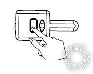
It has a connector on the front, but I have not found any way to connect it to the control unit. What am I missing?
Posted By: t&t tech
Date Posted: May 18, 2010 at 7:02 AM
Valet Key? Or switch? They are competely different! The valet switch is built in to the antenna, just plug it in where it fits!
-------------
Posted By: hunt4fun
Date Posted: May 18, 2010 at 7:54 AM
I thought switch. 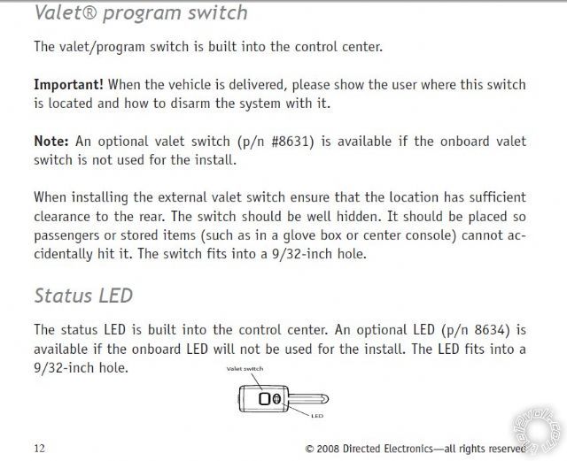
The picture is from the install manual. Does this connect to the control center by the long, slender key portion or by the electrical connector on the end?
Posted By: howie ll
Date Posted: May 18, 2010 at 11:31 AM
Should you be installing this yourself? That last post begs understanding. Of Course use the provided loom!
Posted By: hunt4fun
Date Posted: May 18, 2010 at 11:42 AM
It appears that I may be missing some of the wiring harnesses then. Nothing that I have plugs into the valet switch, but I'll double check everything this evening.
As far as doing this myself goes, considering that I do all of my own maintenance, have installed body lifts, replaced engines, driveshafts, rearends, complete brake systems end to end, rewired an entire engine that had been sitting for 5 years and was destroyed by mice, have the service manuals including the electrical diagrams for the vehicle, have worked 30 years as a software developer, built PCs from scrap parts on multiple occasions, taught PC hardware to novices both in the US and through an interpreter in Russia, Yeah, I think I'll take a shot at this. From what I can tell so far, if you can read and connect wires, your ready. But if the installation guide says to connect A to B or assumes that you have connected A to B, and you don't have B, you are at the least confused and at worse, screwed.
Posted By: blanx218
Date Posted: May 18, 2010 at 11:47 AM
the picture at the bottom of the previous post is the antenna. the cable for the antenna has at one end a long thin black plug. that is the antenna side. the other end has a similar plug but also a small white and small blue plug. these are for the LED and valet switch respectively and plug in to the color coded 2pin ports on the brain
Posted By: hunt4fun
Date Posted: May 18, 2010 at 11:54 AM
Thank you. Now I know what I'm looking for. Blanx, you should have written the instructions. You instructions are much more succinct and you have obviously deduced the issue I was having.
Thanks again.
Hunt4Fun
Posted By: blanx218
Date Posted: May 18, 2010 at 12:53 PM
it comes from dealing with DEI's ridiculous manuals for 8 years. I forced myself to memorize anything and everything I could
Posted By: howie ll
Date Posted: May 18, 2010 at 1:10 PM
I do apologise, like Blanx I've had the same situation for years with Clifford. When they merged into DEI it got even more complicated, unfortunately I assumed you would automatically know that the antenna is "remote" from the alarm, therefore there should be an interconnect lead!
Rule of thumb, if anything such as an install manual or parts are missing, send back immediately, it's returned goods and may be faulty.
Posted By: hunt4fun
Date Posted: May 18, 2010 at 9:00 PM
No problem howie.
Now for some good news. The wiring harness for the valet switch was under some tools and papers in the box. It is now attached and I hope to be doing the actual install this week and next. It will be an off and on thing depending on the weather. Putting up a shadowbox picket fence, so if it's raining, I'll be working on the alarm, otherwise, the fence until it is done.
Thanks for the help. You guys got me past the parts that I was stuck on. I bought the relays yesterday, so I think I have everything I need.
Hunt4Fun
Posted By: hunt4fun
Date Posted: June 05, 2010 at 7:32 PM
Major progress. The relays for the power door locks and the alarm work great.
I went through the process of putting the brain in automatic transmission mode. Responses from the process were as it is listed in the instructions.
I will say that the led on the antenna is not functioning. It separated itself slightly from the circuit board. I can make it come
on and blink but I have to apply some pressure.
So the responses that I am going by are the chirps from the siren. After I press the remote start, the remote buzzes and then the 7 light flashes appear.
I am rather baffled at this point. It says it is in automatic mode, but the remote start doesn't recognize it.
I do have the neutral safety switch plugged in and turned to on.
Posted By: t&t tech
Date Posted: June 06, 2010 at 11:42 AM
Have you grounded the BLACK/ white wire from the smaller auxillary connector!
-------------
Posted By: howie ll
Date Posted: June 06, 2010 at 2:32 PM
Ground the green wire then try. If found that when the purple (violet) door trigger wire wads connected on Vipers they wouldn't programme.
Posted By: hunt4fun
Date Posted: June 08, 2010 at 2:32 PM
t&t tech wrote:
Have you grounded the BLACK/ white wire from the smaller auxillary connector!
If you are referring to the Neutral Safety Switch Input, then Yes, it is grounded.
Howie, I'll ground the green wire (H1/8) this evening and see if I can put it in Automatic transmission mode.
Thanks to all!
Hunt4Fun
Posted By: hunt4fun
Date Posted: June 08, 2010 at 7:14 PM
Ok. This is my first install and I was not sure of which wires were optional and which were required. I have some wires that are not connected. Which ones are required?
Harness 1 - 4, 7, 9, 10 & 12 are not connected
Harness 3 - 2, 3, 6, 7, 8, & 9 are not connected.
The alarm and door locks work perfectly. But I cannot program anything to the computer.
Posted By: hunt4fun
Date Posted: June 11, 2010 at 5:36 PM
Any suggestions?
Posted By: t&t tech
Date Posted: June 11, 2010 at 7:06 PM
Would you mind listing the wire colours?
-------------
Posted By: hunt4fun
Date Posted: June 11, 2010 at 7:55 PM
Not at all. Here is the complete list from the install manual.
Primary harness (H1), 12-pin connector
H1/1 RED / WHITE (-) 200mA TRUNK RELEASE OUTPUT
H1/2 RED (+)12v CONSTANT INPUT
H1/3 BROWN (+) SIREN OUTPUT
H1/4 WHITE/ BROWNLIGHT FLASH -ISOLATION WIRE - PIN 87a of onboard relay
H1/5 BLACK (-) CHASSIS GROUND
H1/6 VIOLET (+) DOOR TRIGGER INPUT
H1/7 BLUE (-) TRUNK PIN/ INSTANT TRIGGER INPUT
H1/8 GREEN (-) DOOR TRIGGER INPUT
H1/9 BLACK/ WHITE (-) 200mA DOME LIGHT OUTPUT
H1/10 WHITE/ BLUE (-) REMOTE START/ TURBO TIMER ACTIVATION INPUT
H1/11 WHITE PARKING LIGHT OUTPUT
H1/12 ORANGE (-) 500mA GROUND WHEN ARMED OUTPUT
Auxiliary harness (H2), 8-pin connector
H2/1 LIGHT GREEN/ BLACK (-) 200mA FACTORY ALARM DISARM OUTPUT
H2/2 LIGHT GREEN / WHITE (-) 200mA FACTORY ALARM ARM OUTPUT
H2/3 WHITE/ VIOLET (-) 200mA AUX 1 OUTPUT
H2/4 VIOLET/BLACK (-) 200mA AUX 2 OUTPUT
H2/5 WHITE/ BLACK (-) 200mA AUX 3 OUTPUT
H2/6 LIGHT BLUE (-) 200mA 2ND UNLOCK OUTPUT
H2/7 GRAY/BLACK (-) DIESEL WAIT TO START INPUT
H2/8 BROWN / BLACK (-) 200mA HORN HONK OUTPUT
H3 Door lock harness, 3-pin connector
1 BLUE (+) LOCK (-) UNLOCK OUTPUT
2 EMPTY NOT USED
3 GREEN (-) LOCK (+) UNLOCK OUTPUT
There are three harness connections relative to remote start function, including the heavy gauge and input and output harnesses.
Heavy gauge remote start, (H3)
10-pin connector
1 PINK (+) IGNITION 1 INPUT/OUTPUT
2 RED / WHITE (30A) FUSED IGNITION 2 / FLEX RELAY INPUT 87
3 ORANGE ACCESSORY OUTPUT
4 VIOLET (+) STARTER OUTPUT (CAR SIDE OF THE STARTER KILL WIRE)
5 GREEN (+) STARTER INPUT (KEY SIDE OF THE STARTER KILL WIRE)
6 RED (+) FUSED (30A) IGNITION 1 INPUT
7 PINK/WHITE (+) IGNITION 2 / FLEX RELAY OUTPUT
8 PINK/BLACK FLEX RELAY INPUT 87A key side (if required) of FLEX RELAY
9 RED / BLACK FUSED (30A) ACCESSORY/STARTER INPUT
10 N/C N/C
Remote start input, 5-pin connector
1 BLACK/ WHITE (-) NEUTRAL SAFETY SWITCH INPUT
2 VIOLET/WHITE TACHOMETER INPUT WIRE
3 BROWN (+) BRAKE SHUTDOWN WIRE
4 GRAY N/O or N/C (-) HOOD PIN SWITCH INPUT, ZONE 6
5 BLUE/WHITE (-) 200 mA 2ND STATUS/REAR DEFOGGER
Remote start auxiliary output, 5-pin
1 PINK/WHITE (-) 200mA FLEX RELAY CONTROL OUTPUT
2 ORANGE (-) 200mA ACCESSORY OUTPUT
3 VIOLET (-) 200mA STARTER OUTPUT
4 PINK (-) 200mA IGNITION 1 OUTPUT
5 BLUE (-) 200mA STATUS OUTPUT
Posted By: renswic
Date Posted: June 12, 2010 at 6:49 AM
this may sound odd, but did you connect the little toggle switch to the brain? and make sure its on? i had these problems in my 03 taurus in tell i looked and saw that i managed to flip it off while working in the area of the switch
also on the 98 astro that i did a 5101 remote start in, it had a ton of problems starting while throwing random codes and ended up having to change the crank time and shutting off the tach mode.
though it honestly does sound like its not programing for auto trans, might be able to talk a local installer into giving up a few minuets of their time and seeing if they can get it programed for ya
Posted By: hunt4fun
Date Posted: June 12, 2010 at 3:04 PM
Yes. The switch is connect and on.
Posted By: t&t tech
Date Posted: June 12, 2010 at 7:11 PM
Mind listing what you have and don't have connected? Seeing we're trying to assist you please be as informative as possible on your install so we don't have to be labouring in our minds and we get tired and you get no replies!
-------------
Posted By: hunt4fun
Date Posted: June 12, 2010 at 9:28 PM
Primary harness (H1), 12-pin connector
H1/1 RED / WHITE (-) 200mA TRUNK RELEASE OUTPUT not connected
H1/2 RED (+)12v CONSTANT INPUT Connected to 12v in steering column
H1/3 BROWN (+) SIREN OUTPUT connected to siren
H1/4 WHITE/ BROWN LIGHT FLASH -ISOLATION WIRE - PIN 87a of onboard relay not connected
H1/5 BLACK (-) CHASSIS GROUND connected to ground
H1/6 VIOLET (+) DOOR TRIGGER INPUT connected to door "open" wire
H1/7 BLUE (-) TRUNK PIN/ INSTANT TRIGGER INPUT not connected
H1/8 GREEN (-) DOOR TRIGGER INPUT connected to ground
H1/9 BLACK/ WHITE (-) 200mA DOME LIGHT OUTPUT not connected
H1/10 WHITE/ BLUE (-) REMOTE START/ TURBO TIMER ACTIVATION INPUT not connected
H1/11 WHITE PARKING LIGHT OUTPUT connected to parking lights at the headlamp switch
H1/12 ORANGE (-) 500mA GROUND WHEN ARMED OUTPUT not connected
Auxiliary harness (H2), 8-pin connector not connected
H2/1 LIGHT GREEN/ BLACK (-) 200mA FACTORY ALARM DISARM OUTPUT
H2/2 LIGHT GREEN / WHITE (-) 200mA FACTORY ALARM ARM OUTPUT
H2/3 WHITE/ VIOLET (-) 200mA AUX 1 OUTPUT
H2/4 VIOLET/BLACK (-) 200mA AUX 2 OUTPUT
H2/5 WHITE/ BLACK (-) 200mA AUX 3 OUTPUT
H2/6 LIGHT BLUE (-) 200mA 2ND UNLOCK OUTPUT
H2/7 GRAY/BLACK (-) DIESEL WAIT TO START INPUT
H2/8 BROWN / BLACK (-) 200mA HORN HONK OUTPUT
H3 Door lock harness, 3-pin connector
1 BLUE (+) LOCK (-) UNLOCK OUTPUT connected to power door locks relay and working
2 EMPTY NOT USED
3 GREEN (-) LOCK (+) UNLOCK OUTPUT connected to power door locks relay and working
There are three harness connections relative to remote start function, including the heavy gauge and input and output harnesses.
Heavy gauge remote start, (H3)
10-pin connector
1 PINK (+) IGNITION 1 INPUT/OUTPUT connected to 12v when key is in the RUN position.
2 RED / WHITE (30A) FUSED IGNITION 2 / FLEX RELAY INPUT 87 not connected
3 ORANGE ACCESSORY OUTPUT not connected
4 VIOLET (+) STARTER OUTPUT (CAR SIDE OF THE STARTER KILL WIRE) connected to starter side of the start wire
5 GREEN (+) STARTER INPUT (KEY SIDE OF THE STARTER KILL WIRE) connected to the key side of the start wire.
6 RED (+) FUSED (30A) IGNITION 1 INPUT not connected
7 PINK/WHITE (+) IGNITION 2 / FLEX RELAY OUTPUT not connected
8 PINK/BLACK FLEX RELAY INPUT 87A key side (if required) of FLEX RELAY not connected
9 RED / BLACK FUSED (30A) ACCESSORY/STARTER INPUT not connected
10 N/C N/C
Remote start input, 5-pin connector
1 BLACK/ WHITE (-) NEUTRAL SAFETY SWITCH INPUT connected to ground
2 VIOLET/WHITE TACHOMETER INPUT WIRE connected to BLACK / YELLOW wire going to the tachometer. Verified by running and revving the engine while connected to a voltmeter.
3 BROWN (+) BRAKE SHUTDOWN WIRE connected to brake switch from the pedal
4 GRAY N/O or N/C (-) HOOD PIN SWITCH INPUT, ZONE 6 connected to ground for now.
5 BLUE/WHITE (-) 200 mA 2ND STATUS/REAR DEFOGGER not connected
Remote start auxiliary output, 5-pin not connected
1 PINK/WHITE (-) 200mA FLEX RELAY CONTROL OUTPUT
2 ORANGE (-) 200mA ACCESSORY OUTPUT
3 VIOLET (-) 200mA STARTER OUTPUT
4 PINK (-) 200mA IGNITION 1 OUTPUT planning to connect to LOCK relay
5 BLUE (-) 200mA STATUS OUTPUT
Posted By: hunt4fun
Date Posted: June 15, 2010 at 9:55 PM
Is there more information I can provide? Do I have everything connected that needs to be?
Posted By: smokeman1
Date Posted: June 15, 2010 at 10:13 PM
I don't see where anything on the H3 Heavy gauge Harness is connected to a constant 12 volt source. And the H3/1 should be connected to the ignition wire. And why don't you have the orange wire for accessory hooked up?
-------------
When all else fails, Read the Instructions
Support the12volt.com Make a Donation
Posted By: hunt4fun
Date Posted: June 15, 2010 at 10:54 PM
smokeman1 wrote:
I don't see where anything on the H3 Heavy gauge Harness is connected to a constant 12 volt source. And the H3/1 should be connected to the ignition wire. And why don't you have the orange wire for accessory hooked up?
Ok. So I need to connect both 1, 6, and 9 to a constant 12V source? And the ORANGE (#3) should be connected to the same wire that shows 12 volts when the key is in the accessory position?
Posted By: smokeman1
Date Posted: June 16, 2010 at 12:51 PM
I am a DIY installer not a Professional, and not wanting to offend you, but, Do you have the Installation Guide for this remote starter? If not, it is available in the download section of this web site.
If you look at a posting to you from chev104275 on May 16th, the wires you need to check, verify, (with a DMM) and use for the heavy gauge harness were in that posting.
 |
Battery |
|
YELLOW |
|
(+) |
|
IGNITION SWITCH HARNESS |
|
|
|
Ignition 1 |
|
RED / LIGHT GREEN |
|
(+) |
|
IGNITION SWITCH HARNESS |
|
|
|
Accessory 1 |
|
GRAY / YELLOW |
|
(+) |
|
IGNITION SWITCH HARNESS |
|
|
|
Starter 1 |
|
RED / LIGHT BLUE |
|
(+) |
|
IGNITION SWITCH HARNESS |
On your Heavy Gauge Harness,
H3/1 should go to the RED / LIGHT GREEN
H3/2 not used---H3/7 Not Used-----H3/8 Not Used
H3/3 should go to the GRAY / YELLOW
H3/4 and H3/5, you seem to have those figured out ( to the RED / LIGHT BLUE)
H3/6 and H3/9 should go to YELLOW (Constant 12 volt source)
AND SOLDER THOSE CONNECTIONS!! Good Luck. Hope this guides you to a finished install.
------------- When all else fails, Read the Instructions
Support the12volt.com Make a Donation
Posted By: hunt4fun
Date Posted: June 16, 2010 at 1:35 PM
Damn, I wish I had looked back through the post. That's what happens when you try and do a project and can only work on it once a week. No constant flow of brain power. I'm sure that's what I need to verify. It looks like one trip under the steering column and I should be there.
Thanks for pointing out the error of my ways. Everyone has stress, but mine has been extremely high in the last couple of weeks. I won't bore anyone with the details of that. This is not a "counseling" forum. :)
Thanks again for the redirect. Hopefully, I'll get it going this evening. Have a blessed day.
Hunt4Fun
Posted By: hunt4fun
Date Posted: June 19, 2010 at 6:11 PM
I wanted to post a thank you to everyone. I appreciate both your wisdom and patience. The alarm and power door locks work great. When programming for Automatic mode, I get all of the response chirps as expected, but press Remote start and "BUZZ" and then the 7 light flash (still in Manual Mode). I went back and checked my connections and soldered everything together. What I have works great. I'm not sure that there is anything I can do besides take it to a professional and have him look it over.
Thanks again,
Hunt4Fun
Posted By: bsbdoa
Date Posted: June 20, 2010 at 4:14 PM
hunt4fun wrote:
Primary harness (H1), 12-pin connector
H1/1 RED / WHITE (-) 200mA TRUNK RELEASE OUTPUT not connected
H1/2 RED (+)12v CONSTANT INPUT Connected to 12v in steering column
H1/3 BROWN (+) SIREN OUTPUT connected to siren
H1/4 WHITE/ BROWN LIGHT FLASH -ISOLATION WIRE - PIN 87a of onboard relay not connected
H1/5 BLACK (-) CHASSIS GROUND connected to ground
H1/6 VIOLET (+) DOOR TRIGGER INPUT connected to door "open" wire
H1/7 BLUE (-) TRUNK PIN/ INSTANT TRIGGER INPUT not connected
H1/8 GREEN (-) DOOR TRIGGER INPUT connected to ground [u][i[] remove this, if you are using a positive trigger you do not need this wire at all.[/u][/i]
H1/9 BLACK/ WHITE (-) 200mA DOME LIGHT OUTPUT not connected
H1/10 WHITE/ BLUE (-) REMOTE START/ TURBO TIMER ACTIVATION INPUT not connected
H1/11 WHITE PARKING LIGHT OUTPUT connected to parking lights at the headlamp switch
H1/12 ORANGE (-) 500mA GROUND WHEN ARMED OUTPUT not connected
Auxiliary harness (H2), 8-pin connector not connected
H2/1 LIGHT GREEN/ BLACK (-) 200mA FACTORY ALARM DISARM OUTPUT
H2/2 LIGHT GREEN / WHITE (-) 200mA FACTORY ALARM ARM OUTPUT
H2/3 WHITE/ VIOLET (-) 200mA AUX 1 OUTPUT
H2/4 VIOLET/BLACK (-) 200mA AUX 2 OUTPUT
H2/5 WHITE/ BLACK (-) 200mA AUX 3 OUTPUT
H2/6 LIGHT BLUE (-) 200mA 2ND UNLOCK OUTPUT
H2/7 GRAY/BLACK (-) DIESEL WAIT TO START INPUT
H2/8 BROWN / BLACK (-) 200mA HORN HONK OUTPUT
H3 Door lock harness, 3-pin connector
1 BLUE (+) LOCK (-) UNLOCK OUTPUT connected to power door locks relay and working
2 EMPTY NOT USED
3 GREEN (-) LOCK (+) UNLOCK OUTPUT connected to power door locks relay and working
There are three harness connections relative to remote start function, including the heavy gauge and input and output harnesses.
Heavy gauge remote start, (H3)
10-pin connector
1 PINK (+) IGNITION 1 INPUT/OUTPUT connected to 12v when key is in the RUN position.
2 RED / WHITE (30A) FUSED IGNITION 2 / FLEX RELAY INPUT 87 not connected
3 ORANGE ACCESSORY OUTPUT not connected [u][i]this needs to be connected if you want your fan/ climate controls to function during remote start. it is grey / YELLOW at the ignition switch[/i][/u]
4 VIOLET (+) STARTER OUTPUT (CAR SIDE OF THE STARTER KILL WIRE) connected to starter side of the start wire
5 GREEN (+) STARTER INPUT (KEY SIDE OF THE STARTER KILL WIRE) connected to the key side of the start wire.
6 RED (+) FUSED (30A) IGNITION 1 INPUT not connected [u][i]this needs to be connected to 12v constant yellow at ign switch[/i][/u]
7 PINK/WHITE (+) IGNITION 2 / FLEX RELAY OUTPUT not connected
8 PINK/BLACK FLEX RELAY INPUT 87A key side (if required) of FLEX RELAY not connected
9 RED / BLACK FUSED (30A) ACCESSORY/STARTER INPUT not connected [u][i]this needs to be connected to 12v constant[/i][/u]
10 N/C N/C
Remote start input, 5-pin connector
1 BLACK/ WHITE (-) NEUTRAL SAFETY SWITCH INPUT connected to ground
2 VIOLET/WHITE TACHOMETER INPUT WIRE connected to BLACK / YELLOW wire going to the tachometer. Verified by running and revving the engine while connected to a voltmeter.
3 BROWN (+) BRAKE SHUTDOWN WIRE connected to brake switch from the pedal
4 GRAY N/O or N/C (-) HOOD PIN SWITCH INPUT, ZONE 6 connected to ground for now. [u][i]while this is grounded the starter will not function as it defaults to n/o and by grounding it your starter thinks the hood is open[/i][/u]
5 BLUE/WHITE (-) 200 mA 2ND STATUS/REAR DEFOGGER not connected
Remote start auxiliary output, 5-pin not connected
1 PINK/WHITE (-) 200mA FLEX RELAY CONTROL OUTPUT
2 ORANGE (-) 200mA ACCESSORY OUTPUT
3 VIOLET (-) 200mA STARTER OUTPUT
4 PINK (-) 200mA IGNITION 1 OUTPUT planning to connect to LOCK relay [u][i]do not do this, in essance it would be the same as holding the lock button any time the car is running. if you want to have the car relock after starting use the (-) starter output otherwise turn on ignition controlled locks in the feature menu which depending on programing will lock the door when the car is started and unlock when you turn it off with the key[/i][/u]
5 BLUE (-) 200mA STATUS OUTPUT
btw I am a professional installer and have done thousands of remote starters, someone like myself should be able to do this job in about an hour or two; making it a great truck to learn on. but just think logically about it. the starter is basically a bunch of relays with a controller. the red on the heavy gauge harness are the input for a relay and the purple, orange and pink are outputs. and please solder and securely tape your connections no butt connectors or t-taps they are crap.
Posted By: bsbdoa
Date Posted: June 20, 2010 at 4:18 PM
i forgot to mention but if you do use the (-) start to trigger the locks on remote start be sure to diode issolate it otherwise your truck will crank every time you lock the doors
Posted By: hunt4fun
Date Posted: June 20, 2010 at 7:44 PM
bsbdoa, thanks for the info. I have not hooked up anything to automatically lock the doors since I found that it is a programming option. I disconnected the hood input that was grounded. Current status is as follows:
Primary harness (H1), 12-pin connector
H1/1 RED / WHITE (-) 200mA TRUNK RELEASE OUTPUT not connected
H1/2 RED (+)12v CONSTANT INPUT Connected to 12v in steering column
H1/3 BROWN (+) SIREN OUTPUT connected to siren
H1/4 WHITE/ BROWN LIGHT FLASH -ISOLATION WIRE - PIN 87a of onboard relay not connected
H1/5 BLACK (-) CHASSIS GROUND connected to ground
H1/6 VIOLET (+) DOOR TRIGGER INPUT connected to door "open" wire
H1/7 BLUE (-) TRUNK PIN/ INSTANT TRIGGER INPUT not connected
H1/8 GREEN (-) DOOR TRIGGER INPUT connected to ground Have not removed this yet. Next step.
H1/9 BLACK/ WHITE (-) 200mA DOME LIGHT OUTPUT not connected
H1/10 WHITE/ BLUE (-) REMOTE START/ TURBO TIMER ACTIVATION INPUT not connected
H1/11 WHITE PARKING LIGHT OUTPUT connected to parking lights at the headlamp switch
H1/12 ORANGE (-) 500mA GROUND WHEN ARMED OUTPUT not connected
Auxiliary harness (H2), 8-pin connector not connected AND not plugged into brain
H2/1 LIGHT GREEN/ BLACK (-) 200mA FACTORY ALARM DISARM OUTPUT
H2/2 LIGHT GREEN / WHITE (-) 200mA FACTORY ALARM ARM OUTPUT
H2/3 WHITE/ VIOLET (-) 200mA AUX 1 OUTPUT
H2/4 VIOLET/BLACK (-) 200mA AUX 2 OUTPUT
H2/5 WHITE/ BLACK (-) 200mA AUX 3 OUTPUT
H2/6 LIGHT BLUE (-) 200mA 2ND UNLOCK OUTPUT
H2/7 GRAY/BLACK (-) DIESEL WAIT TO START INPUT
H2/8 BROWN / BLACK (-) 200mA HORN HONK OUTPUT
H3 Door lock harness, 3-pin connector
1 BLUE (+) LOCK (-) UNLOCK OUTPUT connected to power door locks relay and working
2 EMPTY NOT USED
3 GREEN (-) LOCK (+) UNLOCK OUTPUT connected to power door locks relay and working
There are three harness connections relative to remote start function, including the heavy gauge and input and output harnesses.
Heavy gauge remote start, (H3)
10-pin connector
1 PINK (+) IGNITION 1 INPUT/OUTPUT connected to 12v when key is in the RUN position.
2 RED / WHITE (30A) FUSED IGNITION 2 / FLEX RELAY INPUT 87 not connected
3 ORANGE ACCESSORY OUTPUT Connected to 12Volt accessory
4 VIOLET (+) STARTER OUTPUT (CAR SIDE OF THE STARTER KILL WIRE) connected to starter side of the start wire
5 GREEN (+) STARTER INPUT (KEY SIDE OF THE STARTER KILL WIRE) connected to the key side of the start wire.
6 RED (+) FUSED (30A) IGNITION 1 INPUTconnected to 12Volt constant
7 PINK/WHITE (+) IGNITION 2 / FLEX RELAY OUTPUT not connected
8 PINK/BLACK FLEX RELAY INPUT 87A key side (if required) of FLEX RELAY not connected
9 RED / BLACK FUSED (30A) ACCESSORY/STARTER INPUT connected to 12v constant
10 N/C N/C
Remote start input, 5-pin connector
1 BLACK/ WHITE (-) NEUTRAL SAFETY SWITCH INPUT connected to ground
2 VIOLET/WHITE TACHOMETER INPUT WIRE connected to BLACK / YELLOW wire going to the tachometer. Verified by running and revving the engine while connected to a voltmeter.
3 BROWN (+) BRAKE SHUTDOWN WIRE connected to brake switch from the pedal
4 GRAY N/O or N/C (-) HOOD PIN SWITCH INPUT, ZONE 6 disconnected from ground
5 BLUE/WHITE (-) 200 mA 2ND STATUS/REAR DEFOGGER not connected
Remote start auxiliary output, 5-pin not connected AND not plugged into brain
1 PINK/WHITE (-) 200mA FLEX RELAY CONTROL OUTPUT
2 ORANGE (-) 200mA ACCESSORY OUTPUT
3 VIOLET (-) 200mA STARTER OUTPUT
4 PINK (-) 200mA IGNITION 1 OUTPUT planning to connect to LOCK relay
5 BLUE (-) 200mA STATUS OUTPUT
Posted By: hunt4fun
Date Posted: June 20, 2010 at 8:17 PM
Forgot to mention that the system will not accept any programming. I've tried to set it to Automatic mode, Manual and then Automatic Mode, automatic door lock with ignition. No luck. I'll check who are the pros in the area tomorrow.
Posted By: hunt4fun
Date Posted: June 21, 2010 at 8:27 PM
Here is the rest of the story. The issue with the remote start was a Ford issue, not a Viper one. There are two wires in the service manual that are HOT when the key is in the RUN position. Only 1 of them is also HOT in the START position. I switched over the PINK wire to the wire that is HOT in both positions and it works.
I stopped on my way home before this at a professional shop. The guy was able to program the unit for Automatic transmission and also programmed it for LOCK ONLY when the ignition is turned to RUN. My truck unlocks the door when you open it from the inside so I wanted the locks to LOCK ONLY. That is not happening yet, but I'll research that with a few searches. Regardless of what happens with that, I'm very happy that the unit is fully functional.
Thanks to all who contributed.
Posted By: hunt4fun
Date Posted: June 22, 2010 at 7:24 PM
howie ll wrote:
Ground the green wire then try. If found that when the purple (violet) door trigger wire wads connected on Vipers they wouldn't programme.
Just as a follow-up, grounding the green wire did prevent being able to program the unit except with a Bitwriter. Once we clipped that wire out of the ground, the system accepted the commands to LOCK ONLY on ignition.
So, it has taken 3-4 weeks off and on, $65 at the professional installation center, and more hours of work than I ever dreamed. But, the benefits outweigh the negatives. I understand everything about how my system works and if there is ever a problem, I'll have some idea how to correct it. I've "met" some nice folks who tried hard to help me here on 12volt. And I met a professional installer that is both knowledgeable and friendly.
So all in all, this job is about 50% knowledge and 50% pure determination.
Hunt4Fun
|