They are a microswitch inside the actuator. Black goes to constant ground, the other two will go to ground depending on the actuator's position. Mounted in the driver's door, the door key turning a lock will therefore move the actuator and change which wire goes to ground thus activating a dedicated central locking relay and operating the other locks. Also known as masters.
Howie thanks for the explanation .. so what i want to do is to create a 2 stage unlock from just one unlock (-) wire from the alarm for my car.
I have created a diagram in paint ( i wish i knew a program to do it faster and easier - please recommend one).
please look at it and tell me if this could actually help me achieve my goal . looking at it for me it seemed possible but only if i understood from your explanations how the 5 wire actuators work.
I know I can use an AUX output but i like to challenge myself.
If this diagram is correct I would like to know if i will have to use diodes and where and how to put them.
Of course this works only for aftermarket actuators and that's what i will use in my car.
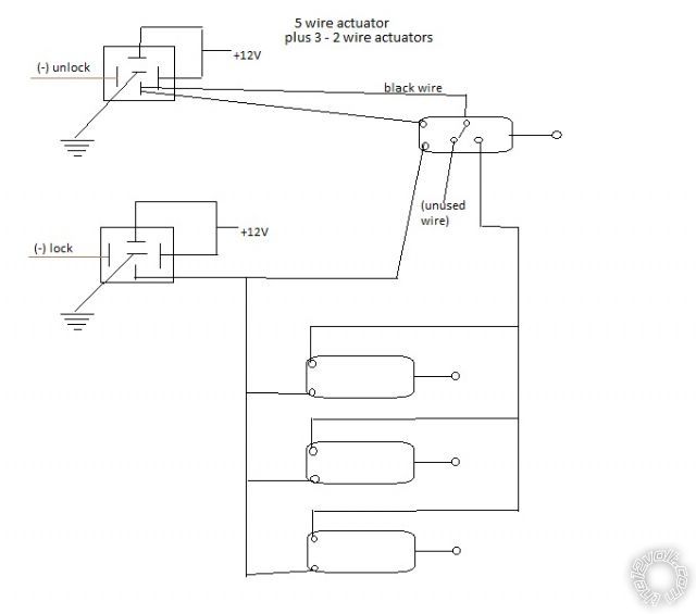
Completely wrong.
It's this with three relays required.
Relay 1 lock all.
Alarm lock to 85.
12v+ 25/30amps to 87 and 87 on on all 3 relays
Ground to 87a all 3 relays
30 to all motor lock wires (to green if mounted vertically and actuator is pulling down to lock)
Relay 2 unlock driver's door.
Unlock wire from alarm to 85, 30 to blue motor unlock wire (see above, blue) in driver's door other terminals as above.
Relay 3 unlock other doors.
2nd. Unlock or aux to 85, 30 to blue in all other doors.
Ignore all but the green and blue motor wires on the actuators.
OK so howie you think that the only way to do that is with a 2nd unlock wire (which i dont have on my alarm) or with AUx output wire(this one i have).
now simply curiosity ... howie or anybody else that might check my diagram , can u tell me what is wrong in the logic of it ? i have tried it in my head and paper many times and for me it seemed possible but if somebody can explain i will be very thankful.
I do understand that it is about physics and electronics that i do not know so this can be more of a lesson to me too.
in any case thank you for all your help.
Try it in the flesh and it won't work. The black wire from the output of the unlock relay, it will simply pull the slaves at the same time*. You won't be able to differentiate, hence 3 relays.
*That is if it doesn't burn out carrying the more or less 15 amps of the other 3 motors.
ok ... i understand ... thank you.
auxiliary output it is then.