2010 dodge ram alarm
Printed From: the12volt.com
Forum Name: Car Security and Convenience
Forum Discription: Car Alarms, Keyless Entries, Remote Starters, Immobilizer Bypasses, Sensors, Door Locks, Window Modules, Heated Mirrors, Heated Seats, etc.
URL: https://www.the12volt.com/installbay/forum_posts.asp?tid=122536
Printed Date: April 09, 2026 at 12:32 AM
Topic: 2010 dodge ram alarm
Posted By: johndoby
Subject: 2010 dodge ram alarm
Date Posted: July 04, 2010 at 10:26 PM
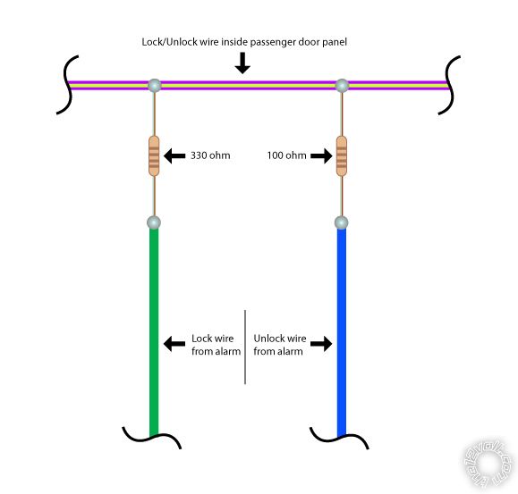
So I spent the better part of the evening installing a Python alarm system. I did my research and found that I needed a 330 ohm resistor for my my lock lead and a 100 for my unlock lead. I had both of these and soldered them in. The first time I did it, I soldered them both at the same splice point, tying them in to the PURPLE / green wire in the passenger side door. When I tested everything out, the doors would not lock/unlock from the fob, or from the buttons on the passenger door. I unsoldered the connection and tried soldering them individually into the wire about 1.5" inches from each other. I thought I fixed it because when I plugged the harness into the brain of my alarm system, the door unlocked. Now the door will lock/unlock using the door controls but I still haven't gotten them to work using the fob.
Also, there were have been contradicting statements about the resistor to use for the parking light wire. One person said that it requires a 1.46k ohm resistor and another said that it requires a 3k resistor. I didn't a 1.46k so I figured I'd try the 3k. It didn't work. That also means that nothing that I have soldered in a resistor for has worked and therefore could be a problem with my method in that respect. I would appreciate any help you guys can give.
Thanks,
John
Replies:
Posted By: tedmond
Date Posted: July 05, 2010 at 5:38 AM
unlock - 100ohm
lock - 330ohm
you will need to go into the passsenger door for it to work. Connect to the PURPLE / LIGHT GREEN (-)
Parking lights -1000ohm WHITE (-) headlight switch, black 10 pin plug, pin 1 ------------- Ted
2nd Year Tier 1 Medical School
Still installing as a hobby...pays for groceries
Compustar Expert
Posted By: johndoby
Date Posted: July 05, 2010 at 8:08 AM
tedmond wrote:
unlock - 100ohm
lock - 330ohm
you will need to go into the passsenger door for it to work. Connect to the PURPLE / LIGHT GREEN (-)
This is exactly what I used and the door locks aren't working from the keyfob. I guess I need to just test everything with my multimeter.
I'll try the 1000 ohm resistor for the parking lights...that is the third resistor value I've seen for the same application. Hopefully it will work.
Posted By: topinstaller200
Date Posted: July 05, 2010 at 11:49 AM
For parking lights just use + to TIPM under hood
Posted By: johndoby
Date Posted: July 06, 2010 at 9:58 AM
This is the way I have it wired currently, and the locks do not work from the keyfob. They still operate using the door switch. Any ideas?
Posted By: johndoby
Date Posted: July 06, 2010 at 10:07 AM
This may also be helpful. If the battery is connected, and the door lock/unlock harness to the alarm control unit is unplugged, then I plug it in, the doors unlock once by themselves. Then there is no lock/unlock function from the keyfob.
Posted By: 91stt
Date Posted: July 06, 2010 at 2:05 PM
do the lock and unlock wires from the alarm flop from neg to pos and vice versa, if it does you will need to install diodes with the bands towards to alarm or you can use relays for ground.
-------------
This information is provided only as a reference.
All circuits should be verified with a digital multi-meter prior to making any connections.
Posted By: johndoby
Date Posted: July 07, 2010 at 1:25 PM
91stt] wrote:
do the lock and unlock wires from the alarm flop from neg to pos and vice versa, if it does you will need to install diodes with the bands towards to alarm or you can use relays for ground.
How can I test this with a digital multimeter?
Posted By: johndoby
Date Posted: July 07, 2010 at 1:48 PM
Nevermind, I just read this in the manual...
GREEN WIRE: (-)Lock, (+)Unlock
BLUE WIRE: (-)Unlock (+)Lock
So, by having them wired, I am getting a (+) signal to one wire or the other each time I press the button...and by installing diodes in the path of both wires, I will be blocking that (+) signal and allowing only the (-) signal to pass.
Is this correct, or am I completely off base?
Posted By: 91stt
Date Posted: July 07, 2010 at 3:25 PM
That is correct
The flip flop door lock wires can cause a lot of inconsistent results without diodes
-------------
This information is provided only as a reference.
All circuits should be verified with a digital multi-meter prior to making any connections.
Posted By: johndoby
Date Posted: July 08, 2010 at 10:39 AM
So I installed the diodes between the resistors and the alarm, with the band facing the alarm, and it still didn't work. In this configuration, the passenger door lock switch also ceased to function.
As far as the parking lights, I installed the 1000 ohm diode and it works great.
|