wiring lock switch on existing alarm sys.
Printed From: the12volt.com
Forum Name: Car Security and Convenience
Forum Discription: Car Alarms, Keyless Entries, Remote Starters, Immobilizer Bypasses, Sensors, Door Locks, Window Modules, Heated Mirrors, Heated Seats, etc.
URL: https://www.the12volt.com/installbay/forum_posts.asp?tid=123537
Printed Date: May 01, 2026 at 7:13 AM
Topic: wiring lock switch on existing alarm sys.
Posted By: saturnsl2
Subject: wiring lock switch on existing alarm sys.
Date Posted: September 16, 2010 at 5:11 PM
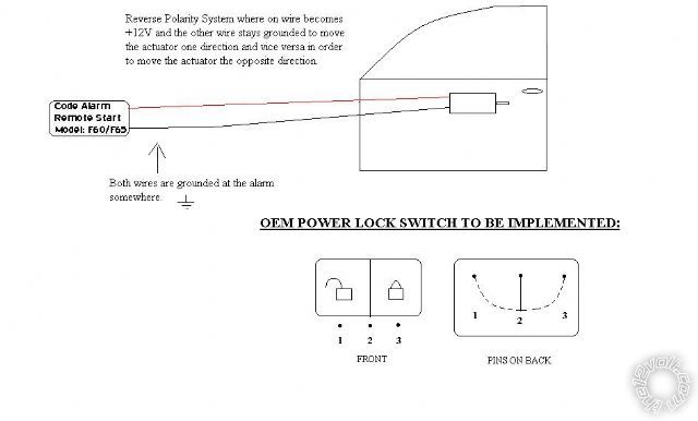
Hello guys, I am trying to install the OEM power locks on my 01 Saturn Sl2. It has aftermarket alarm/starter with aftermarket actuators. Everything was manual before. The current alarm locks all doors and unlocks all doors at the same time. I have included a picture with a drawing of what I need with an explanation and the type of current system.
Replies:
Posted By: t&t tech
Date Posted: September 16, 2010 at 6:31 PM
Ground the centre pin and each pin 1 and 3 go to a trigger wire respectively.
Posted By: saturnsl2
Date Posted: September 17, 2010 at 4:43 PM
That would not work because there would not be a potential difference anywhere so the actuators would not move. Or am I missing something?
The wires that come from the alarm to the actuators are grounded and a single wire becomes +12v when the button on the remote is pressed but when no button on the remote is pressed, both wires remain grounded on the alarm.
I am planning on doing this, this weekend but I cant figure out how to wire this. Thanks in advance!!!
Posted By: JWorm
Date Posted: September 17, 2010 at 7:02 PM
t&t tech is right, but let me elaborate.
I'll assume your code alarm does not have internal door lock relays. If it does let us know, because it will change things.
You have two relays installed for the door locks currently. They are wired as follows:
Relay 1 - lock relay
86 and 87 - constant 12v
87a - ground
30 - one wire of door lock motor
85 - lock (-) trigger from alarm
Relay 2 - unlock relay
86 and 87 - constant 12v
87a - ground
30 - one wire of door lock motor
85 - unlock (-) trigger from alarm
The relays work as follows:
You hit unlock, and a ground pulse is sent from the alarm to 85 of the unlock relay activating the relay. 87 and 30 briefly connect together throwing (+) 12volts to the unlock side of the doorlock motor. The other relay still has 87a and 30 connected providing a ground to the other wire going to the doorlock motor. There is a "potential difference" at the doorlock motor, and it moves in one direction. When you hit lock...the reverse happens.
You just need to have the door lock switch do the same thing as the alarm, which is to send a (-) trigger to 85 of the correct relay when you hit the switch on the door.
Wire the center pin to ground (probably '2'), the "unlock" pin (probably '1') to 85 of the unlock relay, and the "lock" pin (probably '3') to 85 of the lock relay.
Posted By: saturnsl2
Date Posted: September 17, 2010 at 7:34 PM
The Alarm does have internal relays.
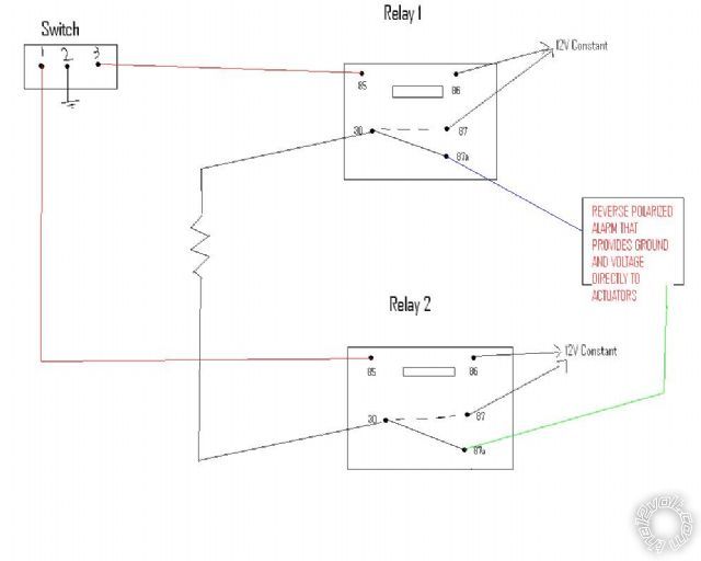
The Alarms provides the ground and the 12voltage to the actuators. So the cables go from alarm to actuators directly!!The alarm always has the two legs grounded. Then one becomes energized depending on which button on the remote is pressed. I came with something up though, can you guys check if it is right?
I am a mechanical engineer so I had to draw the relays how they physically worked since I have not memorized the pin schematics yet so please bare with me!!!haha. Thanks in advance!!!
Posted By: howie ll
Date Posted: September 18, 2010 at 11:57 AM
Then the switch you've shown will need relays to be wired in parallel with your lock outputs from the alarm, alternatively convert your alarm outputs t to neg, bring them up to your switch then to the relays, 87a is grounded.
-------------
Amateurs assume, don't test and have problems; pros test first. I am not a free install service.
Read the installation manual, do a search here or online for your vehicle wiring before posting.
Posted By: saturnsl2
Date Posted: September 18, 2010 at 10:13 PM
The circuit that I drew worked with no problems. Thanks for the help.
Posted By: t&t tech
Date Posted: September 19, 2010 at 3:32 PM
But you've shown external relays no inernal so yes that diagram will work it's what we said from the beginning.
|