2007 gmc acadia remote start
Printed From: the12volt.com
Forum Name: Car Security and Convenience
Forum Discription: Car Alarms, Keyless Entries, Remote Starters, Immobilizer Bypasses, Sensors, Door Locks, Window Modules, Heated Mirrors, Heated Seats, etc.
URL: https://www.the12volt.com/installbay/forum_posts.asp?tid=123582
Printed Date: May 02, 2026 at 4:00 AM
Topic: 2007 gmc acadia remote start
Posted By: maxxrpm
Subject: 2007 gmc acadia remote start
Date Posted: September 19, 2010 at 12:32 PM
Hi guys, I have a HIH cx2300 series remote start. I tried installing it on my 2007 acaida yesterday. I am having some issues with the wiring and connecting it to the bypass module PKUCG2X. The RS attemps to start by i get an error on the dash "Service Theft Deterrent System" I tried moving ot another wire on the dash thinking i may be on the wrong data wire but still the same. The bypass module tells me to connect a wire to (-) to ground when running output. Not sure which wire this is on the RS unit. Is there a way i can test for this wire. Also is it really important or necessary to install the resistors on the starter and accessory wire. Also do i need to connect the Factory Alarm Disarm wire. Thanks.
------------- Jamie Squire
Replies:
Posted By: kreg357
Date Posted: September 19, 2010 at 8:50 PM
I am unable to find the install guide for your CX2300 remote start. However, there should be an output wire with a label / name like GWR, Ground When Running, (-) Status Output, (-) 2nd Status, (-) Ignition3 Output, Negative Out when running, etc This wire should show a ground when the remote start goes active ( a second or two before the Ignition wire goes to +12 volts ). This wire is connected to the bypass Brown GWR Status wire.
Follow the PKU CG2X install guide for Install Type D pages 7 and 8. You will need the relay and resistors specified. ( See the note on Page 7 about the Resistor Code wire for testing with a Digital Multi Meter and computer codes ) The Data wire should be White. If the CX2300 does not supply 2 Accessory outputs, you will need more relays for the ACC2 connection.
See Section C on Page 8 for bypass programming. ------------- Soldering is fun!
Posted By: maxxrpm
Date Posted: September 20, 2010 at 8:39 AM
Hi.. THANKS. I have a 2nd ign wire but know 2nd Acc wire. How do i go about hooking this wire in and to which one does it connect to the Vehicle. Again THANKS
-------------
Jamie Squire
Posted By: maxxrpm
Date Posted: September 20, 2010 at 8:48 AM
Also with this bypass module it says to loop at least 3 or 5 loops and do not put on metal surface. Well this thing comes with a loop about 2" and the ign is about 1.5" diameter so it makes it impossible to put 3 or 5 loops and the ignition is metal. What do i do here, do i just put the loop wire over the outer ring of the ignition and take up the slack with a tie wrap or something?
-------------
Jamie Squire
Posted By: kreg357
Date Posted: September 20, 2010 at 11:41 AM
For the extra Accessory circuit, use this Install guide as a reference: https://www.readyremote.com/pdf/manuals/24921.pdf On page 18 there is a nice diagram of the wiring for the extra relays needed to provide the extra accessory output. You will need two 30/40A SPDT relays, two fuse holders & fuses, etc.
The antenna loop should be a long black wire, about 24 inches. It gets wrapped around the ingition cylinder in the location shown. The "don't put on metal surface" applies to the PKUCG2X module itself.
------------- Soldering is fun!
Posted By: maxxrpm
Date Posted: September 20, 2010 at 1:25 PM
Yes the wire is 24" long but the loop om the end makes it impossible to wrap 3 or 5 times. 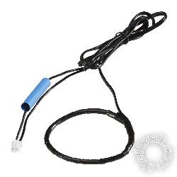
Posted By: kreg357
Date Posted: September 20, 2010 at 2:05 PM
Ahhh, you have one with the preformed loop. It already has the 3 - 5 loops in it. If the loop is too big, use a tie wrap to bunch / fold up the excess and secure it in the proper place at the same time. Hot glue gun works pretty well to tack it in place.
-------------
Soldering is fun!
Posted By: maxxrpm
Date Posted: September 20, 2010 at 2:17 PM
Thanks Bro. I will let you know how i make out after i gets some resistors. Thanks again
-------------
Jamie Squire
Posted By: maxxrpm
Date Posted: September 20, 2010 at 2:19 PM
Oh one more question. Should the antenna wire turn with the ignition or should the wire be secured and the ignition turn inside the wire....
-------------
Jamie Squire
Posted By: kreg357
Date Posted: September 20, 2010 at 2:39 PM
The modules antenna loop should be placed on the key side on the ignition cylinders' antenna. The steering column shroud on some cars is right up against it. It should be mounted securely and will not move or be too close to the inner part of the key cylinder that turns with the key. When everything is put back together it should not be visable. As a reference, take a look at the illustration on page 4 of the 556UW Install Guide. Here is a link : https://www.xpresskit.com/product.aspx?productid=44------------- Soldering is fun!
Posted By: kreg357
Date Posted: September 20, 2010 at 2:47 PM
The CX2300 Ignition 2 Output wire is not used on your car. Just insulate it.
The Accessory 2 circuit ( using the extra relays, fuses, etc ) is required for your car along with those specific resistor values. ------------- Soldering is fun!
Posted By: jim hunter
Date Posted: September 24, 2010 at 12:59 AM
these vehicles are super easy to do. just get a blank key from howard keys or the like a universal ypass like an astcbm(audiovox) or 556u(d.e.i.) or tbk--- (express kits) install remote start using only pink(ign) and brown(acc) at ig switch, ( do not need relays and resistors for start 2nd accwire, brake is yellow in the bcm, pk lites are brn/white(neg) at the switch or in the bcm,12v heavy RED / white or RED / blk in left kick, gorund in left kick, no tach required, lock and unlock are pink/blk org/blk at the bcm, after wiring up unit, test remote start with your existing key in the cylinde( not turned on) to verify all connections, then shut down remote start, turn existing key on for about 5 sec(until lock light in cluster goes out) remove key place balnk key in ing cycl and remote start vehicle( this will program new blank key transponder)after car starts, put key in the universal bypass and test then button her up done!
Posted By: maxxrpm
Date Posted: September 24, 2010 at 10:13 AM
So the 556 works with passkey 3?? ------------- Jamie Squire
Posted By: jim hunter
Date Posted: September 25, 2010 at 10:59 AM
you have to use a circle plus key, if you get thru howard keys its part 16261 there like 9.95 plus shipping and i have never used the resistors on start/2nd ign wire and have never had a problem all it will do is store a non threatening code in computer for improper key sequence,
Posted By: maxxrpm
Date Posted: September 28, 2010 at 6:05 PM
What wires are you using for start wires (vehicle side). Also when the remote start module attemps to start shouldn't i have power on the purple wire. i test this wire and when the remote start attemps to start i have 0 Volts on that wire and then when the module kicks out i get 12 V for a split second. I have no crank. Any thoughts...
-------------
Jamie Squire
Posted By: maxxrpm
Date Posted: September 28, 2010 at 8:18 PM
ok. so i programm the crank time. Now the module attemps to start and at the end of the cycle the purple crank wire powers for 2 sec but vehicle still does not crank..
-------------
Jamie Squire
Posted By: maxxrpm
Date Posted: September 28, 2010 at 9:58 PM
so i have crank but no start. unit cranks, brief start and then shuts off. both with key in and key out of ign. here is what i have...
12 Volt power.. RED / WHITE
IGN....PINK
ACC....BROWN
STARTER.....YELLOW@ECM
NO TACH.
HORN.....TAN
BRAKE...LITE BLUE
PRK LITES...BROWN@SW.
PKUCG2X INSTALLED ON THE DATA WIRE@IGNITION.
------------- Jamie Squire
Posted By: maxxrpm
Date Posted: October 11, 2010 at 2:34 PM
So i have installed the 2 Acc wire with a relay as per the diagram in the previous post. I have also installed a 6.8k and 10k resistors with 5% range as per the diagram for the PKUCG2X bypass module. The Remote attemps to start but no crank. It power up the ign, lights all come on but no crank cycle. I tried with the key in the ignition an still no start. i did notice that when i try and start with the key in the ign i get an error in the dash SERVICE THEFT DETERRENT SYSTEM. I do not get this error when i try and start with no key in the ign. Here is what i have installed
Starter Module.. Red - 12 Vehicle.
Pink Ign - Pink @ Ign Sw.
Orange Acc - Brown @ Ign Sw.
Purple start - connected to BCM white wire with a 10K resistor.
Starter Module H11 Plug. Blue/white(-) bypass output - brown @PKUCG2X
Black - Ground
PCB Module H3 Plug. Brown(brake) - Lite Blue @ pin 5 BCM brown plug
PCB Module H1 Plug. Red - 12v power
Black - Ground
Pink (horn) - Pin 18 Brown plug @ BCM Tan wire
Brown (light) - Pin 8 White Plug @ BCM Brown Wire.
I have a 2nd relay for the 2nd acc wire and i have a PKUCG2X Bypass module installed. Can anyone see what i am missing.... THANKS. I have a photo of the starter module and PCB Module setup but the file is too large to upload :(
------------- Jamie Squire
Posted By: jim hunter
Date Posted: October 11, 2010 at 5:23 PM
doesnt the module do the resistors on the start, 2nd acc wire? if so then you dont need the relays and the module, this is sending wrong info to computer,
Posted By: kreg357
Date Posted: October 11, 2010 at 6:13 PM
Did you follow the Type D install instructions for the PKUCG2X, including the relay that opens the White Resister Code wire? While 10K is within 5% of the recommended 9.6k value, you might try it with the 9.6k resistor. Same for the 6.8k vs 6.3k resistor.
Did you use the two different (-) Status Output signals from the Viper to control the relay and the PKUCG2X module? If you used the same output, did you diode isolate? ------------- Soldering is fun!
Posted By: maxxrpm
Date Posted: October 13, 2010 at 5:13 PM
I think my bust solution here is to buy a 556 and go with Jim Hunters way. I have way too much time invested in these friggin relays. I will keep you guys posted. THANKS
-------------
Jamie Squire
Posted By: maxxrpm
Date Posted: October 29, 2010 at 7:03 PM
So i installed the 556 as per Jims solution and i am getting the same results except this time i have no THEFT errors. I still have the issue with no crank. The remote powers up for about 5 sec then shuts down NO CRANK attempt. Has anyone seen this problem?? THANKS
-------------
Jamie Squire
Posted By: maxxrpm
Date Posted: October 29, 2010 at 7:13 PM
Oh and with the 556 it installed LOOP WIRE @ Ign. Red to Pos, Black to Ground and Blue to Neg output while running. I tried moving the loop wire thinking it was the problem but when i move it i gets the THEFT DETERRENT ERROR so im thinking i have that installed correctly..
-------------
Jamie Squire
Posted By: maxxrpm
Date Posted: October 29, 2010 at 7:18 PM
Also the vehicle has a GM Factory Remote so im not sure if this interfears any was ------------- Jamie Squire
Posted By: jim hunter
Date Posted: October 31, 2010 at 11:46 PM
factory remote has no issues with it, where do you have ign and acc wires connected and did you test them to verify they are ign and acc?
|