2000 pontiac grand am gt
Printed From: the12volt.com
Forum Name: Car Security and Convenience
Forum Discription: Car Alarms, Keyless Entries, Remote Starters, Immobilizer Bypasses, Sensors, Door Locks, Window Modules, Heated Mirrors, Heated Seats, etc.
URL: https://www.the12volt.com/installbay/forum_posts.asp?tid=124590
Printed Date: April 28, 2026 at 6:38 PM
Topic: 2000 pontiac grand am gt
Posted By: macgyver15
Subject: 2000 pontiac grand am gt
Date Posted: November 21, 2010 at 7:05 PM
im trying to install a bypass got three of the four wires but dont understand the fourth one can anyone help me out here's a pic of the instructions its the brown one i dont understand i'm probally gonna need some help installing the viper160xv if anyone has some tips for me that would be great its going in a 2000 pontaic grand am gt thanx 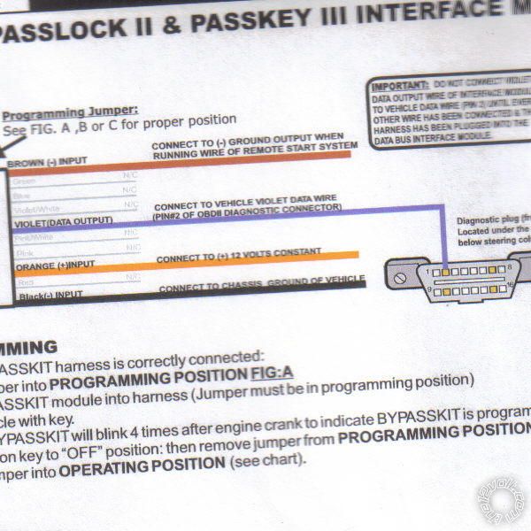 ------------- trying to learn something new everyday!
Replies:
Posted By: i am an idiot
Date Posted: November 21, 2010 at 7:23 PM
On your remote start unit, there is or should be a wire labeled GWR, Ground While Running, or maybe it is labeled Status output. This wire will allow the bypass to only be active when under a remote start situation.
Posted By: macgyver15
Date Posted: November 21, 2010 at 8:31 PM
im looking at diagram but dont see that wire can you take a look at the manual of the viper160xv page 26 or 27 and let me know what you think
-------------
trying to learn something new everyday!
Posted By: kreg357
Date Posted: November 21, 2010 at 8:48 PM
On the Viper 160xv it's called :
BLUE (-) 200 mA STATUS OUTPUT ------------- Soldering is fun!
Posted By: macgyver15
Date Posted: November 21, 2010 at 9:11 PM
thanx for the fast response
-------------
trying to learn something new everyday!
Posted By: macgyver15
Date Posted: November 21, 2010 at 9:20 PM
i'm not seeing that wire only blue/white (-) 200ma 2nd status/defogger its on page 42 of the manual
-------------
trying to learn something new everyday!
Posted By: kreg357
Date Posted: November 21, 2010 at 9:30 PM
That one will work also. Just make sure it is still programmed to (-) 2nd Status Output.
-------------
Soldering is fun!
Posted By: macgyver15
Date Posted: November 22, 2010 at 12:04 AM
another thing i'm having trouble with is this car has a one wire lock and unlock whats would be the easy way to hook this up with a relay or diode?
-------------
trying to learn something new everyday!
Posted By: kreg357
Date Posted: November 22, 2010 at 8:17 AM
The one wire lock system has a few solutions. Your Viper unit outputs a "Flip-Flop" type signal for Lock & Unlock. A simple doide on the Lock output and a diode & 1500 ohm resistor on the unlock output wire might work. IMHO opinion, relays are the best solution. The remote start units I use only output a (-) Lock / Unlock signal and don't have internal relays. I always use the relays method for the one wire systems. Here is a link to the Bulldog wiring : https://www.bulldogsecurity.com/diagrams/extrainfo/diagrams/15941_GRAND-AM_GRAND%20AM%201%20WIRE%20JBS%20UNITS.pdf The top diagram would be OK for you Viper. Additionally, you cold omit the fuse and +12v connection and just connect the White & Yellow wires to ground (Pins 85 and 87 ). Then switch the Lock / Unlock wires between the relays, using the Vipers (+) outputs. ------------- Soldering is fun!
Posted By: macgyver15
Date Posted: November 22, 2010 at 5:44 PM
thanx that was really helpful i'm gonna do it that way
-------------
trying to learn something new everyday!
Posted By: macgyver15
Date Posted: November 22, 2010 at 5:57 PM
can you tell me why most of the things hook to neg(-) side?
-------------
trying to learn something new everyday!
Posted By: macgyver15
Date Posted: November 22, 2010 at 6:03 PM
not trying to be a pain in the ass was just wondering for future reference!
-------------
trying to learn something new everyday!
Posted By: kreg357
Date Posted: November 22, 2010 at 6:08 PM
The (-) signals are usually low current and easier / safer to work with. At the door pins, a ground is easy to create with only one wire.
As for the relay setup wiring change to the Bulldog diagram for the door locks, being as the Viper is already outputting a (+) signal, might as well use that for the relays coil and save the extra wire and fuse. ------------- Soldering is fun!
Posted By: macgyver15
Date Posted: November 22, 2010 at 7:27 PM
so i need 2 relays and the 1500ohm resistor or just one can i get these at radio shack
-------------
trying to learn something new everyday!
Posted By: macgyver15
Date Posted: November 22, 2010 at 7:32 PM
just looked on radio shacks website didnt find it where would i get these from?
-------------
trying to learn something new everyday!
Posted By: kreg357
Date Posted: November 22, 2010 at 7:33 PM
Two 30/40A SPDT relays and one 1500 ohm 1/4 or 1/2 watt resistor. The shack will have the resistor and maybe the relays. The relays can ususally be found at better auto stores. The are many places "online" that list / sell both if you aren't in a hurry. Get the relays with the 5 pin harness.
-------------
Soldering is fun!
Posted By: macgyver15
Date Posted: November 22, 2010 at 8:13 PM
thanks i'll look online for them now thanx for all ur help and might need some more later
-------------
trying to learn something new everyday!
Posted By: macgyver15
Date Posted: November 23, 2010 at 4:35 PM
ogot the relays and resistor wired them the way the diagram said- is there a way to check them before i hook them up to unit? to make sure they work
-------------
trying to learn something new everyday!
Posted By: macgyver15
Date Posted: November 23, 2010 at 5:59 PM
ok so i dont need positive just use both for ground and pos(+) from the unit?
-------------
trying to learn something new everyday!
Posted By: kreg357
Date Posted: November 23, 2010 at 6:55 PM
Ok. In the top diagram, you connected the the white wire to the yellow wire instead of going thru the fuse to +12v.
The relay on the left is the unlock relay with the 1500 ohm resistor on its output. Connect the Vipers GREEN (-) LOCK (+) UNLOCK OUTPUT to the relays' black wire going to pin 86.
The relay on the right is for lock. Connect the Vipers BLUE (+) LOCK (-) UNLOCK OUTPUT to its black wire going to pin 86.
If you wanted to test, put everything together except the Vipers 2 inputs. Connect the relay outputs to the correct lock wire in the car. Briefly touch a jumper wire connected to +12v constant thru a 5a fuse to left relays' pin 86 and the car should unlock. Do the same to the right relays pin 86 and the car should lock. ------------- Soldering is fun!
Posted By: macgyver15
Date Posted: November 23, 2010 at 7:48 PM
ok im gonna try that tomorrow thanx again for ur help but probally gonna need more so be patient with me i know im being a pain in the ass but want to make sure i get it right and ur the guy that seems to be helping me the most thanx
-------------
trying to learn something new everyday!
Posted By: macgyver15
Date Posted: November 26, 2010 at 4:18 PM
ok got the unit today come to find out there is no harness for the lock/unlock GREEN/ blue wires any suggestions got the unit used but works
-------------
trying to learn something new everyday!
Posted By: kreg357
Date Posted: November 26, 2010 at 5:05 PM
There is a Viper/Python Lock Harness listed on ( the big online aution site sometimes called FleaBay ), item number 320610074272. One day four hours left, $3.35 delivered. And another one , Item #200539051251, $3.99 delivered.
-------------
Soldering is fun!
Posted By: macgyver15
Date Posted: November 26, 2010 at 6:43 PM
k i'll try fleabay  ------------- trying to learn something new everyday!
|