viper 5901, 2002 mazda protege 5, 5 spd
Printed From: the12volt.com
Forum Name: Car Security and Convenience
Forum Discription: Car Alarms, Keyless Entries, Remote Starters, Immobilizer Bypasses, Sensors, Door Locks, Window Modules, Heated Mirrors, Heated Seats, etc.
URL: https://www.the12volt.com/installbay/forum_posts.asp?tid=124790
Printed Date: March 23, 2026 at 3:31 PM
Topic: viper 5901, 2002 mazda protege 5, 5 spd
Posted By: chriscollins
Subject: viper 5901, 2002 mazda protege 5, 5 spd
Date Posted: December 03, 2010 at 1:17 PM
I decided to install this unit on my own rather than pay best buy $300 in labor. This is my first alarm/rmote start install and it got pretty overwhelming after seeing all of the wiring. Now from what I've found I don't think I'll need half of it for my install. The more I seem to search, the more I get confused. So I was hoping someone here would be kind enough to help me match the necessary wires from my car to the viper unit and let me know which ones won't be needed at all. Below are the three main harnesses to the viper unit and below that is the vehicle information. From what I can tell this should be just about as simple as they get. Thanks in advance for your help! -Chris
VIPER 5901
➢ Primary harness 12-pin connector
H1/1 RED / WHITE (-) 200mA TRUNK RELEASE OUTPUT
H1/2 RED (+)12v CONSTANT INPUT
H1/3 BROWN (+) SIREN OUTPUT
H1/4 WHITE/ BROWN LIGHT FLASH ISOLATION WIRE - PIN 87a of onboard relay
H1/5 BLACK (-) CHASSIS GROUND
H1/6 VIOLET (+) DOOR TRIGGER INPUT
H1/7 BLUE (-) TRUNK PIN/ INSTANT TRIGGER INPUT
H1/8 GREEN (-) DOOR TRIGGER INPUT
H1/9 BLACK/ WHITE (-) 200mA DOME LIGHT OUTPUT
H/10 WHITE/ BLUE (-) REMOTE START/ TURBO TIMER ACTIVATION INPUT
H/11 WHITE PARKING LIGHT OUTPUT
H/12 ORANGE (-) 500mA GROUND WHEN ARMED OUTPUT
H2 HARNESS, 18pin connector
H2/1__GREEN/ Black_____200mA OEM Alarm Disarm Output
H2/2__ORANGE / Black____200mA Aux 4 Output
H2/3__GREEN / WHITE_____200mA OEM Alarm Arm Output
H2/4__Violet/Black_____200mA Aux 2 Output
H2/5__WHITE/ Black_____200mA Aux 3 Output
H2/6__WHITE/ Violet_____200mA Aux 1 Output
H2/7__Grey/Black______Diesel Wait To Start Input
H2/8__BROWN / Black_____200mA Horn Honk Output
H2/9__Violet/White_____Tachometer Input
H2/10_Dark Blue_______200mA Status Output
H2/11_Pink/White______200mA Flex Relay Control Output
H2/12_Orange_________200mA Accessory Output
H2/13_Purple__________200mA Starter Output
H2/14_Pink____________200mA Ignition 1 Output
H2/15_Grey___________Hood Pin Input H2/16_Blue/White______200mA 2nd Status/Rear Defogger Output
H2/17_Brown__________Brake Shutdown Input
H2/18_Black White_____Neutral Safety Input
➢ Heavy gauge remote start, 10-pin connector
H3/1 PINK (+) IGNITION 1 INPUT/OUTPUT
H3/2 RED / WHITE (+) FUSED (30A) IGNITION 2 / FLEX RELAY INPUT 87
H3/3 ORANGE (+) ACCESSORY OUTPUT
H3/4 VIOLET (+) STARTER OUTPUT (CAR SIDE OF THE STARTER KILL)
H3/5 GREEN (+) STARTER INPUT (KEY SIDE OF THE STARTER KILL WIRE)
H3/6 RED (+) FUSED (30A) IGNITION 1 INPUT
H3/7 PINK/WHITE (+) IGNITION 2 / FLEX RELAY OUTPUT
H3/8 PINK/BLACK (+) FLEX RELAY INPUT 87A key side (if required) of FLEX RELAY
H3/9 RED / BLACK (+) FUSED (30A) ACCESSORY/STARTER INPUT
H3/10 NC (no connection) NC
2002 MAZDA PROTÉGÉ 5 WIRING
PART COLOR LOCATION DIAGRAM
*12 Volt Constant, BLACK/ White (+) and Black (+), Ignition switch harness
*Starter, BLACK/ Blue (+), Ignition Switch Harness
*Starter 2, N/A
*Ignition 1, Blue (+), Ignition switch harness
*Ignition 2, BLACK/ Red (+), Ignition switch harness
*ACCESSORY /HEATER Blower 1, BLACK/ White (+), Ignition switch harness
*ACCESSORY /HEATER Blower 2, N/A
*Keysense, N/A
*Parking Lights (-), Brown (-), Headlight switch
*Parking lights (+), Light GREEN/ Black (+), Drivers Kick Panel
*Power Lock, Light GREEN/ Red (1-wire door lock system) @ module, high in drivers kick panel
*Power Unlock, same wire
*Lock motor wire, Red (+) 2 door lock relays
*Door Trigger, BLACK/ Blue (-), In drivers kick panel
*Domelight supervision, use door trigger
*Trunk Release, N/A
*Sliding Power Door, N/A
*Horn, BLACK/ Red (-), @ steering column harness
*Tach, PURPLE / White, @ diagnostic connector
*Wait to start light, N/A
*Brake, GREEN/ YELLOW (+), @ switch above brake pedal
*Factory alarm disarm, Light Green (-), @ door lock module left of steering column
*Anti-theft, N/A
Replies:
Posted By: zerepdivad
Date Posted: December 03, 2010 at 10:59 PM
why is it that people who have no business installing stuffo n their own come on here and make up to maybe 5 posts asking to be spoonfed how to do something and then they never again post?....
-------------
A DMM is a beautiful thing.
MECP Advanced Installer Certified.
Posted By: chriscollins
Date Posted: December 03, 2010 at 11:41 PM
why is it that someone who know's what they're doing can't take 5 minutes of their time to help someone who's searched for literally hours on there own? I've seen plenty of posts just like this one receive plenty of feedback while searching on my own. Most of my searching led me to this site. Isn't this what this whole site is set up for?
Posted By: zerepdivad
Date Posted: December 03, 2010 at 11:48 PM
just figured i'd see how you reacted. well which ones do you know you need already? i'd rather not go through the whole thing.
here's the ones you'll use for sure
thick red, RED / black,RED / white, thick purple, think pink, pink/white, thick orange,
white parking light wire, 451m relay pack, brown siren wire, thin red to 12v
BLACK/ white stripe to ground, PURPLE / white to tach, gray to hood pin switch that comes with unit,
That's the basic ones i thought of off the top of my head. once you get into it post up specifics.
-------------
A DMM is a beautiful thing.
MECP Advanced Installer Certified.
Posted By: chriscollins
Date Posted: December 04, 2010 at 12:16 AM
451m relay pack? h3/1 and h3/6 both go to the ignition 1? while h3/2 and h3/7 go to my ignition 2 connection? these are thowing me off. can someone please explain all of the flex relay inputs and outputs, are they really necessary?
Posted By: zerepdivad
Date Posted: December 04, 2010 at 12:20 AM
red, RED / white, RED / black go to 12volts. pink to ignition, pink/white ignition 2, orange to accessory, purple to start
Did you 5901 not come with a 451m relay pack?
only time they really don't is if it's a refurb off of ebay or someother unauthorized seller...
-------------
A DMM is a beautiful thing.
MECP Advanced Installer Certified.
Posted By: chriscollins
Date Posted: December 04, 2010 at 12:59 AM
No relay pack. I bought it from CarAudioGiants.com, it was suppose to be new and not reburbished. Any how what's the purpose of the orange accessory wire?
Posted By: zerepdivad
Date Posted: December 04, 2010 at 1:00 AM
turns on accessories..
-------------
A DMM is a beautiful thing.
MECP Advanced Installer Certified.
Posted By: chriscollins
Date Posted: December 04, 2010 at 1:09 AM
Duh.lol and to hook it up in manual mode all i have to do is hook up the blk/w neutral safety wire to the ebrake? does it matter what wattage 1500 ohm resistor i use to wire in the keyless entry with a one wire system?
Posted By: zerepdivad
Date Posted: December 04, 2010 at 1:13 AM
no for manual mode you have to hook up door triggers and tach and trigger a relay to bypass the clutch during crank as well as the neutral safety to the parking brake.
-------------
A DMM is a beautiful thing.
MECP Advanced Installer Certified.
Posted By: chriscollins
Date Posted: December 04, 2010 at 1:16 AM
I think I get the door triggers and tach but how do I bypass the clutch? Do I tap into one of the wires on the neutral safety switch on the back of the pedal?
Posted By: zerepdivad
Date Posted: December 04, 2010 at 1:20 AM
It depends you'll have to use your multimeter to test what exactly happens at the clutch switch when it's pressed. it varies by car.
-------------
A DMM is a beautiful thing.
MECP Advanced Installer Certified.
Posted By: chriscollins
Date Posted: December 04, 2010 at 1:28 AM
ok. so in the first harness i have wires h1/4,6,7,9,10,12 not being used or does the orange ground when armed output need to be used? 11 i need to figure out how to do the lights. In the second harness i think the only wires i need are the tach, brake, and neutral safety input. and the third harness i think i have figured out.
Posted By: chriscollins
Date Posted: December 20, 2010 at 12:49 PM
I finally got around to installing my system yesterday. Everything went rather well except I can't get the remote start to work. I had the reveiver inside the car learn the tach signal. I go through the manual trans shutdown procedure and the car stays running while I remove the key and exit the vehicle. As soon as I arm the system it shuts off. However a few seconds after I arm the system I get a "Remote Start Error", if I try to start the car I receive the same error message and 7light flashes. I don't understand how it can take over during the shutdown procedure but not start on it's own. Is there something else I need to program?
Posted By: chriscollins
Date Posted: December 21, 2010 at 1:48 PM
So after messing with it a little more, I got it to work. It seems that I was arming the system a little to early when exiting the car. By staying in the car while doing the exiting procedures I noticed that my door open light on the dash remained illuminated for a few seconds after I had closed the door. Waiting until the light went off and then arming the system seemed to take care of my issue. For my first install I think it went rather well. And to anyone who may find this in the future, I'll be posting the connections needed for this specific install in another post when I have more time in the next few days.
Posted By: chriscollins
Date Posted: December 23, 2010 at 12:52 PM
Here is a list of all the connections I made, anything not listed wasn't hooked up. So just cut them short to keep them out of your way and make it a little neater install.
H1/2 RED (+)12v CONSTANT INPUT- To the BLACK/ white wire in the corner of the ign harness or the black wire in the ign harness. There are two BLACK/ white wires in the ign harness the other is the accessory.
H1/3 BROWN (+) SIREN OUTPUT- to siren red wire
H1/5 BLACK (-) CHASSIS GROUND- I grounded this with a stock ground right below the fuse box
H1/8 GREEN (-) DOOR TRIGGER INPUT- To BLACK/ blue in drivers kick panel
H1/9 BLACK/ WHITE (-) 200mA DOME LIGHT OUTPUT- Tie into H1/8 or run directly to same BLACK/ blue wire in the drivers kick panel
H1/1 WHITE (-) PARKING LIGHT OUTPUT-To brown wire at headlight switch (don't forget to set the fuse polarity to (-) in the brain)
H2 HARNESS, 18pin connector
H2/8__BROWN / Black_____200mA Horn Honk Output-To BLACK/ red wire at steering column harness
H2/9__Violet/White_____Tachometer Input-To violet/white wire at diag port in engine bay.
H2/10_Dark Blue_______200mA Status Output-To Clutch bypass relay in the diagram below.
H2/15_Grey___________Hood Pin Input-To the hood pin switch
H2/17_Brown__________Brake Shutdown Input-To the GREEN/ YELLOW wire at the brake pedal
H2/18_Black White_____Neutral Safety Input-I wired it to the ebrake wire. Might also be wired into the pink/green wire on the transmission.
Heavy gauge remote start, 10-pin connector
H3/1 PINK (+) IGNITION 1 INPUT/OUTPUT-To ignition 1 Blue (+), at the ignition harness
H3/2 RED / WHITE (+) FUSED (30A) IGNITION 2 / FLEX RELAY INPUT 87-12v constant.Black or BLACK/ white wire at ign harness.
H3/3 ORANGE (+) ACCESSORY OUTPUT-To the BLACK/ white wire in the ign harness.There are TWO. NOT the one in the corner of the connector.
H3/4 VIOLET (+) STARTER OUTPUT (CAR SIDE OF THE STARTER KILL)-Cut the BLACK/ blue wire at the ign harness. This goes to the car side.
H3/5 GREEN (+) STARTER INPUT (KEY SIDE OF THE STARTER KILL WIRE)-To the key side of the cut BLACK/ blue wire at the ign harness.
H3/6 RED (+) FUSED (30A) IGNITION 1 INPUT-12v constant. Black or BLACK/ white wire in the corner of the ign harness connector.
H3/7 PINK/WHITE (+) IGNITION 2 / FLEX RELAY OUTPUT-Ign 2 BLACK/ red at ign harness
H3/8 PINK/BLACK (+) FLEX RELAY INPUT 87A key side (if required) of FLEX RELAY
Door Lock connector
Blue Unlock-To light GREEN/ red at module high in drivers kick panel
Green Lock-To 1500 ohm resistor then tied into blue unlock wire
*Note-I read on two different sites that two relays are needed to hook up the door lock and unlock wires. So I ended up buying them. After speaking with someone who does this for a living he informed me that they wouldn't be needed. Just the resistor. So save yourself a little time and $15 and don't install these. My keyless works just fine without them.
*Note-You will however need a relay to bypass the clutch switch as shown below.
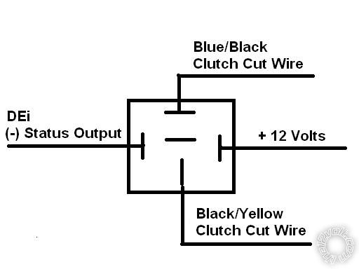
|